Thermal behaviour modelling of superplastic forming tools
Texte intégral
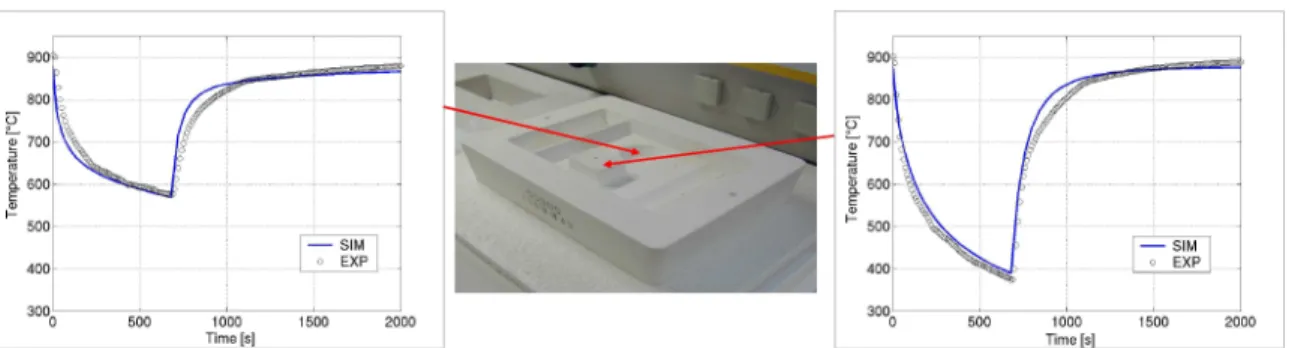
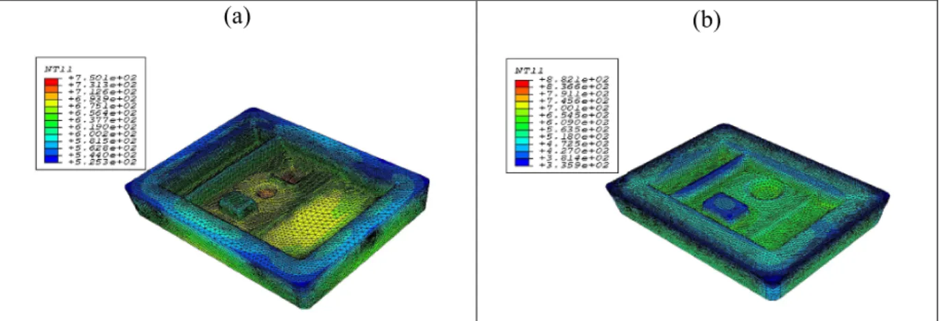
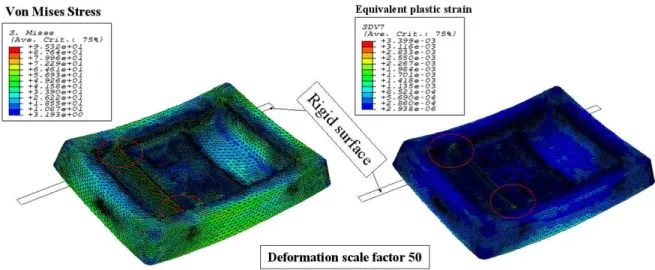
Figure
Documents relatifs
Cependant, le malade ne consent pas par avance à tous les actes ou prescriptions qui lui seront proposés. Il ne s'engage à les suivre que dans une certaine limite en raison du
For the pseudocapacitive system, in situ X-ray (neutron) diffraction or scattering, in situ dilatometry technique, cavity micro-electrode, in situ Raman spectroscopy, TPD-MS
formed (<1%); b) On a gram scale, the Suzuki reaction illustrated in entry 1 of Table 2 proceeds in 79% yield (isolated yield, average of two experiments); c) Under our
Il semble qu'il faille souligner ici que le premier atelier de langage, c'est la table de l'écrivain, et l'on va chercher souvent bien loin ce qu'on peut
The reader comes to share the autobiography as a collectively achieved state of being; the autobiography becomes not a history or a philosophical analysis of a
Si bien el objeto de estudio más original de este crítico, por lo inabordado desde la perspectiva de la negritud, es la literatura de los jóvenes escritores que comienzan a
défense de l'identité professionnelle"; Cette défense est conçue de manière différente, selon que l'on est en présence d'un "corporatisme contractuel", fondé
101 - 54602 Villers lès Nancy Cedex France Unité de recherche INRIA Rennes : IRISA, Campus universitaire de Beaulieu - 35042 Rennes Cedex France Unité de recherche INRIA Rhône-Alpes
