Analysis of the topological charge of vortex beams
using a hole wheel.
Olivier Emile1 , Janine Emile2 , Bruno VIaris de Lesegno3 , Laurence Pruvost3 , and Christian Brousseau4
1 Universit´e de Rennes 1, 35042 Rennes Cedex, France, U.E.
2 IPR, UMR CNRS 6251, Universit´e de Rennes 1, 35042 Rennes Cedex, France, U.E. 3 Laboratoire Aim´e Cotton, UMR 9188, CNRS, Universit´e Paris-Sud, ENS-Cachan, 91405, Orsay, France, U.E.
4 IETR, UMR CNRS 6164, Universit´e de Rennes 1, 35042 Rennes Cedex, France, U.E.
PACS 42.50.Tx – Optical angular momentum and its quantum aspects
PACS 42.25.Fx – Diffraction and scattering
PACS 42.30.Rx – Phase retrieval
PACS 42.79.Sz – Optical communication systems, multiplexers, and demultiplexers
Abstract – The measurement of the topological charge of a vortex beam is demonstrated using the diffraction pattern produced by hole wheel. The resulting mandala-like interference pattern depends on the number of holes relatively to the topological charge. The interference at the cen-tre of the pattern -bright or dark- enables us to determine the topological charge in a procedure when hole wheels with different number of holes are applied. This method is direct and wave-length independent. It does not require any image analysis and could find applications in classical telecommunications or quantum optics using twisted light.
Introduction. – It has been recently demonstrated that the bit rate of free-space communications can be dramatically enhanced without requiring more bandwidth, just by exploiting the spatial phases of twisted beams. This has been evidenced with electromagnetic waves, both in radio [1, 2] and in optics [3–5]. In this context, and also more generally, the exact determination of the Orbital Angular Momentum (OAM) of the beam, also called the topological charge, is a key-point [6, 7]. Consequently, exploring methods to measure the OAM remains a highly challenging issue [8].
It exists many methods to determine the topological charge of twisted beams. A natural one is the direct measurement of the amplitude and the phase of the electric field. In the radio-frequency domain, a x-y scanning detector can do it [1, 9]. Unfortunately, this cannot be done for high frequency waves, like in optics. Wavefront analyzers can be an alternative [10]. Otherwise, some methods are based on mode transformation into an easy identified pattern [11, 12] or into a simple mode, using elements which provide directly the topological charge value [13, 14]. Other solutions exploit the momentum transfer from a twisted beam to a small object, and a measurement of the torque effect [15–17]. All these methods are wavelength dependent. Nevertheless, the most popular techniques use interferences with a plane wave [18–20] or interferences through special shaped apertures [21–26] including the classical Young’s interferences [27, 28]. However, these methods based on interference pattern analysis, are well adapted for low OAM values and become hard for larger values as
Laser
L1
L2
Mask
Interferences
λ= 633 nm
D
VPP
Fig. 1: Experimental set up. VPP: Vortex Phase Plate. The variable thickness of the VPP induces a phase variation. L1 and L2: lenses. The beam is probed by hole wheel.
the pattern becomes highly modulated. In this letter we demonstrate that the diffraction by a hole wheel provides a direct method to determine the topological charge, without pattern analysis, but only by recording the interference state on the propagation axis. We also discuss how the method can be extended to large OAM measurement.
Experimental set up. – The experiment is sketched in Fig. 1. A twisted Laguerre Gaussian (LG) beam is generated from the fundamental beam of a linearly polarized He-Ne laser (λ = 633 nm, Melles Griot, P = 1 mW). We use a vortex phase plate having ` sectors (RPC Photonics) [29] to create them. Their topological charge can be chosen from ` = ±1 to ±8.
The LG beam is diffracted by a p hole wheel, having holes with d = 0.15 mm diameter, regularly spaced on a circle of radius R = 2.5 mm. R is chosen to be of the order of the LG beam radius to get a correct brilliance for detection, but, as described hereafter, the method works in principle for any R values. The mask of hole wheel is realized with an ordinary laser-printed transparency and is fixed on a xy support to centre the wheel on the LG beam centre. The interference pattern is viewed at a D = 5 m distance on a screen and recorded by a CCD camera. The interference pattern (see Fig. 2), visible with the naked eye, exhibits a mandala-like pattern whose centre is bright when p divides ` (if ` 6= 0). Based on this property, with a set of hole wheels and a detector placed at the pattern center, we can determine the topological charge.
Theoretical considerations. – Let us focus on the intensity on the wheel axis. All the interfering paths have the same length (see Fig. 3). If the diffracting points are all in phase, they interfere constructively, leading to a bright spot in the shadow of the mask. Otherwise, they interfere destructively, leading to a dark spot. This is like in a dark spot of Arago interferences for twisted beams [33], but considering only discrete diffracting points instead of a continuous diffracting disk.
To describe the diffraction pattern, let us consider the phase of the incident LG beam with a charge `, at the hole wheel plane. The phase φ is known to be [13]
φ = `θ (1)
where θ is the azimuthal angle in the (r, θ, z) cylindrical coordinates. If we assume the same origin for the azimuthal angle and for the p hole wheel, then the phase of the LG beam at the nthhole equals
l=8
p=8
p=9
p=7
l=0
l=-1
Fig. 2: Mandala-like interference patterns for ` = 8, 0, −1 and p = 8, 9, 7. Bright spot in the centre for ` = 8, p = 8, and ` = 0 whatever p, dark spot otherwise. The arrows are guides for the eye to exemplify the spot. Note that the for p = 8, ` = 8 and ` = 0 are alike, as well as for p = 7 and p = 9 with ` = 8 and ` = −1.
As shown in Fig. 3, the interference pattern results from the propagation of each p partial waves at the output of the holes. Obviously, if p divides `, the waves exiting the p holes have exactly the same phase and the diffracted field is maximum on the axis due to the symmetry of the device (see Fig. 3b), giving a bright spot in the mandala-like pattern. More precisely, because the field on the axis is characterized by the sum
p−1 P n=0
eiφn, then, if p does not divide `, the field equals zero (except for ` = 0). The mandala-like pattern is fully determined by the quantity 2π`/p. Because 2π`/p = 2π + 2π(` − p)/p, then, for a given p value, the patterns for ` and ` − p are the same. It is what we observe in Fig. 2, for p = 9 (second column), ` = 8 and ` = −1 (first and third lines).
The mandala-like pattern can be precisely expressed by the Fresnel diffraction at the distance D, for the hole wheel transmission t(r, θ). On the axis, the diffracted path is
l=8, p=8
D
R
θ
φ
δθ
2π/l
4π/l
6π/l
a)
b)
c)
2π/p
δθ
Fig. 3: a) Phase variation of the beam on the wheel. The white circles correspond to the holes of the wheel. The diffracted light from the holes may or may not be in phase, depending on p. As p = ` (here ` = 8), they are all in phase. b) For a given D, the diffracted paths on the axis are the same. c) The purple zone corresponds to the transmission of the mask vs θ. δθ corresponds to the azimuthal angle variation on one aperture.
√
D2+ r2and the field is
E ∝
Z Z eik√D2+r2 √
D2+ r2A(r)e
i`θt(r, θ)rdrdθ (3)
where A(r) is the radial dependence of the incident LG beam amplitude and k the wave vector. Assuming that the holes are small enough and approximated by radial tiny slits, we have t(r, θ) = T (r)t(θ), leading to separated integrals over r and θ. The field amplitude on the axis is then proportional to
E ∝ Z 2π
0
t(θ)ei`θdθ (4) Eq. 4 is the ` component of the Fourier series of the transmission t(θ). It equals zero when t(θ) does not contain any `-periodicity. Note that the interference state -bright or dark- is only governed by the square of integral in Eq. 4. It does not depend on the sign of ` neither on the distance D.
Results and discussion. – We have performed experiments with ` = 8 using various mask of p hole wheels (p = 7, 8, 9), see Fig. 2. As expected, for p = 8, we observe a bright spot in the middle of the mandala-like interference pattern, whereas for p = 7 and p = 9 there is a dark spot surrounded by a light ring in the middle of the pattern. It is worth noting that the patterns are similar to the ones obtained by scanning tunneling microscopy to probe quasicrystals [34]. Here, however, the diffraction pattern is derived from the symmetry of the distribution of the holes in the wheel (and not from the atomic positions of a material)
and for visible light (and not for X-ray plane waves). Indeed, for X-rays, the symmetry of the diffracted sample is studied for large distances D to explore the interference pattern as a whole. Here, the topological charge of the twisted laser beam can be identified even with short distances D.
We have compared these patterns with the case ` = 0 (plane wave) and ` = 1, analyzed with the same wheels. The mandala (` = 8, p = 8) is similar to the (` = 0, p = 8) one, whereas (` = 8, p = 9) and (` = 8, p = 7) are similar to (` = 1, p = 9) and (` = 1, p = 7) respectively. The patterns are governed by the absolute value of ` − p. The slight discrepancies between the mandalas are probably due to the hole size: the phase variation over the aperture, which is about `d/R, should be small compared to 2π (see Fig. 3c). This leads to
d 2πR
` (5)
which is nothing but the circle perimeter divided by the beam order. Here the criterion is not fully fulfilled for ` ≥ 8. We could have worked with smaller holes. They are not easy to produced with the laser printer resolution, but they could be designed with dedicated drilling machines or lithography.
Nevertheless, we have checked that, for the centre of the pattern only, the interference leads to a bright spot when the topological charge is a multiple of the number of holes in the wheel, otherwise, it leads to a dark spot. Besides, since this spot arises from the diffraction of several points that interfere on the symmetry axis, it is a self reconstructing beam [33]. It is robust against propagation and tiny phase variations, even close to the mask, (D is of the order of few centimeters). The CCD camera could be easily replaced by a simple photodiode placed on the axis. Moreover, there is no need for image or speckle analysis.
One can even propose an apparatus inexpensively determine the topological charge ` of a twisted beam (see Fig. 4). The incident beam is assumed to be a twisted beam. The beam is split by several beam splitters that can be grouped as powers of prime numbers. Each part is sent to a p hole wheel (p = 2 to 100) followed by a photodiode on the beam axis. If ` is a multiple of p, there is a bright spot and a signal on the photodiode, otherwise, there is no signal. For example, we have tested its principle, introducing various hole wheels for a ` = 8 twisted beam. The spot is dark for p = 3, 5, 7, 11, 13. It is bright for p = 4, 8 and dark for p = 16. One can then unambiguously conclude, assuming ` ≤ 100, that ` = 8. This method is fast, direct and most of all, it is wavelength independent.
Our method differs from previous ones that also used pinholes to measure topological charges [21, 30–32]. Those either compared the interference pattern or the light speckle with simulations [21,32], or used algorithms [30,31] to determine `. Indeed, with our method, the topological charge is obtained without treatment algorithm by applying a series of p hole wheel having different values of p. It is just a two alternative determination whether there is light intensity in the center or not. This can be performed with a simple photodiode. Besides, contrarily to other methods D can be freely chosen, giving a versatility to the method.
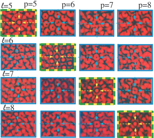
Topological charge recognition. – One can then wonder whether these masks can be used to identify twisted beams. We probe several beams propagating along the same axis with ` = 5 to 8 with four wheels with p = 5 to 8. The interference pattern and the spot in the middle of the pattern are investigated for each beam and each mask (see Fig. 5). The interference patterns that have a bright spot in the middle of the pattern indeed correspond to ` = p. Those having a dark spot in the middle of the pattern correspond to ` 6= p. The number of holes in the wheel determines the absolute value of the topological charge ` of the beam. To get the sign of ` , one can couple this method to double-slit interference technics [27, 28]. Indeed, whereas double-slit experiment provides highly modulated pattern in the case of high ell values, the bending of the pattern gives its sign. Besides, in the case of superimposed copropagating coaxial LG beams, this method could even give access to the
p=7
p=49
7
5
3
2
p=5
p=25
p=3
p=9
p=27
p=16
p=4
p=8
p=2
p=81
p=64
Fig. 4: Schematic drawing of the proposed apparatus for the OAM measurement. The beam is split by several beam splitters and sent to p hole wheel (doted line) with a photodiode on the axis. For a ` = 8, only p = 2, 4 and 8 hole wheels lead to a bright spot. For non-prime-power numbers, if one would have found a bright spot for p = 2, 3, 5 and dark spots otherwise, the topological charge would have been equal to ` = 2 × 3 × 5 = 30.
relative amplitudes after calibration of the detector.
Thus, when dealing with topological charges which are prime numbers between each others, one can readily, unambiguously and simply sort them using the corresponding masks and a detector at the centre of the pattern. If there is a signal then ` corresponds to the number of holes.
Moreover, when one uses several twisted modes multiplexed (superimposed and propa-gating along the same axis) [2, 35], like in a telecommunication system, one can simply sort them with a tiny detector positioned behind the centre of the wheel that has a given number of holes p. The signal detected would be the one corresponding to the twisted mode with a topological charge equal to the number of holes. If one can split the copropagating beam in several parts and uses a different mask after each beam, one could extract the signal carried on each twisted mode. This could be a cheap and elegant way to measure them, without any image analysis after detection.
Conclusion. – To conclude, we have developed an original method to measure the absolute topological charge of a twisted beam using regularly spaced apertures. It is based on the existence of a bright spot in the middle of the mandala-like interference pattern. It can also sort twisted beams and combinations of twisted beams that propagate on the same axis. It can be readily used in telecommunication demultiplexing systems, without any numerical treatment of the image.
Our method is specially well adapted to measure high topological charges. It is not restricted to LG beams and could be directly applied to any twisted beam, as for non diffracting Bessel Gaussian beams. Those are popular among scientists dealing with entan-glement [14, 36–39], especially since high degree of entanentan-glement is usually obtained with
p=5
p=6
p=7
p=8
l=5
l=6
l=7
l=8
Fig. 5: Interference pattern of ` = 5 to 8 twisted beams probe with p hole wheel, p = 5 to 8. Patterns with green and yellow framing have a bright spot at the centre and correspond to ` = p. The others have a dark spot (blue framing). The arrows are guides for the eyes to exemplify the spot. This enables to select a beam with a given topological charge.
high order twisted beams (` = ±300) [40]. Besides, high order twisted beams have also been proposed for fundamental tests in quantum gravity or in remote sensing. It could also be applied to measure high topological of charge electron beams [41] that where recently used to probe chiral and magnetic structures.
∗ ∗ ∗
The authors thank Jean Ren´e Th´ebault for technical assistance. Bruno Viaris de Lesegno and Laurence Pruvost thank the research federation LUMAT, the RTRA ”Triangle de la physique” and the regional ”dim NanoK” for financial supports.
REFERENCES
[1] Tamburini F., Mari E., Sponselli A., Thid´e B., Bianchini A. and Romato F., New J. Phys., 14 (2012) 033001.
[2] Yan Y., Xie G.,Lavery M.P.J., Huang H., Ahmed N., Bao C., Ren Y., Cao Y., Li L., Zhao Z., Molisch A.F., Tur M., Padgett M.J. and Willner A.E., Nat. Commun., 5 (2014) 4876.
[3] Wang J., Yang J.Y., Fazal I.M., Ahmed N., Yan Y., Huang H., Ren Y., Yue Y., Dolinar S., Tur M. and Willner A.E., Nat. Photonics, 6 (2012) 488.
[4] Krenn M., Fickler R., Fink M., Handsteiner J., Malik M., Scheidl T., Ursin R. and Zeilinger A., New J. Phys., 16 (2014) 113028.
[5] Strain M.J., Cai X., Wang J., Zhu J., Phillips D.B., Chen L., Lopez-Garcia M., O’Brien J.L., Thompson M.G., Sorel M. and Yu, S., Nat. Commun., 5 (2014) 4856. [6] Romero J., Giovannini D., Franke Arnold S., Barnett S.M., and Padgett M.J., Phys.
Rev. A, 86 (2012) 012334.
[7] Schulze C., Dudley A., Lamm D.F., Duparr´e M., and Forbes, A., New J. Phys., 15 (2013) 073025.
[8] Qassim H., Miatto F.M., Torres J.P., Karimi E. and Boyd R.W., J. Opt. Soc. Am. B, 31 (2014) A20.
[9] Niemiec R., Brousseau C., Mahdjoubi K., Emile O. and Menard A., IEEE Antennas Wireless Propag. Lett., 13 (2014) 1011.
[10] Leach J., Keen S., Padgett M.J., Saunter C. and Love G.D., Opt. Express, 14 (2006) 11919.
[11] Berkhout G.C.G., Lavery M.P.J, Courtial J., Beijersbergen M.W and Pad-gett M.J., Phys. Rev. Lett., 105 (2010) 153601.
[12] Lavery M.P.J., Robertson D.J., Sponselli A., Courtial J., Steinhoff N.K., Tyler G.A., Wilner A.E., Padgett M.J., New J. Phys., 15 (2013) 013024.
[13] Allen L., Beijersbergen M.W., Spreeuw R.J.C. and Woerdman J.P., Phys. Rev. A, 45 (1992) 8185.
[14] Fickler R., Lapkiewicz R., Huber M, Lavery M.P.J., Padgett M.J., and Zeilinger A., Nat. Commun., 5 (2014) 4502.
[15] Demore C.E.M., Yang Z.Y., Volovick A., Cochran S., MacDonald M.P. and Spald-ing G.C., Phys. Rev. Lett., 108 (2012) 194301.
[16] Silva G.T., Lobo T.P., and Mitri F.G. , EPL, 97 (2012) 54003.
[17] Emile O., Brousseau C., Emile J., Niemiec R., Madhjoubi K. and Thid´e B., Phys. Rev. Lett., 112 (2014) 053902.
[18] Bazhenov V.Yu, Soskin M.S. and Vasnetsov M.V., J. Mod. Opt., 39 (1992) 985. [19] Harris M., Hill C.A., Tapster P.R. and Vaughan J.M., Phys. Rev. A, 49 (1994) 3119. [20] Padgett M., Arlt J., Simpson N. and Allen L. , Am. J. Phys., 64 (1996) 77.
[21] Berkhout G.C.G. and Beijersbergen M.W., Phys. Rev. Lett., 101 (2008) 100801. [22] Guo C.S., Lu L.L. and Wang H.T., Opt. Lett., 34 (2009) 3686.
[23] Hickmann J.M., Fonseca E.J.S., Soares W.C. and Ch´avez-Cerda S., Phys. Rev. Lett., 105 (2010) 053904.
[24] Hickmann J.M., Fonseca E.J.S. and Jesus-Silva A.J., EPL, 96 (2011) 64006. [25] Liu Y. and Pu P., Opt. Commun., 284 (2011) 2424.
[26] Anderson M.E., Bigman H., de Araujo L.E.E. and Chaloupka J.L., J. Opt. Soc. Am. B, 29 (2012) 1968.
[27] Emile O. and Emile J., Appl. Phys. B, 117 (2014) 487.
[28] Emile O., Emile J. and Brousseau C., J. Opt., 16 (2014) 125703.
[29] Beijersbergen M.W., Coerwinkel R.P.C., Kristensen M. and Woerdman J.P., Opt. Comm., 112 (1994) 321.
[30] Berkhout G.C.G. and Beijersbergen M.W., J. Opt. A., 11 (2009) 094021. [31] Guo C.-S. Yue S.-J. and Wei G.-X., Appl. Phys. Lett, 94 (2009) 231104. [32] Berkhout G.C.G. and Beijersbergen M.W., Opt. Express., 13 (2010) 836.
[33] Emile O., Voisin A., Niemiec R., Viaris de Lesegno B., Pruvost L., Ropars R., Emile J. and Brousseau C., EPL, 101 (2013) 54005.
[34] Ledieu J., Gaudray E. and Fourn´ee V., Sci. Technol. Adv. Mater., 15 (2014) 54005. [35] Bozinovic N., Yue Y., Ren Y., Tur M., Kristensen P., Huang H. Willner A.E., and
Ramachandran S., Science, 340 (2013) 1545.
[36] Ren X.F., Guo G.P., Hunag Y.F., Li C.F., and Guo G.C., EPL, 76 (2006) 753
234
[38] Krenn M., Huber M., Fickler R., Lapkiewicz R., Ramelow S. and Zeilinger A., PNAS, 111 (2014) 6243.
[39] McLaren A., Mhlanga T., Padgett M.J., Roux F.S. and Forbes A., Nat. Commun., 5 (2014) 3248.
[40] Fickler R., Lapkiewicz R., Plick W.N., Krenn M., Schaeff C., Ramelow S. and Zeilinger A., Science, 338 (2012) 640.
[41] McMorran B.J., Agrawal A., Anderson I.M., Herzing A.A., Lezec H.J., McClel-land J.J. and Unguris J., Science, 331 (2011) 192.