OATAO is an open access repository that collects the work of Toulouse
researchers and makes it freely available over the web where possible
Any correspondence concerning this service should be sent
to the repository administrator:
[email protected]
This is an author’s version published in:
http://oatao.univ-toulouse.fr/21542
To cite this version:
Ayed, Hamdi and Ermont, Jérôme and Scharbarg, Jean-Luc
and Fraboul, Christian Towards a unified approach for
worst-case analysis of Tilera-like and KalRay-like NoC
architectures. (2016) In: 2016 IEEE World Conference on
Factory Communication Systems (WFCS), 3 May 2016 - 6
May 2016 (Aveiro, Portugal)
Official URL:
https://doi.org/10.1109/WFCS.2016.7496535
Towards a unified approach for worst-case analysis
of Tilera-like and KalRay-like NoC architectures
Hamdi Ayed
∗, J´erˆome Ermont
†, Jean-luc Scharbarg
‡and Christian Fraboul
§Toulouse University - IRIT - ENSEEIHT
Email:
∗[email protected],
†[email protected],
‡[email protected],
§[email protected]
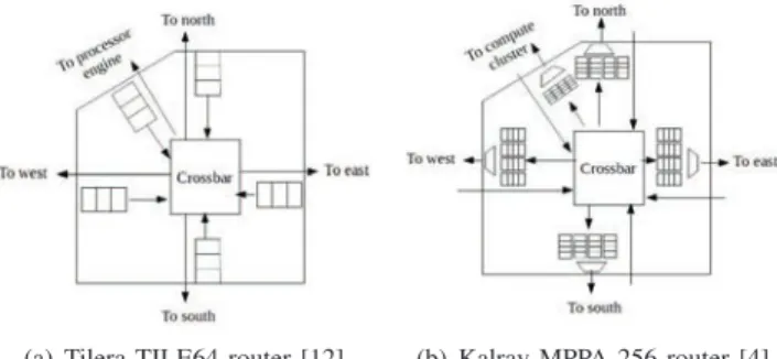
packet. Flit is the transmission unit. In each cycle one flit is forwarded from each router, provided its destination output port (in the next router) is not busy. Figure 1(a) shows the architecture of a Tilera TILE64 router. It includes five full duplex input-output ports. A three flits buffer is associated to each input port. Input ports are polled, based on Round-Robin Arbitration (RRA). The first packet in the buffer of the polled input port is forwarded flit by flit to the next router on its path if the buffer of the corresponding input port is not full. Otherwise the next input port (based on RRA) is polled.
(a) Tilera TILE64 router [12] (b) Kalray MPPA 256 router [4]
Fig. 1. Architectures of two commercial NoC
This strategy requires very small buffers in routers. However a flow can be delayed by indirect blocking, as illustrated in Figure 2. In this example, flowf1can be blocked by flowf2in the upper-left router. The blocking duration can be increased, because f2 can be blocked by f3 later on its path. Thus f1 can be indirectly blocked byf3.
Kalray MPPA 256 eliminates flow control mechanism in routers. Figure 1(b) shows the architecture of a Kalray MPPA 256 router. It includes five full duplex input-output ports. Four sets of buffers are associated to each output port, one for each other input port. For instance the four sets associated with east output port correspond to north, west, south and compute cluster input ports. As soon as a flit arrives in an input port, it is stored in the corresponding buffer of its destination output port. For each output port, buffer sets are polled based on RRA. The first packet in the polled buffer set is transmitted (there is no flow control at this level).
One problem is to ensure that no buffer will overflow. In that way, Kalray MPPA 256 implements flow regulation in source nodes. Each flow bandwidth is limited, leading to a bounded occupancy of each buffer set.
Compared to Tilera TILE64, Kalray MPPA 256 reduces
Abstract—In this paper, we consider two Network-on-Chip (NoC) architectures used within commercially available many-core systems, namely Tilera TILE64 which implements flow regulation within routers and KalRay MPPA 256 which imple-ments flow regulation in source nodes. The Worst-Case Traversal Time (WCTT) on the NoC has to be bounded for real-time applications, and buffers should never overflow. Different worst-case analysis approaches have been proposed for each of these NoC architectures. However, no general worst-case analysis supporting both NoC architectures exists in the literature and most approaches are specific to one of the studied NoC. In this paper, we propose to use Recursive Calculus (RC) method for Tilera and KalRay. Furthermore, we compare the performances on a preliminary case study, in terms of WCTT and required buffer capacity. It allows to quantify the trade-off between delays and buffer occupancy.
I. INTRODUCTION
Many-core architectures are promising candidates to support the design of hard real-time systems. They are based on simple cores interconnected by a Network-on-Chip (NoC). Timing constraints, such as bounded delays, have to be guaranteed for hard real-time systems. Thus worst-case behavior of the NoC is a key feature for such systems.
However, the initial motivation when designing NoCs was to increase the average case throughput. NoCs can thus be used in hard real-time systems either by analyzing the Worst-Case Traversal Time (WCTT) of flows on existing many-cores or by modifying the hardware so that no contentions can occur by design, leading to straightforward WC-TT for flows.
Several NoC have been proposed based on the second approach [7], [8], [11]. However, none of these NoCs target-ing hard real-time constraints are available in commercially existing many-core architectures, such as for instance the STMicroelectronics P2012/STHORM fabric [10], the Tilera Tile CPUs [12] or the KalRay MPPA [4].
In this work, we focus on these commercially existing architectures. More specifically we consider Tilera TILE64 [12] and Kalray MPPA 256 [4], because they consider different strategies for flow control.
Tilera TILE64 implements flow control in each router: a packet cannot be forwarded if the next output port on its path is busy. It corresponds to a classical wormhole switching mechanism [9]. A packet is divided in flow control digits (flits) of fixed size. The first flit is called the header flit. It contains routing information that define the path for all the flits of the
flow delay upper bounds, since the flow regulation eliminates indirect blocking. However required queue size increases with overall flow bandwidth.
The contribution of this paper is to propose a unified approach for delay analysis of both Tilera TILE64 and Kalray MPPA 256, as well as buffer occupancy analysis of Kalray MPPA 256.
Several approaches have been proposed for Worst-Case-Traversal-Time (WCTT) computation of NoC. Two main ex-isting approaches can be used for Tilera TILE64, based on Recursive Calculus (RC) [5] and Network Calculus (NC) [6]. The RC method offers a simple way to capture the wormhole effect and the possible direct and indirect blocking that may be induced in the network. Furthermore, in [6], au- thors have compared these two timing analysis approaches and showed that in practical cases (medium and high loads) the RC methods provides tighter bounds compared to NC method. One approach based on Network Calculus has been pro-posed for delay and buffer analysis of Kalray MPPA 256 [4]. It assumes that the applications use all the available bandwith on the different links. This is not the case for the real-time applications considered in the context of this paper.
In this paper we show how RC can be used for delay and buffer analysis of Kalray MPPA 256. We show how such a unified approach can be used to compare WCTT on both Tilera TILE64 and Kalray MPPA 256. We also show how it can determine the required buffer size for a given application (with known flow bandwidth) on Kalray MPPA 256. A comparison of WCTT and required buffer size is conducted on a preliminary case study.
II. WORST-CASE ANALYSIS FORTILERA-LIKENOC The goal is to compute the WCTT of a flow fi transmitted
on a Tilera-like NoC. fi follows a path which is an ordered
list of links. Different approaches have been proposed in this context. Two of them, based on Network Calculus (NC) and Recursive Calculus (RC) have been compared in [6]. It has been shown that RC based approach provides tighter bounds in practical cases. Several enhancements of this RC based approach have been proposed in order to better consider Flow as well as NoC architecture features. Flow periods are considered in [3] while a pipeline effect is addressed in [1]. Bounds are improved. In the context of this paper we focus on initial RC approach [5], since it is much simpler to extend to Kalray. Taking into account enhanced RC approaches is left as future work.
The Recursive Calculus method [5] defines d(fi, lj) as
the upper bound on the transmission delay of flow fi from
link lj to its destination. It corresponds to the duration from
the moment when the header flit first tries to access link lj
till the complete reception of the packet at the destination. Thus the end-to-end delay for flow fi is upper-bounded by
d (fi, first (fi)), where first (fi)) is the first link of fi
path.
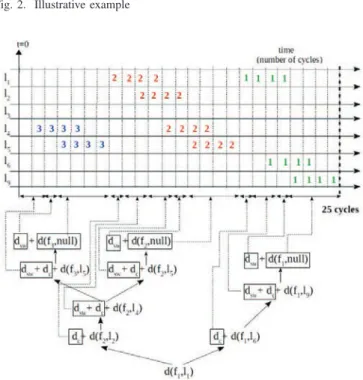
The approach proceeds in a set of recursive iterations which can be represented by a tree. Let’s analyse flowf1of example in Figure 2. This process is illustrated in Figure 3.
Fig. 2. Illustrative example
Fig. 3. W CT T (f1) computation tree of Tilera-like NoC
We have to computed (f1, first (f1)), i.e. d (f1, l1). This is the root of the tree. Firstf1 is delayed at its first linkl1 by
f2 which has to access linkl2. As soon asf1 reaches router
R1, it is transmitted on link l6. Then, f1 reaches router R4 and it is transmitted on linkl9. It cannot be delayed on this last link, since there is no competing flow. Thus we have to add two durations:
• the blocking time off1in its source node, due tof2(left child ofd (f1, l1) node),
• the transmission time off1till its destination, as soon as
l1 is free (right child ofd (f1, l1) node).
The second duration is obtained by adding the time dc
needed to move the first flit off1from its source node to input buffer of routerR1, the timedsw+ dc needed to compute the
route atR1and move the first flit off1fromR1toR4, the time to compute the route at R4 and the time needed to transmit onef1 packet on linkl9, i.e.S1/C. In the Recursive Calculus method, this transmission time is denotedd (f1, null). Without loss of generality, we assumedsw= dc= 1 cycle.
The first duration is the sum of the timedc needed to move
and the time needed to transmit a packet off2to its destination starting from linkl2, i.e. d (f2, l2).
Since f2 is the only flow transmitted on link l2, we have
d (f2, l2) = dsw+dc+d (f2, l4). Indeed, we have to take into
account the time needed to compute the route at R2 and then move one flit fromR1toR2 and the time needed to transmit a packet of f2 from R2 to its destination.
Sincef2shares linkl4withf3, we have to add the blocking time off2inR2due tof3 and the transmission time off2till its destination. These two durations do not include blocking time. Thus they are computed liked(f1, l9), as shown in Figure 3.
Thus, assuming thatSi/C = Si×dc, we getW CT T (f1) =
7 ∗ dsw+ (6 + S1+ S2+ S3) × dc= 25 cycles.
III. WORST-CASE ANALYSIS FORKALRAY-LIKENOC
An approach for worst-case analysis of Kalray has been proposed in [4]. It is based on Network Calculus theory [2]. Available bandwidth is split between flows, insuring that no link is overloaded. Each flow is modeled by its allocated bandwidth, thanks to the classical(σ, ρ) leaky bucket concept, whereσ is the largest burst and ρ is the long term rate of the
flow. Based on Network Calculus theorems, the method derives a WCTT as well as a worst-case buffer occupancy for each flow.
In this paper, we consider that each flow is strictly periodic and the overall application does not use all the available band-width on the different links. Thus a straightforward application of the approach in [4] leads to very pessimistic WCTT.
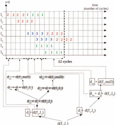
Here we propose to adapt RC based approach in Section II to Kalray. We illustrate this adaptation using the same example (Figure 2). Figure 4 shows the adapted computation tree. It is a copy of Figure 3 where terms which are removed are crossed out.
First, terms corresponding to indirect blocking are removed (single line cross out). Indeed, Kalray does not implement flow control within routers. Thus indirect blocking will never occur. Second, the influence of a directly blocking flow ends as soon it leaves the path of the flow under study. In the example ilustrated in Figure 4,f2does not impactf1after linkl1, since they are stored in different buffers in R1 (south output port forf1, west output port forf2). Thus, in Figure 4, double line cross out terms are removed.
Finally it leads to W CT T (f1) = 2 ∗ dsw+ 3 ∗ dc+ S1∗
dc+ (S2− 1) ∗ dc= 12 cycles.
The maximum occupancy for each output port buffer set can be deduced from RC computation. This computation determines all the packets which can delay the flow under study. The worst-case backlog experienced by this flow in a given output port is determined by considering all the competing packet in the buffer set of this output port. For flow
f1, its only competing packet is from flowf2 and it does not share any router buffer withf1. Thus the maximum occupancy of buffers crossed byf1is one packet from f1.
If we analyse flowf2, it shares compute cluster output port of R3 with one packet fromf3. Thus it leads to a maximum backlog of a packet off2 and a packet off3.
Fig. 4. W CT T (f1) computation tree of KalRay-like NoC
For any buffer set of any output port the maximum buffer occupancy is obtained by analysing all the flows which cross this buffer set and considering the largest computed backlog.
IV. CASE STUDY
We consider the case study in Figure 5, where 6 flows,f1to
f6, are exchanged on a 3*3 2D-mesh NoC. These flows have static paths and are strictly periodic. For all the flows, a packet size of 50 flits and a period of 1000 cycles are considered. The goal is to evaluate the WCTT and the buffering occupancy of the routers for both the Tilera-like and the Kalray-like NoCs using the RC method described in previous sections.
TABLE I
FLOWS CHARACTERISTICS ANDWCTT Flow Kalray RC (cycles) Kalray NC (cycles) Tilera (cycles) f1 258 4204 417 f2 258 4204 417 f3 207 5255 417 f4 103 3153 103 f5 156 5255 156 f6 103 3153 103
Table I summarizes WCTT obtained by RC method for both Tilera and Kalray NoCs as well as WCTT for Kalray NoC considering a straightforward application of the NC method in [4] (σ = 50 flits and ρ = 100050 flits per cycle). We can observe that Kalray NoC experiences lower WCTT than Tilera NoC. The difference corresponds to the removing of the indirect blocking flows and the limitation of direct blocking flows. Such situations do not occur for flows f4,f5 andf6. Table I shows that the straightforward application of the NC method is very pessimistic. This is due to the fact that in this example the links are lightly loaded (never more than 15%).
Table II gives the maximum occupancy of one FIFO queue and all the FIFO queues. For Tilera NoC, one FIFO queue is always 3 flits. This leads to 135 flits for all the FIFO queues (5 queues per router and 9 routers). For Kalray NoC, one FIFO queue size has to be 150 flits in order to guarantee that, based on the application constraints (packet sizes and periods), there will be no overflow. It leads to an overall queue size of 27000 flits (20 queues per routers and 9 routers). These results show that, even on a very simple application, removing flow regulation within routers leads to a very large increasing of the queue size.
TABLE II BUFFER SIZE
NoC architecture queues (flits)One FIFO queues (flits)All FIFO
Tilera-like 3 135
KalRay-like 150 27000
Results of table I and II show that a trade-off between the queue and the delays has to be found.
V. CONCLUSION AND PERSPECTIVES
In this paper we propose an unified approach to analyze different types of NoCs: Tilera NoC which implements flow regulation within routers and Kalray NoC which implements flow regulation in source nodes. This approach is based on Recursive Calculus. We applied this approach on a very basic case study.
This approach has to be formalized and applied to larger case study. Then, the proposed approach is based on the initial RC [5]. It should be improved using results of more recent works [3], [1].
Finally, another question concerns the impact of queue size on WCTT. To what extend can we decrease the flow WCTT by increasing queue size?
REFERENCES
[1] L. Abdallah, M. Jan, J. Ermont, and C. Fraboul. Wormhole networks properties and their use for optimizing worst case delay analysis of many-cores. In Industrial Embedded Systems (SIES), 2015 10th IEEE
International Symposium on, pages 1–10, June 2015.
[2] R. L. Cruz. A calculus for network delay, part i: Network elements in isolation. IEEE Trans. on Information Theory, 37(1):114–131, 1991. [3] D. Dasari, B. Nikoli´c, V. N´elis, and S. M. Petters. NoC Contention
Analysis Using a Branch-and-prune Algorithm. ACM Trans. Embed.
Comput. Syst., 13(3s):113:1–113:26, Mar. 2014.
[4] B. D. de Dinechin, D. van Amstel, M. Poulhi`es, and G. Lager. Time-critical computing on a single-chip massively parallel processor. In
Design, Automation & Test in Europe Conference & Exhibition, DATE 2014, Dresden, March 24-28, 2014, pages 1–6, 2014.
[5] T. Ferrandiz, F. Frances, and C. Fraboul. A method of computation for worst-case delay analysis on SpaceWire networks. In Proc. of the
4th Intl. Symp. on Industrial Embedded Systems (SIES), pages 19–27,
Lausanne, Switzerland, July 2009.
[6] T. Ferrandiz, F. Frances, and C. Fraboul. A Network Calculus Model for SpaceWire Networks. Proceedings of the EEE International Conference on Embedded and Real-Time Computing Systems and Applications (RTCSA 2011), 2011.
[7] K. Goossens, J. Dielissen, and A. Radulescu. Æthereal network on chip: Concepts, architectures, and implementations. IEEE Design & Test of
Computers, 22(5):414–421, 2005.
[8] A. Hansson, M. Subburaman, and K. Goossens. Aelite: A flit-synchronous network on chip with composable and predictable services. In Proc. of the Conf. on Design, Automation and Test in Europe
(DATE’09), pages 250–255, Nice, France, 2009.
[9] L. Ni and P. McKinley. A survey of wormhole routing techniques in direct networks. IEEE Transactions on Computers, 26(2):62–76, Feb 1993.
[10] D. Rahmati, S. Murali, L. Benini, F. Angiolini, G. De Micheli, and H. Sarbazi-Azad. Computing accurate performance bounds for best effort networks-on-chip. IEEE Transactions on Computers, 62(3):452– 467, March 2013.
[11] M. Schoeberl, F. Brandner, J. Sparsø, and E. Kasapaki. A statically scheduled time-division-multiplexed network-on-chip for real-time sys-tems. In Proc. of the Intl. Symp. on Networks-on-Chip (NOCS), pages 152–160, Copenhagen, Denmark, May 2012.
[12] D. Wentzlaff, P. Griffin, H. Hoffmann, L. Bao, B. Edwards, C. Ramey, M. Mattina, C.-C. Miao, J. F. B. III, and A. Agarwal. On-chip interconnection architecture of the tile processor. 2007.
![Table I summarizes WCTT obtained by RC method for both Tilera and Kalray NoCs as well as WCTT for Kalray NoC considering a straightforward application of the NC method in [4] (σ = 50 flits and ρ = 100050 flits per cycle)](https://thumb-eu.123doks.com/thumbv2/123doknet/3170588.90467/5.918.107.416.718.788/summarizes-obtained-tilera-kalray-kalray-considering-straightforward-application.webp)
