To link to this article :
DOI:10.1016/j.jss.2016.09.027
URL :
http://dx.doi.org/10.1016/j.jss.2016.09.027
To cite this version :
Hamid, Brahim and Perez, Jon Supporting
Pattern-Based Dependability Engineering via Model-Driven Development: Approach,
tool-support and empirical validation. (2016) Journal of Systems and
Software, vol. 122. pp. 239-273. ISSN 0164-1212
Open Archive TOULOUSE Archive Ouverte (OATAO)
OATAO is an open access repository that collects the work of Toulouse researchers and
makes it freely available over the web where possible.
This is an author-deposited version published in :
http://oatao.univ-toulouse.fr/
Eprints ID : 17251
Any correspondence concerning this service should be sent to the repository
administrator:
[email protected]
Supporting
pattern-based
dependability
engineering
via
model-driven
development:
Approach,
tool-support
and
empirical
validation
Brahim
Hamid
a ,∗,
Jon
Perez
ba IRIT, University of Toulouse, 118 Route de Narbonne, 31062 Toulouse Cedex 9, France b IKERLAN-IK4 Research Centre, Mondragon, Spain
Keywords: Dependability Safety System engineering Patterns Meta-modeling Model driven engineering
a
b
s
t
r
a
c
t
Safety-criticalsystemsrequireahighlevelofsafetyandintegrity.Therefore,generatingsuchsystems in-volvesspecificsoftwarebuildingprocesses.Manydomainsarenottraditionallyinvolvedinthesetypesof softwareproblemsandmustadapttheircurrentprocessesaccordingly.Typically,suchrequirementsare developedadhocforeachsystem,preventingfurtherreusebeyondthedomain-specificboundaries.This paperproposesasolutionforsoftwaresystemdevelopmentbasedonthereuseofdedicatedsubsystems, i.e.,so-calleddependabilitypatternsthathavebeenpre-engineeredtoadapttoaspecificdomain.Weuse Model-DrivenEngineering (MDE)todescribedependabilitypatternsand amethodologyfordeveloping dependablesoftwaresystemsusingthesepatterns.Moreover,wedescribeanoperationalarchitecturefor developmenttoolstosupportthe approach.Anempiricalevaluationoftheproposed approachis pre-sentedthroughitspracticalapplicationtoacasestudyintherailwaydomain,whichhasstrong depend-abilityrequirements,tosupportapattern-baseddevelopmentapproach.Thiscasestudyisfollowedbya surveytobetterunderstandtheperceptionsofpractitionersregardingourapproach.
1. Introduction
Safety-critical systems require a high level of safety and in-tegrity. Therefore, the generation of such systems involves spe-cific softwarebuildingprocesses.Theseprocesses areoften error-prone becausethey are notfully auto-mated, evenifsome level of automatic code generation or model-driven engineering sup-port is applied. Furthermore,manycritical systemsalso have as-surance requirements, ranging from very strong levels involving certification (e.g., EN-50,129 (CENELEC, 1999 ) for railwaysystems and DO-178B(RTCA, 1992 ) forairborne systems) to reduced lev-els based on industry practices. These systems can be found in manyapplicationsectorssuchasautomotive,aerospace,andhome
control, and come with many common characteristics,
includ-ingreal-timeandtemperatureconstraints,computational process-ing, powerconstraints and/or limitedenergy andcommon extra-functionalpropertiessuchasdependability,securityandefficiency (Ravi et al., 2004; Kopetz, 2011 ).
The integrationofvarious concerns,such asdependability, re-quires the availability of both application development and ex-pertise. Many domains not traditionally involved in this type of softwaredevelopment andmustadapttheir currentprocesses
ac-∗
Corresponding author. Fax: + 33 5 6150 4173.
E-mail addresses: [email protected] (B. Hamid), [email protected] (J. Perez).
cordingly. Typically,such requirements are developed ad hoc for each system,preventingfurtherreusebeyondthedomain-specific boundaries. Thisisespeciallytrueforrailwaysystems,asthey ex-istinmanyusecases.Manyofthesesystemsbelongtocritical in-frastructures, where other economic andsocialaspects are based on.Hence capturingandprovidingthisexpertisevia dependability patterns (Daniels and Vouks, 1997; Powel, 2003; Tichy et al., 2004; Radermacher et al., 2013 )hasbecomerecentlyanareaofresearch. Dependability patternsenable thedevelopment ofdependable ap-plicationsandliberatethedeveloperfromhavingtoaddress tech-nicaldetails.Webelievethatthespecificationandpackagingof de-pendabilitypatterns canprovidean efficientmeans ofaddressing theseproblems,improvingindustrialefficiencyandfostering tech-nology reuse acrossdomains(thereuseofmodelsatdifferent lev-els), thus reducing thetime andeffortrequired todesigna com-plexsystem(McClure, 1997; Agresti, 2011 ).Model-driven engineer-ing (MDE)(Selic, 2003; Atkinson and Ku ¨hne, 2003 )alsoprovides a very usefulcontributionto thedesign ofsafety-criticalsystems (Ziani et al., 2012; Panesar-Walawege et al., 2013 ) because it re-ducesthetime/costrequiredforunderstandingandanalyzing sys-temartifactdescriptionsduetotheabstractionmechanisms. More-over,itreducesthecostofthedevelopmentprocessthankstothe generation mechanisms. Hence, dependability pattern integration mustbeconsideredduringtheMDEprocess.
Insystemandsoftwareengineering,designpatterns(Gamma et al., 1995; Henninger et al., 2007 )areconsideredeffectivetoolsfor the reuse of specific information. Theyare widely used todayto provide architectsanddesignerswithreusable designknowledge. They are triples that describe solutions for commonly occurring problems inspecific contexts. Indeed,pattern-based development hasrecentlygainedmoreattentioninsoftwareengineeringby ad-dressing new challenges that had not been targeted in the past (Henninger et al., 2007 ). Infact,they areappliedinmodern soft-ware architecture for distributed systems, including middleware andreal-timeembeddedsystems(Schmidt and Buschmann, 2003 ). There are patterns forgeneric architecture problems(Buschmann et al., 1996, 2007 ),security(Schumacher, 2003 ;Fernandez, 2013 ), safety (Alexander et al., 2007; Preschern et al., 2013 ) and other non-functionalrequirements(Powel, 2003 ).Therelatedapproaches promote the use of patterns via reusable design artifacts. How-ever, a gap between the development of systems using patterns andtheinformationinthepatternrepresentationsremains(Zdun and Avgeriou, 2008 ).Thisbecomesevenmoreobservablewhen ad-dressingspecificconcerns,suchasdependability.
Inthispaper,wepresent amodel-basedapproachfor depend-abilitysystemandsoftwareengineeringthatuses patterns to rep-resentdependabilitysolutionsandknowledge,whichfostersreuse. Insuchavision,thedependabilitypatternsderivedfrom(resp. as-sociated with) domain-specific models are designedto assist the application developer integrate application models with depend-abilitybuilding-blocksolutions.Dependabilitypatternsaredefined from a platform-independent perspective (i.e., they are indepen-dent of the implementation) and are expressed in a consistent mannerwithdomain-specificdependabilitymodels.Consequently, they will be much easierto understand andvalidate by applica-tion designers in a specific area. This work is conducted within the contextofa model-basedsecurity anddependabilityresearch project,andourcollaborationwithsafety-criticalsystemsuppliers suggested aneed forthiswork.The dependability solutionsused by safety-critical systemdevelopers are based on the application domain and occasionally on the software development environ-ment, includingthe designandcoding stages.There isa needto linktheseconcepts todependability,whichwilleasethe certifica-tionprocess.Thelackofappropriatelinksbetweenapplication do-main conceptsanddependabilityconcepts posesthreemain chal-lenges.First,thedependabilityengineermustre-engineerits exist-ingsolutions.Second,theapplicationdesignermaynotunderstand domain-specific dependabilitysolutions.Finally,it isverydifficult for thesystemdevelopertoguarantee theavailability of depend-abilitysolutionstocoverallthedependabilityrequirementsofthe targetedapplicationusingtheapplicationdomainconcepts.
To provide a concrete example, we introduce a railway case study from the TERESA project1 called Safe4Rail, which is a
simplified version of a real ETCS (European Train Control Sys-tem) (UNISIG, 2009; Stanley, 2011 ). Themainfunctionalityofthis demonstrator is to ensure that the traveled speed and distance
do not exceed the authorized maximum values provided by the
railwayinfrastructure.Toimplementthisfunctionality,thesystem is composed of multiple subsystems, including the European Vi-tal Computer (EVC), which executes thesafety application, anda setofodometrysensorsandactuators.Theodometrysensors pro-videthespeedandaccelerationofthetrain.Withthesevalues,the systemmustbeabletocalculateaccuratespeedandposition val-ues(odometry).Thereisafamilyofproductsintherailwaysector, including regional trains, tramways,and high-speedtrains. These units share common parts,although they differ indistinct ways. Forexample,considerthecalculationoftheactualspeed and
po-1http://www.teresa-project.org/ .
sition by Safe4Rail. The implementation varies accordingto each typeoftrainproduct,whichdependsonthesafetyleveltobemet and the type and number of sensors and actuators that are in-volved. These considerations greatly influence how each product isimplemented because severalissues shouldbe considered:the numberofchannelredundancies,thediversityofthechannels,the monitoringofthechannels,andtheinteractionwithassorteddata (type,weight,etc.).
A proprietary embedded system has been designed to meet
stricter safety regulations. Inour case, the SIL4 level is pursued. Toachievethislevel,severaldesigntechniquesfromrelated stan-dards, such as IEC-61,508 (IEC, 2010b ) and EN-50,126 (CENELEC, 1999 ),areused,includingredundancies,votations,diagnostics,and secureandsafe communications. Hence, capturingand providing thisexpertiseby means ofa repository ofdependability patterns
andmodels canenhance thedevelopment of embeddedsystems.
We seekmechanismsthat allow a safer,easier andfaster safety-criticaldevelopmentprocess.Toillustratethisstatement, two dif-ferent railway industry scenarios are described. The first takes placewithin a railwaymanufacturing group, whereas second oc-curswithinanSME.
Scenario1. Railway manufacturing group. The first scenario takes place within a group of railway manufacturers. The group is di-videdintosubsidiarycompaniesthatspecializeinthedevelopment of train and railwayinfrastructure systems (e.g., traction, central control,infotainment,railwaysignaling, interlocking, Communica-tionBased Train Control(CBTC) (IEEE, 2004 ),etc.). The group in-tendstodevelopitsownsafety-relatedsubsystemsinsteadof buy-ing them from providers and competitors. The problem is that theengineeringcost associated withthesesafety-relatedsystems isrelatively high;moreover, thenumberof qualifiedengineers is limited. Additionally, safetyconcepts anddesign patternsare not presentincommonlyusedmodelinglanguages(e.g.,UML, SysML, etc.), which leads to design ambiguity. The expected benefits for this scenario are the following: (1) reduce product development cost and time by reusing design patterns for other projects and companies,and(2) reduce theprobability ofsystematicfaults by reducingambiguity.
Scenario2. SME company. Inthesecondscenario,anSMEthat de-velops safety-related embedded systems is presented. This com-pany has proven experience in the development of IEC-61,508-basedsafety-relatedembeddedsystems,althoughthecompanyhas littleexperience intherailwaydomain.Ifthiscompany wants to entertherailwaymarket,itmustovercomeagreatbarrierand an-alyze relevant railway standards, adapt the solutions it has been usingforyearsinother sectors,andbereadyforsuccess.Someof theproblemsarethesameasthosethatariseinthefirstscenario: the development cost for safety-related systems is high, and the numberofqualifiedengineersislimited.Additionally, inthis con-text,systemsaredevelopedwithdifferentstandardsderivedfrom IEC-61,508(thedifferencesarewellknown).Theexpectedbenefits forthisscenarioarethefollowing:(1)reduceproductdevelopment costandtime,withthecross-domainreuseofdesignpatterns be-tween projects; (2)reduce the probability of systematic fault by reducingambiguity;and(3)provideacross-domainarsenalof de-signpatternsthatcanbeusedinnewdomains.
Toaddressissuesrelatedtoscenario1,aninfrastructurethat al-lowsthereuseofthemostcommontechniquesusedtoachievethe dependabilityrequirementsinmostsubsystemswouldallowthese subsidiaries to reduce efforts, andcosts while also reducing the numberofrequiredandscarcesafetyexperts.Withregardto the issuesrelatedtoscenario2,weofferaninfrastructurethatallows the cross-domain reutilization of the techniques used to achieve thetargetsafetylevel.
1.1. Solution overview
To address the above problem, we propose an approach that
combines model-driven technology and pattern-based
develop-ment to address thedesign of dependable applications.Our pro-posed approach makes use of patterns as is primary technique: Patten Based System Engineering (PBSE) .PBSEfocuseson patterns; from this perspective, it addresses two types of processes: pat- tern definition and system development with patterns .Metamodeling techniquesareusedtorepresentpatternsatagreater levelof ab-straction.Therefore,patternscanbestoredinarepositoryandcan beloadedfordesiredproperties.Asaresult,patternscanbeused as bricks to build applications through a model-driven engineer-ing approach. The associated framework promotes an infrastruc-tureforthemodelingofdependabilitypatternsandprovides spe-cific transformationenginesthat canadaptandgeneratedifferent representations,wherepatternsareclearlyrelatedtodomain mod-els.Supported by anMDE tool suite, PBSEassists thedependable systemengineeringprocess.The resultingtool-chainsupports the twocategoriesofusers:“reuse” consumersand“reuse” producers. Theformercategorycomprisesdeveloperswhoreuseexisting arti-factsfromtherepository,whereasthelattercomprisesdevelopers ofartifactstobestoredintherepository.SuchanMDE toolsuite utilizesDomain-SpecificModelingLanguages(DSMLs)(Gray et al., 2007; Strembeck and Zdun, 2009 )builtonanintegratedrepository ofmodelingartifactsthatfunctionasagroup,whereapatternisat theheartofdevelopment– itsroleshould bespecifiedinall life-cyclestagesofdevelopment.Weusetheopen-sourceEclipse Mod-eling Framework (EMF) (Steinberg et al., 2009 ) and its extended version,EclipseModelingFrameworkTechnology(EMFT)2 tobuild
the support tools forour approach. The EMF provides an imple-mentation oftheEMOF(Essential MOF),whichis asubset ofthe Meta-ObjectFacility(MOF)(OMG, 2008 )calledEcore3.TheEMF
of-fers asetoftoolstospecifymetamodelsinEcoreandtogenerate otherrepresentations.
1.2. Intended contributions
Inordertoempiricallyassesstheproposedapproachand tool-ing, weprovide evidenceofits benefitsandapplicability through an example of a representative industrial case from the TERESA project,i.e.,theSafe4Railapplication.Thecasestudyindicatesthat our approach is feasible in a real industrial context and that it canprovideusefulguidanceinreusingexistingsolutions.Thiscase study is followed by a survey to better understand the percep-tionsofpractitionersregardingourapproach.Thesurveyindicates that practitioners agreeon thebenefitsofadopting ourapproach inarealindustrialcontext.Thenewapproachpermitsfaster pro-ductionandreducesstaff usingproven solutionsinsteadofhiring expensivedependabilityengineers.Becausethepatternconceptual modelcan be appliedto multipleproblemsthrough asimple ex-tension,theseresultssuggestourworkhaswiderapplicabilityand usefulness.Insummary,theworkpresentedinthispaperhasthe following features:(1)a dependabilitypattern-based approachas anewmethodforsoftwaresystemengineeringbasedonthereuse ofpatterns;(2)thedesignofasetofDSMLstospecifythepatterns thatisindependentoftheend-userdevelopmentapplicationsand executionplatforms;(3)thedevelopmentofa setoftoolsto sup-porttheproposedapproach;(4)theapplicationoftheapproachin thecontext ofrailwaysystems;and(5)a surveyto better under-stand the perceptionsof industry practitioners regarding our ap-proach.
2https://eclipse.org/modeling/emft/ . 3 Ecore is a meta-meta-model.
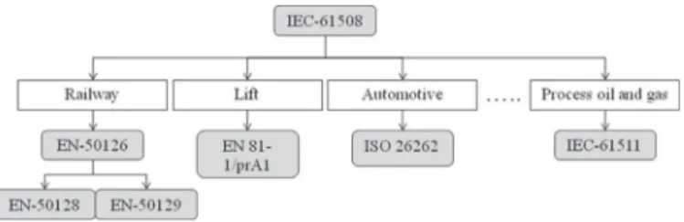
Fig. 1. Domain specific standards derived from IEC 61,508.
The basicformulationoftheapproachpresentedinthisarticle hasbeenpreviously publishedinaresearchpaperatthe16th In-ternationalSystemDesign LanguagesForumonModel-Driven De-pendabilityEngineering(Hamid et al., 2013 ).Thisworkextendsthe ideas described in the earlier paper and presents a holistic ap-proach to the modeling of pattern-based software systems with strongdependabilityrequirements.Specifically,weprovideamore comprehensiveandcompletedescriptionofourapproach(Section 3 )andtoolsupport(Section 4 ),alongwithsubstantialnew empir-ical resultstoshow thefeasibilityandusefulnessofourapproach (Section 5 ).
1.3. Outline
The remainder of the paper is organized as follows. An
overview ofthe modeling framework, includingthe development context, is presented in Section 2 . In section 3 , we present our approach to support the pattern-based system and software de-pendabilityengineering.Section 4 describesthearchitectureofthe tool suiteandpresentsan exampleimplementation.In Section 5 , we present an empirical evaluation of ourapproach through the TERESArailwaycasestudyandasurveyofkeyperformance indi-cators.InSection 6 ,wediscussthecontributionwithregardto cer-tification. Related work is discussed inSection 7 .Finally, Section 8 concludes and sketches future work directions. We investigate a few open issues,primarily the issuesof generalization and im-plementation, including the usability of the proposed modeling framework.
2. Background
Theengineeringofembeddedsystemswithsafetyrequirements typically requires the certification of such products according to generic(e.g.,IEC-61,508(IEC, 2010b ))ordomain-specificstandards (e.g.,EN-5012X (CENELEC, 1999 )).Systemengineersmustdevelop asystemthatcomplieswithrequiredstandards,implementing rec-ommended techniquesand measures. The cost-effective develop-ment and certification of such products is a challenge, and the reusability of provensolutions (design patterns) enablescost and time-to-market reductions.Ourworkaimsatprovidinganew en-gineering approach that allows these solutions (techniques and measures) to be reused for development within the same appli-cationdomainorinacross-domainscenario.
Many domain-specific standards are derived from IEC-61,508, as shown in Fig. 1 . The main characteristic of these standards is that they all share several features (i.e., QM, V&V, life cycle, techniques and measures, etc.) of the main standard, IEC-61,508, whereas other specificpartsaresolelyrelatedtoeach application domainitself.Thesestandardsprovideaspecificsetoftechniques
and measures that must be implemented to achieve the desired
level ofsafetyintegrityofan application(eitherto avoid system-aticfaultsortocontrolrandomfaults).Tofosterreuse,developers must adapt therequirements anddesign solutions ofthese stan-dards totheconceptsoftheapplicationdomain.Asdescribed be-low, a subset of techniques andmeasures proposed in the
stan-Fig. 2. Reference safety engineering process for railway signaling.
dardscanbeusedtodefineseveraldependabilitypatternsusedin thedemonstrator(Section 5 ).
Furthermore, mostofthesetechniques andmeasures are pro-vided in the form ofdesign decisions targeting one stage ofthe developmentlifecyclewithouteffectiverealization.Inaddition,the format inwhichthetechniquesandmeasuresare presentedmust be improved to ensure that the provided solutions are storable, reusable andappropriatefortheautomationofsoftware develop-ment andanalysis. An ontological approachfordescribing design patternsandtheirrelationshipswas proposedin(Girardi and Lin- doso, 2006 )to facilitateunderstandingandreuseduringsoftware development.
Finally, development processes for system and software
con-struction are common knowledge and mainstream practice in
most development organizations. Fig. 2 shows major activi-ties/deliverables associated with a reference railway safety engi-neering process, whereitemsingreen arenewor different com-pared with the IEC-61,508 standard. Every phase receives input documents and defines a set of activities to perform and a set ofoutput documentstogenerate. Theactivities areassignedwith roles and may require specialized tools. The items in green are either not relevant (e.g., validate the system) or not considered within the scope ofourcasestudy(e.g.,hazard log). Inaddition, there is a high level of compatibility between the IEC-61,508-3 andEN-50,128softwaresafetystandards,especiallyregardingtheir software lifecycles andsafetytechniques.The engineeringof em-beddedsystemswithsafetyhasbeenwellestablished(IEC, 2010b ), althoughmethodsandtoolstosupportitarelacking.
Therefore, there are two main prerequisites to define the
pattern-based dependabilityengineeringmethodology. Thefirstis that it must be compatiblewith current development processes. Theobjectiveisnottochangethehabitsoftheengineers;instead, easingtheacceptanceoftheapproachinindustryisthegoal.The second prerequisiteis thatitmustbe flexible enoughtoadaptto otherspecificprocessesinotherdomains.
We seekasolutionbasedonthereuseofsoftwaresubsystems that havebeenpre-engineeredtoadapttoa specificdomain.The
approach described inSection 3 uses MDE techniques to handle theissues described above. Fig. 3 showsthe overall life-cyclefor a safetyrelatedsystem, fromconcept todisposal. Thisfigure has beenextracted fromthe standard IEC-61,508. Comparedto exist-ingmethodologiesfromrelevantstandards,ourworkenhancesthe providedmethodology onlyduring the realization phase ,although itmayhaveapositiveimpact insubsequentphasesoftheoverall productlifecycle,i.e.,fromconcepttodisposal.
3. Approach
A system architect must work at different levels. Integrating all subsystemswhile consideringthe associateddependability re-quirements in a seamless fashion is challenging given the vari-ous critical requirements and uncertainties. We propose a solu-tionforsoftwaresystemdevelopmentbasedonthereuseof dedi-catedsubsystems, so-calleddependabilitypatternsthathavebeen pre-engineered to adapt to a specific domain. The patterns that are attheheart ofour systemengineeringprocess reflect design solutions at the domain-independent and domain-specific levels. WeuseModel-DrivenEngineering(MDE)todescribedependability patterns anda methodology for developingdependable software systems using thesepatterns. The resultant modeling framework reducesthetime/costrelatedtounderstandingandanalyzing sys-temartifactdescriptionduetotheabstractionmechanisms,andit reducesthecostofthedevelopmentprocessduetothegeneration mechanisms.
Theproposedapproach(asillustratedinFig. 4 )iscomposedof sixmain steps (the numbers inparentheses correspond tothose in Fig. 4 ). The first step (step 1) is responsible for the creation of the conceptual model of dependability patterns.The resulting conceptualmodelis usedtobuild a DSMLtospecify dependabil-ity patterns (step 2). The dependability expert with the help of thesystemandsoftwareengineeringexpertusesthisDSMLto de-finedependabilitypatterns(step3).Then,adomainprocessexpert adaptsthedependabilitypatternsintoaversionthatissuitablein itssystemdevelopmentprocess(step4).Anexampleisadaptation
Fig. 3. Overall safety life-cycle (IEC-61,508).
forcompliancewithanappropriatestandard.Wethendevelopand apply appropriatetransformationsofapatternrepresentationina suitable formatforthedevelopment environment(step5).Pattern instantiation astheinitialactivitytoapply apatternisperformed during steps 4and5.Finally,the domainengineer reusesthe re-sultingadaptedandtransformedpatternsforthegivenengineering environment (developmentplatform) todevelop a domain appli-cation (step 6).The patternintegration-applicationinthe designs activityisperformedduringthisstep.
Thefirsttwosteps(1and2)areperformedonceforasetof do-mains. Theinputsofthesesteps areexpertise,standards andbest practices fromthedependabilityexpert.Step3isperformedonce forasetofdomains.Step4isperformedonceperapplication do-main.Performingstep3requiresknowledgeofdependability engi-neering,whereasstep4requiresknowledgeofbothdependability engineeringandthesystemdevelopmentprocessforaspecific ap-plication domain.Step5isperformedonce foreach development environment.Step6isperformedonceforeverysysteminthe ap-plication domain.This steprequires theavailability ofknowledge on the specifictargeted systemanddedicatedtools thatare cus-tomized foragivendevelopmentplatform.Intherestofthis sec-tion, we present detaileddescriptions ofthe sixsteps in our ap-proach.
3.1. Step 1: conceptual model of dependability patterns
Theideaofdesignpatternswasintroducedbyanarchitect (Ur-banist), Christopher Alexander (Alexander et al., 1977 ), not by a software developer. The first objective was to enhance architec-tural quality, beauty, elegance and harmony to avoid dehuman-ization of theliving environment. Design patternshave a certain
number of elements that must be captured by means of a
pat-tern specification language. In GoF (Gamma et al., 1995 ), a de-sign patternextracts the keyartifacts ofacommondesign struc-turethatmakeitusefulforcreatingareusableobject-oriented de-sign.Inourcontext,werefinetheGoFspecificationtofitwiththe non-functional needs. Adapting the security pattern definitionof (Schumacher, 2003 ),wedefinea dependability pattern asa descrip-tion ofa particularrecurringdependabilityproblemthat arisesin specificcontextsandpresentsawell-provengenericschemeforits solution.Therefore,a system of dependability patterns isacollection ofdependabilitypatternsandtherelevantguidelinesfortheir im-plementation, combinationandpractical useindependability en-gineering.
Dependability patterns are defined from a
platform-independent perspective (i.e., they are independent of their
dedicated implementation mechanisms); they are expressed in
a consistent way with domain-specific models. Consequently,
they are much easier to understand and validate by application designers in a specific area. To capture thisvision, we introduce the concept of the domain perspective , where a dependability pattern at the domain-independent level exhibits an abstract solution without specific knowledge of how the solution is im-plemented with regard to the application domain. The objective isto reusethedomain-independentmodeldependabilitypatterns
for several application domains and allow them to customize
those domain-independentpatternswiththeirdomainknowledge and/or requirements to produce their own domain-specific arti-facts. Thus,thequestionofhowtosupporttheseconceptsshould becapturedinthespecificationlanguages.
To foster the reuse of the best practices in software design through patterns, patterns rely on describing the concepts in an abstract way (i.e., domain-independent) and leave it to the soft-ware developerto createan implementation.Incontrast, our de-pendabilitypatternssupportthesoftwaredeveloperinthetaskof exploitingexistingimplementations.Theknowledgeofspecific
im-plementationsusingapplicationdomain constructsiscaptured in domain-specific patterns and thus supports the refinement step. Patternrefinementtakesadvantageofthefactthatapplicationsin thesamedomain,suchasrailwaysystems,havecommon require-ments/standardsandperformcomparabledependabilityfunctions. Themodelingframeworkpresentedinthispaperprovides sup-portforthreelevelsofabstraction:(i)apatternspecification meta-model (SEPM),(ii) a domain-independent pattern model (DIPM), and(iii)a domain-specificpatternmodel (DSPM).This decompo-sition allows design applications within the context of depend-ability by avoiding the extensivecomplexity that is normally in-troducedwhencombiningdependabilityanddomain-specific arti-facts.Moreover,thisapproachassistswithovercomingthelackof formalizationrelatedtotheclassicaltextualpatternform.
Definition1. (Domain). A domain is a field or a scope of knowledge or activity that is characterized by the concerns, methods, and mecha- nisms employed in the development of a system. The actual clustering into domains depends on the given group /community implementing the target methodology.
Inourcontext,a domainmayincludeknowledge ofprotocols, processes,methods, techniques, practices, OS,HW systems, mea-surementandcertificationrelatedto thespecific domain.For ex-ample, inthe group of safetystandards, IEC-61,508 is a domain-independentstandard, whereas EN-50,126, EN81and ISO-26,262 arearailwaydomain-specificstandard,an elevatordomain stan-dardandanautomotivedomainstandard,respectively.
Tospecifydependabilitypatterns,webuildonametamodelfor representing these patterns in the form ofa sub-system provid-ing appropriate interfaces and targeting dependability properties to enforce the dependability system requirements. The so-called external interfaces are used to make the pattern’s functionality availabletotheapplication,whereasthetechnicalinterfaces sup-port interactions with dependability primitives and protocols of theapplication domain,including HW platforms.We capturethe dependabilitycapabilities ofthe patternthrough a novelconcept calledDproperty.
Withregardtotheartifactsusedinthesystemunder develop-ment,the first-classcitizens of thedomain areidentified to spe-cializetheseartifacts.Forexample,thespecificationofapatternin thedomain-independent perspective is basedon softwaredesign constructs.The specification of such apattern fora domainuses adomainprotocoltoimplementthepatternsolution(seethe ex-ampleofasafetycommunicationpatterngiveninSections 3.3 and
3.4 ). Forthispurpose,weintroduce twoconcepts:DIPatternand DSPattern.
These concepts and their related observations are used as a basis for our conceptual patternmodeling language (see Section 3.1.2 ).Thefollowingsubsectiondescribesanexampletoemphasize theissuesidentifiedinthispaper.Then,thefirstlevelof abstrac-tion,namely,themetamodel,isdescribed.
3.1.1. Motivating example: safety communication pattern
As an example of a commonly and widely used pattern, we
choose the safety communication pattern (IEC, 2010a ). In the fol-lowing, the termssafety communicationpatternand black chan-nelpatternareusedinterchangeably.Distributedsafetysystems re-quire(safe)data communicationbetweendistributedsafety func-tions.Forexample,thepresenceofrandomfailuresinthetransfer ofdatawithindifferentlevelsofanapplication,suchas transmis-sionerrors,repetitions,anddeletions, can leadto aloss of infor-mationortoimproperdelivery ofinformation.Ina safety-related systemorapplication,datacommunicationisa vitalpartoftheir development. Thiscommunicationcould occur atdifferentlevels, i.e., on chips, inter-boards, or systems. A safety communication
patternisrequiredforsafety-relatedsystems,wherethedata com-municationisdirectlyinvolvedintheimplementationofitssafety function.
The main purpose of the safety communication pattern is to provideasimplewaytoguaranteethatthecommunicationat dif-ferent levels ina systemis reliableandto provide thecapability to guaranteethe correct transmissionofinformation to theright destinationandattherighttime throughastandard communica-tion mechanism.The functionalityofthispatternisbased onthe detectionofarandomsoftware/hardwarefailureduring communi-cation. Safetystandards let the designer use a standard commu-nicationmechanismtosharetheinformationinasafetyfunction, although the reliability of theinformation is guaranteed through internalsafetyinterfaces,whichhasthefollowingconnotations:
• The elements that share the information must be
safety-relevant.
• TheplatformmustsupporttheimplementationofanError De-tectionCode(EDC).
This strategy leaves the responsibility of this task (at the in-terfaces of the elements participating in the communication) to detect failures during communication at different levels, such as chips, inter-boards, and systems. The safety communication pat-ternprovidesspecific interfacestoguaranteethereliabilityofthe informationtransferandtheauthenticityoftheparticipantsinthe communication. Morespecifically,theparticipantsinthe commu-nication could be independent hardware channels, internal mod-ules,etc.
Let sender and receiver betwoelements actingas communica-tionparticipants.Let sender it f (resp. receiver it f )bea sender in-terface(resp. receiver interface).
The sender it f offersthefollowingservices:
• Generatean identifierforestablishing thesequence ofthe in-formationtobesent.
• Generateanidentifierforthesourceandreceiverofthe infor-mation.
• GenerateanEDC;todetectfailuresintheinformationtransfer. • Packtheinformationbeforesendingitoverthestandard com-munication mechanism. The receiver it f offers the following services:
• Unpacktheinformation.
• Checktopackagebeforetousethereceivedinformationto ex-aminethefollowingaspects:
– theoriginoftheinformation(source), – thedestinationoftheinformation(receiver), – theorderoftheinformationreceivedand – thattheinformationhasnotbeencorrupted. • Sendthereceivedinformationtothereceiver.
Itisimportanttoensurethattheactionsofsendingand receiv-ingthesafetymessagearecyclicalandperiodicalbecauseelements involvedinthecommunicationmustalwaysknowwhenthe mes-sage shouldbe sent andwhenit shouldbe received. Itis impor-tanttosynchronizebothpartsofthecommunicationprocess.How toprotectelementsthatsharetheinformationandhowtoprovide theerrordetectioncoderemaincriticalproblems.
However, thesesafetycommunicationpatternsare slightly dif-ferentwithregard totheapplicationdomain.Forexample,a sys-temdomainhasitsownmechanismsandmeanstoservethe im-plementation ofthispattern, primarilythe technique usedto en-ablereliabledeliveryofdataoverunreliablecommunication chan-nels.Dependingonthetypeoffailurestobedetectedandthe di-agnosticcoveragetobeachieved,theEDCcanbeimplemented us-ing asetofprotocols,suchasrepetitioncodes,paritybits,
check-sums, Cycle Redundancy Checks (CRCs) and hash functions. To
summarize,theyaresimilarintheirgoalanddifferentintheir im-plementationissues,e.g.,determiningthe levelofcommunication inwhichthepatternisusedandtherestrictivenessandefficiency of the expected solution. Thus, the motivation is to handle the modelingofpatternsbythefollowingabstraction.Inwhatfollows, we propose usingCRCs (Peterson and Brown, 1961 ) to specialize theimplementationofthesafetycommunicationpattern. This so-lutionisalreadyusedatthehardwareandoperatingsystemlevels todetectfailures.
3.1.2. Pattern specification metamodel (SEPM)
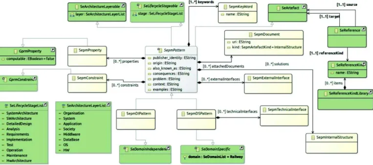
To foster the reuse ofpatterns in the development of critical systemswithdependabilityrequirements,weextendametamodel from (Hamid et al., 2016 ) forrepresenting dependabilitypatterns in the form of a subsystem that provides appropriate interfaces andtargetingdependability propertiestoenforcethe dependabil-itysystemrequirements.Interfacesare usedtoexhibita pattern’s functionalityandtomanageitsapplication. Inaddition,interfaces support interactions betweendependability primitives and proto-cols within aspecific applicationdomain.Theprincipalclassesof the systemand software engineering pattern metamodel(SEPM) are described with Ecore notations inFig. 5 . Their meanings are explainedinmoredetailinthefollowingparagraphs.
• SepmPattern.This block represents a dependabilitypattern as a subsystemthat describesa solution fora recurring depend-ability design problem arising in a specific design context. A SepmPatterndefinesits behaviorintermsofprovided and re-quiredinterfaces.Larger piecesofa system’sfunctionalitymay beassembledbyreusingpatternsascomponentsofan encom-passing pattern or an assembly of patterns; the required and providedinterfacesare wiredtogether.ASepmPatternmaybe manifestedbyoneormoreartifacts.
• SepmDIPattern.ThisisaSepmPatternthat denotesanabstract representationofadependabilitypatternatthedomain- inde-pendentlevel.This isthekey entryartifact tomodelpatterns atthedomain-independentlevel(DIPM).
• SepmInterface. A SepmPattern interacts with its environment viaSepmInterfaces,whicharecomposedofoperations.A Sepm-Pattern represented the provided and required interfaces. A providedinterface highlightstheservicesexposed tothe envi-ronment.Arequiredinterfacecorrespondstoservicesrequired bythepatterntofunctionproperly.We considertwointerface types:
- SepmExternalInterface. This allows the implementation of interactionstointegrateapatternintoanapplicationmodel or to compose patterns. It represents the application ele-menttobeusedduringthepatternintegration-application inthedesigns.Inother words,suchapatternelementwill be replacedwithone elementfromtheapplicationdesign, orcreatedifitexistsinthepatternbutnotinthe applica-tion(aswillbedetailedinSection 3.6 ).Moreover,itwillbe usedtoreasonaboutthepatternpropertiesanditsprovided designsolution.
- SepmTechnicalinterface. This allows the implementation of interactions with dependability primitives and protocols, such as errordetection, andspecialization for specific un-derlyingsoftwareand/orhardwareplatformsduringthe de-ploymentactivity.It representstheplatformelement tobe used during the pattern integration-application in the de-signs. In other words, such a pattern element will be re-placed with one element from the application domain, or createdifitexistsinthepatternbutnot intheapplication. PleasenotethatanSepmDIPatterndoesnothave SepmTech-nicalInterfaces.
Fig. 5. An overview of the SEPM.
Forourexample,onemayidentifythefollowingexternal inter-faces:
– send(S,d, t). Theapplicationsender S sendsdata d attime t . – receive(R,d,t).Theapplicationreceiver R receivesdata d attime
t .
– send(P,d,crc,n,t). The patternsender participant P sends data d attime t withcertainCRC crc andasequencenumber n – receive(Q,d,crc,n,t). The pattern receiver participant Q receives
data d attime t witha certain CRC crc and asequence num-ber n .
• SeReference. This link is used to specify the relationship be-tweenpatternswithregardtothedomainandsoftware lifecy-clestageintheformofapatternlanguage.Forexample,a pat-tern ata certain softwarelifecycle stage uses another pattern atthe sameorat adifferent softwarelifecyclestage. SeRefer-enceKindcontainsexamplesoftheselinks.
• seArtifact.Wedefine amodelingartifact asa formalizedpiece ofknowledgeforunderstandingandcommunicatingideas pro-ducedand/orconsumedduringcertainactivities ofsystem en-gineeringprocesses.Themodelingartifact maybe classifiedin accordancewithengineeringprocesslevels.
• SeLifecycleStage.ASeLifecycleStageSeLifecycleStagedefinesthe developmentlifecyclestageinwhichtheartifactisused.Inour study,we focus on dependabilitypatternmodels. Inthis con-text,weusethepatternclassificationofRiehleandBuschmann (Riehle and Züllighoven, 1996; Buschmann et al., 1996, 2007 ). • SepmProperty.Thisisaparticularcharacteristicofapattern
re-latedtotheconcernofinterestandisdedicatedtocapturingits intent.Eachpropertyofapatternisvalidatedatthetimeofthe pattern validatingprocess, andthe assumptions are compiled asasetofconstraintsthatmustbesatisfiedbythedomain ap-plication.Additionally, thisconceptwill serveforpattern clas-sification andidentification. The dependabilityattributes from (Avizienis et al., 2004 ) are categoriesofdependability proper-ties. For our example, we define the following dependability properties:
- integrity of data. Whendata d arereceivedbytheapplication receiver R ,thosesamedata d aresentoutbytheapplication sender S .
- data freshness. It is oftendesiredthat thetransmitted data d arerecent.Thispropertystatesthat whenan application receiver R receives data d , the same data are sent by the applicationsender S atmostDeltatago.
- non duplication. Givendatathat aresentby theapplication sender S, areceiver R receives thesedataatmostthesame numberoftimestheyweresent.
• SepmConstraint. This is a set of requisites of the pattern. If the constraints arenot met,the patternis not ableto deliver its properties. Forour example,we specifyconstraints on the CRC computation/checking algorithms,on thecorrect/incorrect
transmission over the network and on the maximal network
delay.
• SepmInternalStructure. This constitutesthe implementation of the solution proposed by thepattern. Thus, the InternalStruc-ture can be considered as a white box that exposes the de-tails oftheSepmDIPatternandtheSepmDSPattern. Tocapture allthekeyelementsofthesolution,theSepmInternalStructure manifeststwotypesofstructures:staticanddynamic.One pat-terncanhaveseveralpossibleimplementations,providing sup-portforpatternvariability.
• SepmDSPattern. ThisisarefinementofSepmDIPattern(aswill be detailedinSection 3.4 ).It isusedtobuild apatternatthe domain-specific level (DSPM). Furthermore, a SepmDSPattern has Technical Interfaces tointeractwiththeplatform.Thisisthe keyentryartifacttomodelthepatternattheDSPM.
3.2. Step 2: creation of a DSML from a conceptual model of dependability patterns
To create model instances of the proposed metamodels, we
mustprovideconcretesyntaxes. The DSML’sconcretesyntax may be described inanysyntax type (textual, tree-structured,tabular, diagrammatic, etc.), depending onthe corresponding artifact. For ourpurpose,weproposeusingthewell-knownapproachinMDE: aDSMLthatcontainspattern-specificinformationforseveral soft-ware and systemmodeling languages anddifferent development environments.Thisapproachisusefulbecausewearestoring a li-braryofdesignpatternsinacommonrepositoryandareproviding oneormoreadaptationsofeachpatterntotarget several
applica-tiondomains,e.g.,therailwayindustry,anddifferentdevelopment environmentdomains,e.g.,UML.However,ourvisionisnotlimited toDSML.Forexample,in(Radermacher et al., 2013 ),wedefineda UMLprofileundertheUMLpapyrustool4tospecifypatterns.
In our context, we use a mixed syntax that combines
structured-tree syntax and a UML-based diagrammatic syntax to describe the SEPM’s concrete syntax. The basic idea is that the former definesproblems, objectives andconstraints, whereas the diagrammaticpartdefinesrolesandsolutions (SepmInternalStruc-ture). The objective behind this separation isthat a solution de-finedinthepatterncanbeintegrated(withoutlosinginformation) into the applicationarchitecture only ifboth are specifiedin the samemodelinglanguage,e.g.,UML.Conversely,theproblem state-mentandobjectivesareindependentofthechosenmodeling lan-guage.Theseparationenablessolutionsdefinedindifferent model-inglanguagestosharethesameproblemdefinition,whichis use-fulbecausewearestoringdesignpatternsinacommonrepository wheremodelspecificationsinthestructured-treesyntaxare sepa-ratelymanagedandstored.Apatternmighteventuallyhave multi-plesolutionsdefinedindifferentmodelinglanguages.Thepattern discovery,i.e.,themechanismstobrowseorsearchpatternswithin therepository,arebasedonthenon-diagrammaticpart.
3.3. Step 3: definition of dependability patterns
OncewehavedevelopedtheDSML’sconcretesyntaxinStep2, we can create the setof dependability patternsto share the de-pendability expertise within the domain of interest. During this step, thepatterns are constructed such that they conform to the metamodel description adopted in Step 1. To foster technology reuseacrossdomains,thepatternsarestoredinarepository,such astheonedescribed in(Hamid, 2014 ),thusreducing theamount ofeffortandtimeneededtodesignacomplexsystem.
Furthermore,inthecontextofourwork,weusevalidation re-ports and documentation generation techniques to validate each pattern. If a pattern is correctly defined, i.e., it conforms to its modelinglanguage,thentheartifactisreadyforpublicationinthe repository.Otherwise,we can identifyanyissuesfromthe report and rebuild the patternby correcting orcompleting the relevant constructs.Additionally, each patternisstudied toidentifyits re-lationships withother patternsbelongingtothesameapplication domain based on the engineeringprocess activity in which it is utilized.Thepurposeofthisactivityistoorganizepatternsintoa setofpatternsystems.Moreover,thisstepshouldincludeall activ-itiesthatsupportpatternproducersinmanagingtherelationships amongthesepatterns,whichcanbedefinedinpatternrelationship modellibraries.Ateachstage(phase) n ofthesystemengineering developmentprocess,thepatternsidentifiedintheprevious stage (phase) n −1 can assist in the selection process during the cur-rent phase. As a prerequisite, we specify model libraries for the classification ofpatterns.Ateach stageofthesystemengineering development process,theappropriate patternsareidentified viaa classificationprocess.Otherworkhasadoptedasimilar conceptu-alizationofapattern-baseddevelopmentapproachinthescopeof safetyengineering(e.g.,(Hauge, 2014 )),orinthescopeofsecurity engineering(e.g.,(Uzunov et al., 2013 )).
Afteraninitialanalysisofthevariousartifactsources,including standards and existing applications, the designer determines the stage oftheengineeringprocesslifecycle(systemconcept,system architecture,softwarearchitecture,anddetailedmoduledesign)in whicheachpatterncanbedefined;moreover,whetherthepattern isdomain-independentordomain-specificcanbedetermined.For thispurpose,we choosetousethepatternclassificationofRiehle
4http://eclipse.org/papyrus/ .
andBuschmann (Riehle and Züllighoven, 1996; Buschmann et al., 1996, 2007 ),whodefined system patterns, architectural patterns, de- sign patterns and implementation patterns to create the SeLifecy- cleStage modellibrary. Inaddition, a patternmay be linked with otherpatternsandassociatedwithpropertymodelsusinga prede-fined setofreferencetypes,onaveryhighlevel(Noble, 1998 ) or includingdetailsonwhatpartofapatternisused,refined,or com-bined(Hauge, 2014 ).Here,wecreatethe SeReferenceKind model li-brary to support thespecification of relationships across artifacts (e.g., refines, specializes and uses ) asan extension ofthe relation-shipclassificationproposedin(Noble, 1998 ).
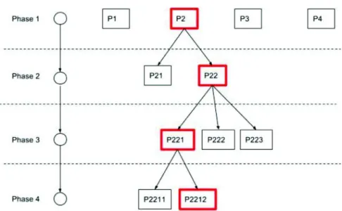
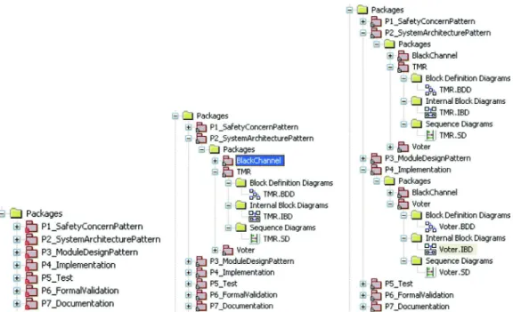
Inthecontextofourwork,certainpatternshaveameaningful representationatthesystemlevel,atwhichgeneralsystemblocks are definedand domain concepts are expressed (e.g., system re-dundancy). However, their representations might not be directly refined in later phases because they represent concepts that are meaningful at onlythe architectural level.In contrast,other pat-terns mightbemeaningfulonlyinlater designphasesasindirect specializations of an architecturalconcept, e.g., a dataagreement software patternisa specializationofan architecturalsystem re-dundancypattern.Inaddition,thesamepatternmayhavemultiple instantiations andspecializations ineach phase (e.g.,a watchdog driver is linked to a hardware component). Therefore, as shown in Fig. 6 ,a givendesignpattern(P2) in therepository might fol-lowatree-shapedrefinementandspecializationflow,representing differentlifecyclephases,differentrefinementsandspecializations, andnewpatternrepresentations inlater phases.The followingis anexampleofspecializationthroughtheprocess:
1. P2 (atSystemConceptSpecificationphase):BlackChannel 2. P22 (at System Architecture Design phase): Ethernet-Based,
Star-TopologyBlackChannel
3. P221 (at Software Architecture Definition phase):
Ethernet-Based, Star-Topology Black Channel with CRC and sequence
numbermonitoring
4. P2212 (atModuleDetailedDesignphase):Ethernet-Based,
Star-TopologyBlackChannelwithCRC andsequencenumber
moni-toring
ThetargetrepresentationistheDIPMlevel,whilestill conform-ing to the SEPM metamodel.At the DIPM level, this description revealsthefollowingelements: interfaces oftype SepmExternalIn-terface, dependability properties oftypeSepmPropertyand solutions oftypeSepmInternalStructure.Moreover,forclassification (respec-tively relationship) purposes, additional information may be de-fined, e.g., lifecycle stages oftypeSeLifecycleStage (respectively re- lationships oftypeSeReference).
The first taskis tocreatea basic patternsubsystemas an in-stance of the SepmPattern. The instance is given a name and a set ofattributes that correspond to the pattern. The description, withvaryinglevelsofabstraction,ismanagedbyinheritance.Once the basic patternsubsystem is specified, interfaces are added to expose someofthepatternsfunctionalities.Foreach interface,an instanceof SepmExternaInterface isaddedtothepatternsinterface collection. The next step after creating interfaces is the creation ofpropertyinstances.Aninstanceiscreatedinthepatterns prop-erty collectionto specify every identified dependability property. A property isgivena nameandan expression based onexternal interfacesinapropertylanguage.
We continue our illustration using the example of the safety communication pattern .Forthesakeofsimplicity,we specifyonly those elements relatedto both steps 2and3that are requiredto explain ourapproach.AsintroducedinSection 3.1.1 ,data commu-nicationmustbesafe,whichleadstotwopossibleapproaches(IEC, 2010a ):
1. White channel: Use of a safety communication channel that is designed, implemented andvalidated accordingto the
IEC-Fig. 6. Tree-shaped pattern refinement and specialization.
Fig. 7. Safety communication pattern structure.
61,508 standard (IEC, 2010b ) andtheIEC-61,784-3 (IEC, 2003 ) or IEC-62,280 (IEC, 2002 ) standards using a certified safety communicationchannel,suchasTTEthernet(TTE)5.
2. Black channel: Useofacommunicationchannelthat isnot de-signedorvalidatedaccordingtotheIEC-61,508standard,where safetymeasurescanbeimplementedeitherinthesafety func-tions or in interfaceswith the communicationlayer in accor-dancewiththeIEC-61,784-3orIEC-62,280standards.Thelatter iscalleda safety communication layer (SCL) .
AsshowninFig. 7 ,thesafetycommunicationpatternisan ap-plication levelserviceon topof anon-safety-related communica-tion stack (“comms”) that enables “safe” data exchange between safetyfunctions.Itmustbedefinedaccordingtoalifecycle equiv-alentto thehighestsafetylevel(SIL)intheapplication, requiring thedetectionofallpossiblecommunicationerrors,suchas corrup-tion, incorrect messageorder, message outside temporal require-ments,messagelost,messageduplicated,etc.
In our example, an instance of SepmPattern is created and
called SCL .Fig. 8 showstheSCL patternforthesoftware architec-ture. An encapsulation unit is used to prepare the datamessage to besent anda de-encapsulationunit toextractthe information fromthemessageonceithasarrived.Thereceiverprovidesan in-terface where some extra informationis added in thesent
mes-5http://www.tttech.com/products/ttethernet/ .
sage,which willbe checkedby the receiver.This information in-cludes(1) asafetycodefor thereceiverto verifytheintegrity of themessageand(2)asequencenumbertoensurethecorrect ar-rivalorder.Thesenderisalsoresponsible formaintaininga mini-mumtransmissionratethatisspecifiedbytherequirementsofthe application. Moreover,the receiverprovides an interface tocheck thereceived message.Thisinterface includes(1) asafetycode to ensuretheintegrityofthemessage,(2)asequencenumber,which guaranteesthatthereceivedmessageisnewandnotareplica trav-elingintothecommunicationchannel,and(3)atransmission qual-itycheckertoreactifitfallsbelowapredefinedlevel.
3.4. Step 4: adaptation for a specific domain
AttheDSPMlevel,thedependabilitypatternandsomeofits re-latedelementsarealsocreatedbyinheritance.Oncea SepmDSPat-tern is created,every patternexternal interface is identified and modeled asa refinement of the DIPM’s SepmExternalInterface in thepattern’sinterfacescollection.Then,followingthepattern’s de-scriptionoftheparticularsolutionthatisrepresented,eachofthe pattern’stechnical interfacesis identifiedand modeled by an in-stanceofSepmTechnicalInterfaceinthepattern’sinterfaces collec-tion.
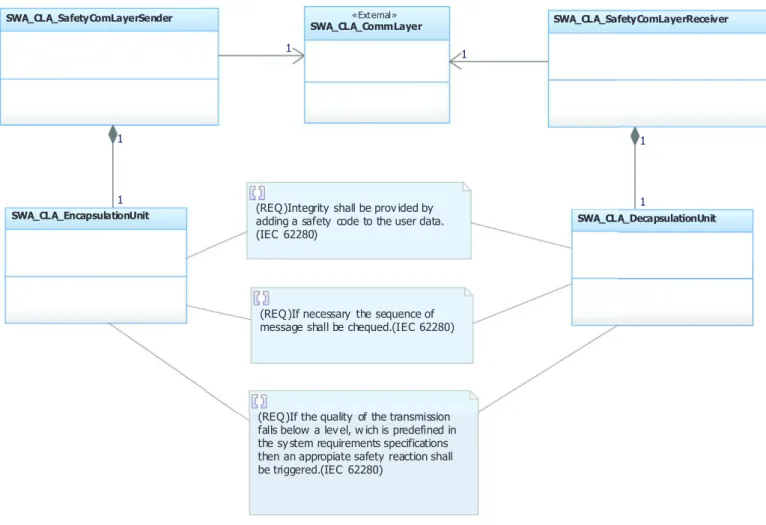
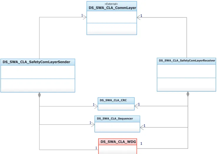
Inthe context of ourexperiment, the railwaydomain-specific patternmustbecompliantnot onlywiththegeneric safety stan-dardsbutalsowithrailway-specificsafetystandards.Fig. 9 shows the SCL pattern for the software architecture. The encapsulation andde-encapsulation unitsdescribed in the domain-independent perspectivearerefinedintosequencer,CRCcalculatorandsoftware watchdogunits.This combinationofelements enablesthe detec-tion oferrors. Asequence numberis added tothe data message todetectan incorrectorderofmessagesand/ormessagesthatare lost.ACRC codeis addedtothe datamessagetodetect message corruption. Eachmessagehas an associatedperiod,anda watch-dogis usedto detectwhetherthemessagearrival time iswithin the specified time range. Thus, the sender provides an interface in whichextra information is added to the sent message, which will be checked by the receiver. This information includes (1) a safetycode(CRC)todetectmessagecorruptionand(2)asequence numberto detect an incorrect order or lost messages.Moreover, the receiverprovides an interface to check the received message throughaCRCchecker.Todetectmessagecorruption,thereceiver
computes a CRC and compares it with the one provided by the
Fig. 8. Black channel for software architecture.
a sequencenumber checkeror usinga qualitychecker through a softwarewatchdog.
3.5. Step 5: adaptation for a specific domain development environment
Thefinalstep(step6)isperformedtosupportthedevelopment of aspecific system inthe applicationdomain.As a prerequisite, step5identifiesappropriatepatternsandcreatestailoredversions that representmodelconcepts inthedomain ofinterestandthat can be adaptedto both thesystemdevelopment process andthe development environment.The selection ofapatternis primarily thechoice ofthedeveloper.Thereare variousconsiderations that may narrow andsimplify thischoice. The first is the purposeof thepatternapplication.Althoughthispurposecannotbegenerally formalized,certainpatternsaddressrequirementsthataredefined bydomainstandards(e.g.,safety).Iftheserequirementsarestored inamodellibraryandarereferencedinthedefinitionsofthe pat-terns,thentheselectionofpatternscouldbe drivenbythe selec-tion of (domain) requirements. The second consideration is that patterns can be classifiedwithrespect toseveral properties.One ofwhichisthestageoftheengineeringprocesslifecyclediscussed inSection 3.3 – apatternmayberelevanttothesystem,its archi-tecture,ortoaspectsofitsdesignorimplementation.Thus,itmust bepossibletofilteravailablemodelingartifactsbasedonthis clas-sification.
Inourcontext,themappingsfromdependabilitypattern mod-els, which are formalized in a SEPM description language, for
a specific domain development environment are supported via
model transformations.Oncetherepository isavailable6,patterns
can be imported/exported from the repository as XMI standard files that are compatiblewithprocesses: Identification and Tailor- ing .
Definition 2. (Identification).Identificationactivitiessupport sys-tem engineersinselectingappropriate solutions fromthe reposi-tory.Thisactivitymakesitpossibletosearchforandretrieve pat-terns inaccordancewiththesystemrequirements.The identifica-tionactivityconsistsofthefollowingtasks:
1.Defineneeds.
2. Searchforpatternsintherepository.
3. Select the appropriate patterns from those proposed by the repository.
Definition 3. (Tailoring).Atailoringactivityinvolvestheretrieval ofapatternanditsrelatedmodellibrariesfromtherepositoryand their incorporationintothetargetdevelopment environment.This activity enablesthereuseof apattern. Thetailoringactivity con-sistsofthefollowingtasks:
1.Adapt theselected patternsforthedomain-specific processof interest.
2. Import the tailored patterns by transforming them into the domain-specificdevelopmentenvironment.
Inthecontextofourwork,thetargetdomaindevelopment en-vironmentisIBMRational Rhapsody7,andthedescriptions ofthe
6 The repository system populated with modeling artifacts. 7http://www-03.ibm.com/software/products/en/ratirhapfami .
Fig. 9. Railway black channel software architecture.
modeltransformationsarebasedontheQVToperationallanguage. Therefore,thedesignofagivenpatterncanberegardedasasingle package that containsone sub-package per lifecyclephase ofthe engineeringprocess;eachofthesephasescancontaindesign mod-ules and additional sub-packages associated with particular spe-cializationsandrefinements.Thus,importedpatternsarestored in-sideadedicatedpackagethatfacilitatessearchingwithinthe pack-agetreeofeachdesign.Moreover,tofosterreuse,thepattern arti-factsrelatedtothat phaseare instantiatedfromthe repositoryto the vehicular modeling tool asa reference package. As shownin
Fig. 10 ,eachpatterndesignpackagegenerallycontainsthe follow-ingitems:
• Any information that is required by the end-user pattern in-tegrator,e.g., aUMLclassorSysML block,withinterfacesthat enabletheinterconnectionofpatternswithagivensystem de-sign.
• Additional detailed information of interest, e.g., a “structure” packagethatcontainsthestaticinternalstructure(e.g.,class di-agram)andthedynamicstructure(e.g.,sequencediagram). 3.6. Step 6: reuse for a specific system development
Thissectionfocusesontheuseofpatternsinasoftware devel-opmentprocess.Theintegrationofapatterninvolvesthe applica-tion ofa solutionprovidedbythat patterninan existing applica-tionarchitecturetotakeadvantageofitsbenefits.Wecannot sim-plycopysuchasolutionintothearchitectureunderdevelopment. Instead,wemustaccountfortheinterplaybetweenelementsthat already exist inthe application andthe elements of the pattern.
The challenge of this taskis that the relationships (e.g., connec-tions, associations or inheritances) defined between elements in thepatterndefinitionmust alsobe establishedin theapplication model.Currently, integrating a patternrequires addingnew con-nections,associations,andotherfactors,andtheusermustresolve potentialconflicts.
Toaddressthisissue,aspecificactivitycalled Integration ,which wasalreadystudiedin(Hamid et al., 2012 ),isusedherein. Definition 4. (Integration). An integration activity is performed within the development environment whena patternand its re-latedmodellibrariesareintroduced intoanapplicationdesign;it allows the elements of the application to be organized for con-sistencywiththeelements ofthepattern. Theintegrationactivity consistsofthefollowingtasks:
1.Preparation. The elements of the patternare extracted in the formofarolediagramtomatch/mergethemwiththeelements oftheexistingapplicationmodel.
2.Elicitation.Connectionsbetweentheapplicationmodelandthe patternbasedon therolediagram areconstructed.Thisphase isresponsiblefordefiningtheelementsoftheapplicationthat areusedtofulfilltherolesidentifiedinthepattern.
3.Consolidation.The patternismergedwiththeapplication. For certain elements ofthe pattern, they may simplybe replaced withelementsfromtheapplicationornewlycreatedelements maybeaddedastheyexistinthepattern.
4.Adaptation. An optional phase that offers the opportunity for tailoredintegrationbyallowingtheusertorefinethenew ap-plicationisconducted.
Fig. 10. Pattern design deployed in packages using the IBM Rational Rhapsody tool.
Inthecontextofourexample,byexecutingatailoringactivity, thepatternisexported inanXMIfile. Then,itmustbe imported from Rhapsody. This two-step approach is an intermediate solu-tionforthepurposeofdemonstration.Theenvisionedfuture solu-tion istoinstalla plug-ininthe designtool sothat patternscan be importedwithoutexternalsoftware.AsshowninFig. 10 ,once thepatternisimportedinRhapsodyasapackage,aprojecttreeis generatedanditsartifactsareavailableintheproject.Therefore,in each phase, the systemdeveloperexecutes thesearch/select task on the repository to tailor appropriate patterns forthe modeling environment using the identification and the tailoring processes described inSection 3.5 .The developerthen integratestheminto the applicationmodels following an incremental process. For ex-ample,theprocessflowatthesoftwarearchitecture phasecanbe summarizedbythefollowingsteps:
1. Thesoftwarearchitectsearchesfordifferentspecializations(at the software architecture-definition level) of the patterns to complementthedesign.
2. Thesoftware architectselectsthe appropriateset ofidentified patterns.
3. Thesoftwarearchitectimportsthesoftwarearchitecturedesign perspective of each patterninto the vehicular modeling envi-ronment(Rhapsody)asareferencepackage.Theapplication de-veloperisresponsibleforlinkingthepatterninterfacesto inte-gratethepatternatthatspecificlevel.
4. The softwarearchitect integrates thepatterninto the existing softwarearchitecturedesigndiagrams.
4. Toolsupport
In this section, we propose an MDE tool chain to support
the proposed approach andassist the developers of model- and pattern-based dependable software systems. As discussed below, theproposedtoolchainisdesignedtosupporttheproposed meta-models; hence,thetool chainandtheremainder ofthe activities involvedinthe approachmaybedevelopedinparallel. Appropri-atetoolsforsupportingourapproachmustfulfillthefollowingkey requirements:
• EnablethecreationoftheUMLclassdiagramsusedtodescribe patternmetamodelinourapproach.
• Enablethecreationofaconcretesyntax.
• Support the implementation of a repository to store pattern modelsandtherelatedmodellibrariesforclassificationand re-lationships.
• Enable the creation of pattern models and the relatedmodel librariesandpublicationoftheresultsintotherepository. • Supporttheadministrationandtheinternalmanagementofthe
repository.
• Enablethecreationofvisualizations oftherepository to facili-tateitsaccess.
• Enablethecreationofapplicationmodels.
• Enable transformationsofthe modelsfromthe repository for-matintothetargetmodelingenvironment.
• Enabletheintegrationofapplicationmodelsandimported pat-terns.
• Supportapplication-specificcodegeneration.
To satisfy the above requirements, we define four integrated setsofsoftwaretools:
• Toolset A forpopulatingtherepository,
• Toolset B forretrievalandadaptationfromtherepository, • Toolset C to serve astherepository software,includingits
ad-ministrationandinternalmanagement,and
• Toolset D astheaugmentedtargetdevelopmentenvironment. There are several environments that can be used to build an MDE tool chain. In this work, the open-source Eclipse Model-ing Framework(EMF) andits extended version, Eclipse Modeling FrameworkTechnology(EMFT) areusedtobuildthesupporttools forourapproach.AllmetamodelsarespecifiedusingtheEMF.The design tools are semi-automatically generated from these meta-models. Several enhancementsare added to the generated code, such as creationwizards, toguide themodeling artifact designer inpopulatingtherepository.Visualenhancementsareaddedto fa-cilitatetherecognitionofdifferentconcepts asafirststeptoward a futurevisual syntax.Todescribe themodeltransformations,the QVT operational language (OMG, 2008 ) isused. Therepository is implementedusingtheEclipse CDO8 framework.However,our
Fig. 11. Pattern designer schematic.
sionisnotlimitedtotheEMFplatform.Othermodelingtools con-formingtotherequirementsofSection 4 canalsobeused.For ex-ample, in(Radermacher et al., 2013 ), we investigated the use of UMLpapyrusanditssupportforthedefinitionofUMLprofilesto providetoolsupportfortheapproach.
Our approach is successfullyapplied to a casestudy ofPBSE. Specifically, we develop Semcomdt9 (SEMCO model development
tools) as an MDE tool chain to support all the steps in our ap-proach.Semcomdtoffersthefollowingfeatures:
• Gaya for specifying and implementing a repository to store models,
• Arabion forspecifyingpatternsthatconformto SEPM ,and • Retrieval forrepositoryaccess.
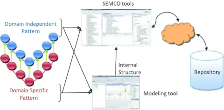
For populating the repository, we construct a pattern design tool (Arabion) tobeused bya patterndesigner. Arabioninteracts with the Gaya repository for publication purposes. As described below,andalreadydescribedinSection 3.2 fromaDSML construc-tionperspective,designpatternsarecomposedoftwoparts,as vi-sualizedinFig. 11:
• Structured-tree component. Pattern definition that defines pat-tern properties and attributes, such as safety properties, re-source constraints, development phases, and relationships. Thesedataareusedtoeasepatternsearchandanalysis(Hamid, 2015 ).
• UML-based diagrammatic component. Pattern internal structure designfilesgeneratedviaadditionaltools,e.g.,Rhapsodyor Pa-pyrus (UML editors), that are stored asXMI files and can be attachedtothepatterndescriptionfile.
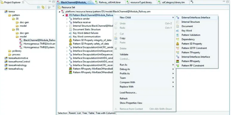
The patterndesign environment ispresented inFig. 12 .There is adesignpaletteon theright,a treeviewoftheprojectonthe left andthemaindesignenvironmentinthemiddle.Furthermore, Arabion includesmechanisms forverifying the conformity ofthe pattern withtheSEPM metamodelandforpublishing theresults totherepository.
Foraccesstotherepositoryby asystemengineer,theretrieval tool provides a set of functions to assist in the search, selection andsortingofpatterns.Forexample,asshowninFig. 13 ,thetool assistsinselectingappropriatepatternsthroughkeywordsearches andlifecyclestagesearches.Theresultsaredisplayedinthesearch resulttreeassystem,architecture,designandimplementation pat-terns.Thetool includesfeaturesforexportandtailoringusing di-alogsthatareprimarilybasedonmodeltransformationtechniques toadaptpatternmodelstothetargetdevelopmentenvironment.
With regard to Tool set D, IBM’s Rational Rhapsody
Devel-oper/Software Architecture10 is used to provide tool support for
theotherpartsofourapproach.Othermodelingtoolscanbeused
9http://www.semcomdt.org .
10http://www.ibm.com/developerworks/rational/products/rhapsody/ .
in accordancewith the target applicationdomain and/or model-ingenvironment.Inadditiontomeetingitsexpectedrequirements, Rhapsody is a mature and well-established tool in the industry, makingiteasiertoprovidesupport forourapproach andmaking ourapproach morelikely tobe adopted bypractitioners, such as those engaged in railwaysafety-related processes. Rhapsody also allowsforapplication-specificcodestobeautomaticallygenerated (exceptforsomespecificpartsthatarecodedbyhand).
Rhapsodyis used asthe domain-specific design software tool todesign(andimplement)thesystemusingUML/SysMLmodeling languages. Forexample, it can be used to design systems based on packages, where one package might contain design diagrams and/oradditionalpackages.Basedonthisapproach,thedesignofa givenpatterncanbeconsideredasinglepackagethatcontainsone sub-package per safety engineering process lifecycle phase; each ofthesephasesmightcontaindesignmodulesandadditional sub-packagesassociatedwithspecializationsandrefinements.Thus,the accesstoolprovidestheoptiontoexportpatternsinaformatthat can be imported by the Rhapsody tools.Therefore, a customized accesstool,suchastheoneshowninFig. 14 ,isdevelopedto con-structconnections betweentherailwaydevelopmentenvironment andthe repository ofpatterns. The access tool offers a GUIthat allowstheuserto searchforandselectpatterns.When apattern isselected,theaccesstoolinstantiatesthepatterninthe domain-specifictool.Becausethistaskisperformedduringproduct devel-opment,theselectedpatternmustbecompliantwiththecurrent phaseofthedomainprocessandwiththeusertools.Byaccessing therepository,we introducefeaturesbasedonmodel transforma-tiontechniquestoadaptthepatternmodeltothetarget develop-ment environment.In our work, the target format is a subset of UMLthatcanbeimportedusingRhapsodyandthemodel transfor-mationsasdevelopedusingtheEclipseimplementationofQVTO.
The left-hand side of Fig. 14 shows the main window of the railway access user interface. This window has two panels: one forsearchingandthe other fordisplay.The display panel on the bottom showsthe nameof theselected pattern andits different views,e.g.,agraphicviewwithaclassdiagramofthepattern im-plementation. Searchingthe repository is performedusing either the“Name” field toenterpartof thenameor“Keywords” to en-terthedesiredpatterncharacteristics.Toimporttheselected pat-tern into the development environment, as shown on the right-handsideofFig. 14 ,theaccesstoolcreatesanewrepresentationof theselectedpatternasa UMLpackageforRhapsodyusingmodel transformationtechniques.
Toassistintheintegrationstep,weprovidesupportforthe var-iousphases.However, certain developmentenvironments may al-readyoffernativeintegrationsupport. AsshowninSection 3.6 ,a bindingmust beestablished betweenelementsof theapplication architecture andtheroles definedinthe pattern. The integration toolsupportsthedeveloperintwodifferentways.Thefirstisthat itenables a filteredselection of possibleelements for binding to be displayed.The second isthat it providesthe completely auto-matedcreation ofbindings. Ifarole remains unboundduring in-tegration,thedevelopercan indicatethatithasnocorresponding element in the application and that a suitable element must be createdintheapplicationmodel.Forexample,in(Radermacher et al., 2013 ), we used UMLcollaborations (OMG, 2011a ) for model-ing patterns andfor role binding to establish linksbetween ele-ments of the application architecture andthe roles definedin a pattern.Furthermore,everydesign patternhascertain constraints thatmustbesatisfiedwhileallowingforacertaindegreeof mod-ification.Thus,thereisaneedtoensurethatthepropertiesofthe patternremainvalidwhilenotpreventingacceptablemodifications (suchas renaming). Averification ruleassociated with each pat-ternensuresthattheinvariantsofthepatterncanbecheckedafter thepatternhasbeenapplied.Thesevalidationrules arecurrently
Fig. 12. Designing a pattern.
Fig. 13. Access tool.
implementedintheprogramminglanguage ofthetarget develop-mentenvironment(e.g.,C++,Java,etc.);alternatively,aconstraint language, such asObjectConstraintLanguage (OCL)(OMG, 2010 ), couldbeused.However,therealizationofsuchrulesisbeyondthe scopeofthispaper.
5. Evaluation
Inthissection,we firstreportonan industrialcasestudy per-formedintherailwaydomain(Section 5.1 ),followedbya descrip-tionofasurveyperformedamongrailwaydomainexpertsto bet-terunderstandtheirperceptionsofourapproach(Section 5.2 ).The case study enables us to determine that the pattern-based ap-proach leads to a reduced number or to a simplification of the engineering process steps, whereas the survey assists in assess-ing whetherdomainexpertsagreeonthebenefitofadoptingthe pattern-basedapproachinarealindustrialcontext.
5.1. Case study
InthecontextoftheTERESAproject,weevaluateourapproach intheconstructionofanengineeringdisciplinethatisadaptedto resourceconstrainedsystemsbycombiningtheMDEprocessanda model-basedrepositoryofdependabilitypatternsandtheirrelated propertymodels.
Inthissubsection,theadaptationofrailwayprocessesto incor-porate thepattern-based approachisdescribed. Wetestwhichof the provided tools are ableto support the patternintegration or assist theengineeringprocess.Inthiscontext,theextendibilityof the patternrepositorywithnewpatternsandtheextendibilityof existing patternsareobserved.Furthermore,weevaluatethe use-fulnessofthepatternswithrespecttoincreasingengineering pro-ductivity. Inthepresentationofthecasestudyanditsresults,we describe onlyasmallportionofthissystem.Wedonotshowthe completeresultingmodelbecauseitcontainsproprietary informa-tionfromourindustrialpartner.
5.1.1. Nature of the case study
One ofthe casestudies that serves asaTERESAdemonstrator issetintherailwaydomain.Forconfidentialityreasons,wedonot reveal thename of thecollaborating partner. This is a very con-servative domaininwhichdependabilityisa keyrequirementfor mostsubsystems.Thus,therailwaydomainisahighlyappropriate sectorinwhichtoapplyourapproach.Itisnotuncommontofind
Fig. 14. Railway access tool.
Fig. 15. ERTMS/ETCS diagram.
situations inthisindustrial domaininwhich thereuseof system and software modeling artifacts by means of a repository could accelerate and supportthe development ofsafety-related subsys-tems. We demonstrate the applicability of our proposed frame-work using the Safe4Rail demonstrator, which isa simplified ver-sion ofa realETCS(EuropeanTrainControlSystem)forsignaling, control and train protection (see Fig. 15 ). Additionally, for confi-dentiality reasons, we use a small but realistic setting to illus-trate the dependability pattern-based approach proposed herein. The main functionalityofthisdemonstratoris toensure thatthe speed and distance traveled do not exceed the authorized max-imum values specified by the railway infrastructure. Safe4Rail is responsible for emergency braking in a railway system. Its task
is to detect whetherthe brakeshould be activated.Most impor-tantly, the emergency brake must be activated when something goeswrong.
Atevery position,the brakingcurveprovides threespeed lim-its,whichare usedtomakedecisions aboutwhento activatethe brakes(seeFig. 16 ):
1.When thecurrentspeed exceedsthe warningspeedlimit, the systemmustactivateawarningsignaltoadvisethedriverthat thetrainisapproachingadangerousspeed.
2.If the driver does not take any action and the service speed limitisexceeded,thesystemmustactivatetheservicebrake.