HAL Id: hal-00706382
https://hal.archives-ouvertes.fr/hal-00706382
Submitted on 16 Jun 2012
An Approach for Evolution-Driven Method Engineering
Jolita Ralyte, Colette Rolland, Mohamed Ben Ayed
To cite this version:
Jolita Ralyte, Colette Rolland, Mohamed Ben Ayed. An Approach for Evolution-Driven Method
En-gineering. John Krogstie, Terry A. Halpin, Keng Siau. Information Modeling Methods and
Method-ologies, Idea Group, pp.80 - 101, 2005. �hal-00706382�
An Approach for Evolution-Driven Method
Engineering
Jolita Ralyté
*, Colette Rolland
**, Mohamed Ben Ayed
** * Université de Genève, CUI, Rue de Général Dufour, 24CH-1211 Genève 4, Switzerland [email protected]
** Université Paris 1 Sorbonne, CRI, 90, rue de Tolbiac
75634 Paris cedex 13, France
[email protected]; [email protected]
Abstract. This work considers the evolutionary perspective of method engineering. It presents an approach for method engineering based on the evolution of an existing method, model or meta-model into a new one satisfying a different engineering objective. This approach proposes several different strategies to evolve from the initial paradigm to a new one and provides guidelines supporting these strategies. The approach has been evaluated in the Franco-Japanese research project around the Lyee methodology. A new model called Lyee User Requirements Model has been obtained as an abstraction of the Lyee Software Requirements Model. The paper illustrates this evolution case.
INTRODUCTION
To manage the increasing complexity of Information Systems (IS), IS engineers ask for new methods taking into account specific situations of each IS development project. This problem is considered by the Situational Method Engineering (SME) discipline. Instead of looking for universally applicable methods that was the idea of traditional Method Engineering (ME), SME proposes to develop project-specific methods or to adapt existing ones to specific project situations (Kumar and Welke, 1992). Therefore, each IS development project starts with the definition of its proper method that best fits its situation. It is clear that traditional method construction techniques are too expensive and time-consuming and are not well appropriated to tackle project-specific method construction. As a consequence, the aim of SME is to provide fast and simple method construction and adaptation techniques and tools. In the next section we survey the research achievements in this domain.
In this work we consider method engineering from the evolutionary point of view. In other words, we look for an approach supporting evolution of an existing method, model or meta-model in order to obtain a new one better adapted to a given engineering situation and /or satisfying a different
engineering objective. We consider such a method evolution as situation-driven and relate our work to the area of SME.
The approach that we propose in this article is based on some initial modelling idea expressed as a model or a meta-model that we call the ‘paradigm model’ and supports the evolution of this paradigm model into a brand-new model satisfying another engineering objective. That is why we call this approach Evolution-Driven Method Engineering. We embedded in this approach our method engineering experience and especially in the one we gained in the meta-modelling domain. The hypothesis of this approach is that a new method is obtained either by abstracting from an existing model or by instantiating a meta-model.
We have evaluated our approach in the Franco-Japanese collaborative research project Lyee1. The aim of this project was to develop a methodology supporting
software development in two steps: requirements engineering and code generation. The latter was already supported by the LyeeAll CASE tool [Negoro01a,b] in order to generate programs, provided a set of well-formatted software requirements are given. The Lyee Software Requirements Model (LSRM) expresses these requirements in rather low-level terms such as screen layouts and database accesses. Moreover they are influenced by the LyeeALL internals such as the Lyee identification policy of program variables, the generated program structure and the Lyee program execution control mechanism. Experience with LyeeAll has shown the need to acquire software requirements from relatively high level user-centric requirements. For this reason, we have decided to make the Lyee methodology evolve. We have used the existing LSRM as a baseline paradigm model for the more abstract Lyee
User Requirements Model (LURM) construction.
In the next section we review the existing SME approaches in order to better situate our approach. Then, we outline our process model for Evolution-Driven ME and detail the Abstraction strategy for method product model construction and the Pattern-based strategy for method process model definition. Both strategies are illustrated by the LURM product and process models creation respectively. Finally, we end this paper by some conclusions and discussions about our future work.
RELATED RESEARCH
A number of SME approaches have been already proposed in the literature. Most of them use an assembly technique based on the reuse of existing method
1 Lyee, which stands for GovernmentaL MethodologY for SoftwarE ProvidencE, is a
methodology for software development used for the implementation of business software applications. Lyee was invented by Fumio Negoro.
parts in the construction of new methods or in the enhancement of existing ones. The main preoccupations of such approaches are the definition of reusable method components, the construction of repositories for their storage, the definition of guidelines for their selection and assembly, and the development of Computer-Aided Method Engineering (CAME) tools supporting the assembly process. For this purpose, Harmsen, Brinkkemper, and Oei (1994) introduce the notion of method fragment as a reusable part of a method. They propose two kinds of fragments: product and process fragments in order to capture the corresponding method perspectives. Plihon et al., (1998) propose the notion of
method chunk which is refined in (Rolland, Plihon and Ralyté, 1998; Ralyté and
Rolland 2001a). In the contrary to the method fragment, a method chunk couple method product and process perspectives into the same module in order to emphasise its coherency and autonomy. Both of these notions, method fragment and method chunk, represent the basic blocks for constructing ‘on the fly’ methods. Van Slooten and Hodes (1996) combines method fragments into route
maps. A complete route map represents a system development method.
It is not always simple to extract reusable method components from existing methods. Ralyté and Rolland (2001b) propose a process model for method reengineering into collection of method chunks which could be stored in a method repository. Different method repositories are given in (Saeki, Iguchi, Wen-yin and Shinohara, 1993; Van Slooten and Brinkkemper, 1993, Harmsen, 1997; Ralyté, 1999).
Following assembly-based approaches, new methods can be constructed by selecting method fragments/chunks from a method repository in such a way that they fit project method requirements. Van Slooten and Hodes (1996) specify project situations by using a set of contingency factors, Punter and Lemmen (1996) use a specific framework to characterise problem situations whereas Ralyté (2002) provides a process model for method requirements definition which has the form of a requirements map.
Most of assembly-based SME approaches provide guidelines for the non-overlapping method fragments assembly (Brinkkemper, Saeki and Harmsen, 1998; Punter and Lemmen, 1996) whereas Ralyté and Rolland (2001a) enrich the assembly process by a new strategy allowing to assemble overlapping method chunks that have similar objectives but provide different manners to fulfil them. Song (1997) proposes a slightly different method assembly approach advising two kinds of method components integration: function-driven and quality-driven. The first one is similar to the assembly-based approaches introduced above and is based on the integration of components providing complementary functionalities for system modelling whereas the second one helps to improve the existing method quality by adding new properties, principles, notations, metrics etc., borrowed from other methods.
CAME environments, such as Decamerone (Harmsen, 1995), MetaEdit+ (Kelly, Lyytinen and Rossi, 1996) and MViews (Grundy and Vanable, 1996) provide support for method engineering process. They use method engineering languages, as MEL (Brinkkemper et al., 1998; Saeki, 2003) and CoCoA (Venable, 1993) for method fragments/chunks specification.
An other kind of SME approaches uses generic conceptual patterns for method construction and extension. Rolland and Plihon (1996a) and Rolland and Prakash (1996b) introduce the notion of method construction pattern to capture generic laws governing the construction of different but similar methods. A patter models a common behaviour in method construction. Decision making
patterns capturing the best practices in enterprise modelling are proposed by
Rolland, Nurcan and Grosz (2000) to support enterprise knowledge development process. Deneckere and Souveyet (1998) propose domain-specific patterns for exiting method extension.
In 1998, Tolvanen proposed an approach for incremental method engineering based on existing method refinement. The principle of this approach is to capture experience of method practice in different projects and to refine its meta-model and corresponding tool if some problems have been detected in method use or if it is required by the new project situation.
A generic product model to construct methods for different application domains is provided in Prakash and Bhatia (2002). Ralyté, Deneckere and Rolland (2003) propose a generic process model for SME allowing to combine different SME approaches.
The evolution-driven ME approach that we propose in this work is similar to the Tolvanen’s incremental ME approach as it also allows to improve an existing model or meta-model and to adapt it to a given situation. But our approach is not limited to such kind of evolution, it also helps to construct other models or meta-models satisfying different engineering objectives than the one of the initial paradigm model.
PROCESS MODEL FOR EVOLUTION-DRIVEN METHOD
ENGINEERING
We use the Map formalism proposed in (Rolland, Prakash and Benjamen, 1999) to express the process model of our approach for Evolution-Driven Method Engineering. Map provides a representation system allowing to combine multiple ways of working into one complex process model. It is based on a non-deterministic ordering of two fundamental concepts intentions and strategies. An intention represents a goal that can be achieved by the performance of the process. It refers to a task (activity) that is a part of the process and is expressed at the intentional level. A strategy represents the manner in which the intention can be achieved. Therefore, the map is a directed labelled graph with nodes
representing intentions and labelled edges expressing strategies. The directed nature of the map identifies which intention can be done after a given one. A map includes two specific intentions, Start and Stop, to begin and end the process respectively. There are several paths from Start to Stop in the map for the reason that several different strategies can be proposed to achieve the intentions. A map therefore includes several process models that are selected dynamically when the process proceeds, depending on the current situation. An
intention achievement guideline is associated to every triplet <source intention, target intention, strategy> providing advice to fulfil the target intention
following the strategy given the source intention has been achieved. Furthermore, this guideline can be refined as an entire map at a lower level of granularity.
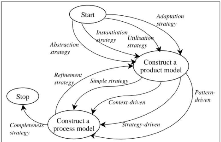
Our approach for Evolution-Driven ME uses meta-modelling as its underlying method engineering technique. Meta-modelling is known as a technique to capture knowledge about methods. It is a basis for understanding, comparing, evaluating and engineering methods. One of the results obtained by the meta-modelling community is the definition of any method as composed of a product model and a process model [Prakash99]. A product model defines a set of concepts, their properties and relationships that are needed to express the outcome of a process. A process model comprises a set of goals, activities and guidelines to support the process goal achievement and the action execution. Therefore, method construction following the meta-modelling technique is centred on the definition of these two models. This is reflected in the map representing the process model for Evolution-Driven ME (Figure 1) by two core intentions (the nodes of the map) Construct a product model and Construct a
process model. Stop Construct a product model Construct a process model Abstraction strategy Instantiation strategy Strategy-driven Context-driven Simple strategy Refinement strategy Completeness strategy Pattern-driven Start Utilisation strategy Adaptation strategy
A number of product meta-models [Grundy96, Hofstede93, Prakash02, Saeki94, Plihon96] as well as process meta-models [Jarke99, Rolland95, Rolland99] are available and our approach is based on some of them. This is shown in Figure 1 by several different strategies (the labelled edges) to achieve each of the two core intentions.
The construction of the product model depends of the ME goal that could be to construct a method:
• by raising (or lowering) the level of abstraction of a given model, • by instantiating a selected meta-model,
• by adapting a meta-model to some specific circumstances, • by adapting a model.
Each of these cases defines a strategy to Construct a product model, namely the
Abstraction, Instantiation, Adaptation and Utilisation strategies. Each of them is
supported by a guideline that consists in defining various product model elements such as objects, links and properties in different manner.
In our example, we use the Lyee Software Requirements Model (LSRM) model as a baseline paradigm model for the more abstract Lyee User Requirements Model (LURM) construction. In this case, the Abstraction strategy is the more appropriate one to Construct a product model as the ME goal is to rise the level of abstraction of the LSRM. For this reason, in the next section we detail and illustrate the guideline supporting product model construction following the
Abstraction strategy. This guideline is based on the abstraction of different
elements from the paradigm model (product and/or process model) into elements in the new product model and the refinement of the obtained elements until the new product model became satisfactory.
Process model must conform to the product model. Process steps, activities, actions always refer to some product model parts in order to construct, refine or transform them. This is the reason why in the map of Figure 1 the intention to
Construct a process model follows the one to Construct a product model. We
know that a process model can take multiple different forms. It could be a simple informal guideline, a set of ordered actions or activities to carry out, a set of process patterns to be followed, etc. In our Evolution-Driven process model (Figure 1) we propose four strategies: Simple, Context-driven, Pattern-driven and Strategy-driven to Construct a process model.
• The Simple strategy is useful to describe a uncomplicated process model that can be expressed as a textual description or a set of actions to execute. • The Context-driven process model is based on the NATURE process
modelling formalism [Jarke99, Rolland95]. According to this formalism, a process model can be expressed as a hierarchy of contexts. A context is viewed as a couple <situation, intention>. The situation represents the part
of the product undergoing the process and the intention reflects the goal to be achieved in this situation.
• Process model obtained following the Pattern-driven strategy takes the form of a Catalogue of Patterns. Each pattern identifies a generic problem, which could occur quite often in the product model construction, and proposes a generic solution applicable every time the problem appears. A generic solution is expressed as set of steps allowing to resolve the corresponding problem.
• Finally, the Strategy-driven process model, also called the Map [Rolland99, Benjamen99] (see the introduction of this paper), permits to combine several process models into one complex process model.
The process model of the LURM was defined following the Pattern-driven
strategy. A set of patterns has been defined to take into account different
situations in the user requirements definition. Each pattern provides an advice to capture and formulate requirements. The section 4 presents in detail and illustrates the guideline supporting the Pattern-driven strategy for the process model construction.
ABSTRACTION-BASED PRODUCT MODEL CONSTRUCTION
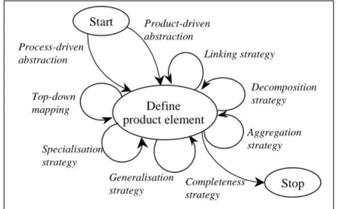
The Abstraction strategy for product model construction consists in defining a new product model representing the level of abstraction higher than the one of its paradigm model. As a consequence, the objective of the corresponding guideline is to support the construction of a product model as an abstraction of an other model (product or process or both of them). This guideline is also expressed by a map shown in Figure 2.
Aggregation strategy Decomposition strategy Generalisation strategy Define product element Product-driven abstraction Specialisation strategy Stop Completeness strategy Start Process-driven
abstraction Linking strategy
Top-down mapping
As the product model construction consists in the definition of its elements (objects, properties, links), there is only one core intention in this map called
Define product element. The achievement of this intention is supported by a set
of strategies. Two strategies named Product-driven abstraction and
Process-driven abstraction are provided to start the construction process. The first one
deals with the paradigm product model whereas the second one is based on the paradigm process model. The Product-driven abstraction consists in analysing the paradigm product model, identifying elements that could be represented in a more abstract form in the new model and defining these abstract elements. The
Process-driven abstraction proposes to analyse the paradigm process model and
to abstract some of its activities into the upper level ones. The product elements referenced by these more abstract activities must be integrated into the product model under construction. The concepts obtained following this strategy have to match concepts (or a collection of concepts) of the paradigm product model. The
Top-down mapping strategy can be applied to assure it. The Generalisation, Specialisation, Aggregation and Decomposition strategies are used to refine the
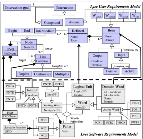
model under construction whereas the Linking strategy helps to connect different elements of this model obtained by applying different abstraction strategies. In order to illustrate the abstraction-based product model construction we present first our paradigm model, which is the Lyee Software Requirements Model depicted in Figure 3.
LogicalID Device Logical Unit LogicalID Device Logical Unit 1 1 1 NextpalletID
Routing Word Word WordID Domain Word L3 – condition L4 – formula Name Domain Domain Word L3 – condition L4 – formula Name Domain PRD1 POP1 Word in Pallet /Unit 1..* IntraSF PRDName PRD PRDName PRD SFID Scenario Function SFID Scenario Function W04 1 1..* PalletI Pallet PalletI Pallet InterSF Condition PCL1 PWT1 PCR1 PCR2 PBOX PNTN PNTR PNTA PNTE PNTC PNTD PNTM W02 W03 1 Action Word
Figure 3. The Lyee Software Requirements Model (LSRM).
The central concept in the LSRM is called a Word. A Word corresponds to a program variable: input words represent values captured from the external world whereas output words are produced by the system by applying specific formulae. Lyee Software Requirements processing mechanism applies a formulae to obtain output word from the given input words. The execution of formulae is controlled by the Process Route Diagram (PRD). A PRD is composed of Scenario Functions (SF), composed of Pallets which are made of
generates its own Words such as the Action words and Routing words. Action
words are used to control physical Input/Output exchanges in a Lyee program,
they implement application actions such as reading a screen, submitting a query to a database, opening or closing a file, etc. Routing words are used to distribute the control over various SFs of a PRD.
In order to comply with the LSRM paradigm, the LURM should be centred on a notion that abstracts from the concept of Word. Obviously Words required by the Lyee processing mechanism are not relevant at this level. On the contrary, the concern is only with Domain words. For that reason, the LSRM concept
Domain word is abstracted into LURM concept Item following the Product-driven abstraction strategy. The Specialisation strategy is applied in order to
specialise the Item into Output and Input to match the LSRM, which makes the difference between input and output words used in its processing mechanism. An Output is produced by the system whereas the Input is captured from the user. In the same manner, the Input is specialised into Active and Passive. The former triggers the system actions whereas the latter represents values captured from the user.
Next we analyse the LSRM process model. The paradigm process model deals with the generation of the Lyee program structure. The result of the obtained program execution must fit user’s requirements. In other words, it must allow the user to satisfy one of its goals. For that reason, in the upper user requirements level we need to reason with concepts allowing to identify these user goals and express how the user interacts with the system in order to achieve them. The Process-driven abstraction strategy allows us to define the notion of
Interaction representing the exchanges between the user and the system from the
user’s view point. An interaction is goal driven in the sense that the user asks the system to achieve the goal he/she has in mind without knowing how the system will do it. As a result, we associate an Interaction goal to each Interaction. The complexity of the interaction goal defines the complexity of the corresponding interaction. If the interaction goal can be decomposed into several atomic goals, the corresponding interaction can also be decomposed. Consequently, we specialise the interaction into Atomic and Compound thanks to the Specialisation strategy.
Action Word LogicalID Device Logical Unit SFID 1 1 1 NextpalletID
Routing Word Word
WordID Domain Word L3 – condition L4 – formula Name Domain PRD1 POP1 Word in Pallet /Unit 1..* IntraSF PRDName PRD Scenario Function Action Word 1 1..* PalletI Pallet InterSF Condition PCL1 PWT1 PCR1 PCR2 PBOX PNTN PNTR PNTA PNTE PNTC PNTD PNTM W02 W03 1 1 1..* {complete, or} source target PSG PSGName 0..* 0..* 1..* 1..* 1..* 1..* {complete, or} Defined Name Type 1 1..* Link Condition Continuous Multiplex {complete, or} Item Name Domain
Lyee User Requirements Model
Begin Intermediate Condition Formula Output Node NodeID Passive Compound Atomic Interaction goal
Winput Woutput Wresult Wend
End
Interaction
1
Lyee Software Requirements Model
Duplex W04 Input Active Action Word LogicalID Device Logical Unit LogicalID Device Logical Unit SFID 1 1 1 NextpalletID
Routing Word Word
WordID Domain Word L3 – condition L4 – formula Name Domain Domain Word L3 – condition L4 – formula Name Domain PRD1 POP1 Word in Pallet /Unit 1..* IntraSF PRDName PRD Scenario Function Action Word 1 1..* PalletI Pallet PalletI Pallet InterSF Condition PCL1 PWT1 PCR1 PCR2 PBOX PNTN PNTR PNTA PNTE PNTC PNTD PNTM W02 W03 1 1 1..* {complete, or} source target PSG PSGName PSG PSGName 0..* 0..* 1..* 1..* 1..* 1..* {complete, or} Defined Name Type 1 1..* Link Condition Link Condition Continuous Multiplex {complete, or} Item Name Domain
Lyee User Requirements Model
Begin Intermediate Condition Formula Output Condition Formula Output Node NodeID Node NodeID Passive Compound Atomic Interaction goal
Winput Woutput Wresult Wend
End
Interaction
1
Lyee Software Requirements Model
Duplex
W04
Input
Active
Figure 4. Lyee Product Models for Software Requirements and for User Requirements.
Now we need to define how the Interaction concept could be mapped to the concepts defined at the lower LSRM product model. Any of the LSRM concepts does not correspond the interaction of the LURM directly. However, the
Top-down mapping strategy suggests that an interaction could be expressed as a
combination of items that match the LSRM Domain word concept.
An Atomic interaction delineates a number of input and output data: the user provides some input and receives the output that corresponds the expected result. Therefore, the Decomposition strategy helps us to decompose every
Interaction into four kinds of Items that we call Winput, Woutput, Wresult and Wend.
Each of them represents:
• Winput: the input provided in the interaction,
• Wresult: the result of the goal achievement,
• Woutput: the output displayed to the user,
Then we consider the concept of Logical unit (from LSRM) that represents a coherent set of words used in the same processing (reading or writing) and constrained by the same physical device (database, file, screens, etc.) used by the program. The concept of Defined abstracts this notion in order to aggregate logically related Items processed together and constrained by the same conceptual device. One Defined can be specialised into one or more Logical
units. For example, one Defined corresponding to a conceptual screen can be
implemented by two physical screens requiring four Logical units. To sum up, the Product-driven abstraction strategy followed by the Linking strategy allows us to create the Defined concept and to connect it with the Items composing it. Similarly, the concept of PSG, the Precedence Succedence Graph was obtained by abstraction of the PRD concept from the paradigm product model. A PSG specifies the ordering conditions between Defineds as the PRD do it with Words. The Decomposition strategy was applied to represent the structure of the PSG as a graph composed of Links and Nodes. Following the Top-down mapping strategy we recognize that the Link matches the LSRM InterSF concept that captures different links between the Scenario Functions in a PRD whereas the
Node corresponds the Scenario Function concept. Thanks to the Specialisation
strategy the Link was specialised into Duplex, Continuous and Multiplex whereas the Node was specialised into Begin, End and Intermediate. Every
Defined is an intermediate link in at least one PSG. Figure 4 summarizes the
abstraction process from the lower LSRM into upper LURM.
PATTERN-BASED PROCESS MODEL CONSTRUCTION
The Pattern-based process model construction strategy is based on the concept of pattern, which has been introduced by Alexander in architecture [Alexander77] and borrowed by IT engineers to capture software design knowledge [Gamma94, Coad96, Coplien95, Fowler97] as well as method engineers to capture reusable method knowledge [Rolland96, Deneckere98]. According to Alexander, a pattern refers to ‘a problem which occurs again and again in our environment and describes the core of the solution to that problem, in such a way that you can use this solution a million times over, without ever doing it the same way twice’. The key idea of a pattern is thus, to associate a
problem to its solution in a well identified context.
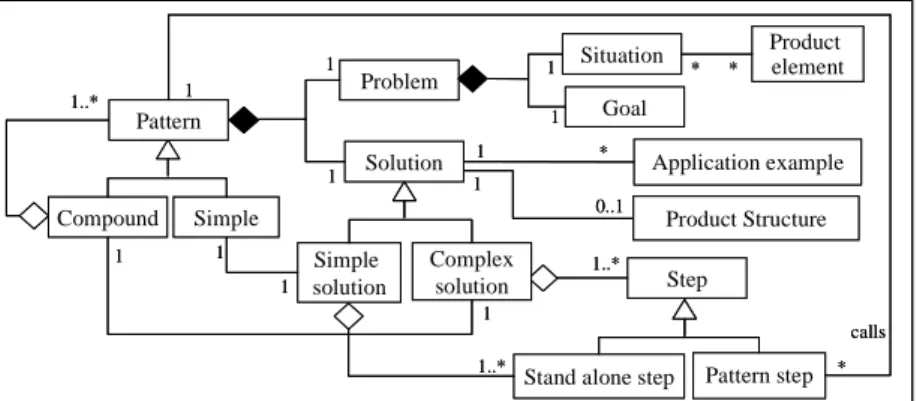
Figure 5 shows the pattern meta-model. The problem refers to the situation in which pattern can be applied and the goal to achieve in this situation. The situation is characterised by a set of product elements. The solution is represented by a set of steps to realise in order to resolve the problem. A pattern can be simple or compound. The solution of a compound pattern contains steps which call other patterns and are named pattern steps in the contrary to stand
Problem Solution Compound Simple Situation Goal 1 1 1 1 * 1..* Product element Application example
Stand alone step Pattern step Step 1..* 1 Pattern 0..1 1 * Complex solution Simple solution * 1 1 1 1 1..* 1 * calls Product Structure Problem Solution Compound Simple Situation Goal 1 1 1 1 * 1..* Product element Application example
Stand alone step Pattern step Step 1..* 1 Pattern 0..1 1 * Complex solution Simple solution * 1 1 1 1 1..* 1 * calls Product Structure
Figure 5. Pattern meta-model.
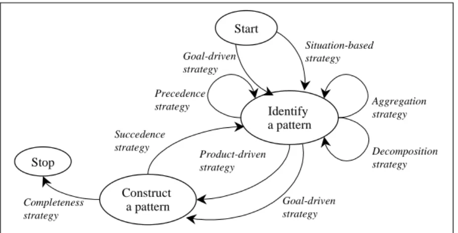
The process model for pattern construction is defined by a map based on two core intentions Identify a pattern and Construct a pattern (Figure 6). To Identify
a pattern means to identify a generic problem. As shown in Figure 6, the
problem identification can be based on the discovery of a typical situation or a generic goal in the method context. The two cases are respectively supported by two strategies: Situation-based and Goal-driven. The Aggregation strategy allows to combine several patterns into a compound one in order to propose solutions for complex problems whereas the Decomposition strategy deals with the identification of sub-problems, which could also be considered as generic ones. The identification of a new pattern situation advises us to consider that there must be another pattern creating this situation. This case is supported by the Precedence strategy.
To Construct a pattern means to formalise its problem (the situation and the goal), to define the solution to its problem as a set of steps to execute, to define its template and to give some examples of its application. Two strategies named
Product-driven and Goal-driven are provided for this purpose (Figure 6). The
guideline supporting the Product-driven strategy is based on the transformation of the product elements from the pattern situation into the product element defined as the pattern target (pattern goal target). The Goal-driven strategy deals with the pattern goal reduction into a set of atomic actions to be carried out in order to achieve this goal. The Succedence strategy considers that the result product obtained by applying an already defined pattern can be considered as a potential situation for the definition of an other pattern.
Stop Identify a pattern Aggregation strategy Goal-driven strategy Product-driven strategy Succedence strategy Completeness strategy Decomposition strategy Start Situation-based strategy Precedence strategy Goal-driven strategy Construct a pattern
Figure 6. Pattern-based process model construction.
In order to define the patterns supporting LURM construction, we need to identify typical situations (the problem) in the Lyee user requirements capture (the context) and to define the corresponding guidelines (the solution) assisting in the requirements elicitation and formulation. As shown in Figure 6, we can start the pattern identification process following one of two strategies:
Goal-driven or Situation-based. The guidelines supporting these two strategies
supplement each other and there is no pre-established order to realise them. In our case, we start the pattern identification process following the Goal-driven strategy and we consider the core LURM objective ‘to define user
requirements’. As stated in the previous section, the LURM defines user
requirements as user-system interactions. Therefore, we founded our reasoning on the notion of atomic interaction and investigate the possibility to identify generic activities for requirements capture within this context. We deduce that the requirements capture related to an atomic interaction comprises four activities that can be considered as four potential pattern goals:
• to start the interaction (Formulate To Start requirements), • to perform the action (Formulate To Act requirements), • to prepare the output (Formulate To Output requirements) and, • to end the interaction (Formulate To End requirements).
Each of these activities is linked to the item typology introduced in section 0 as each activity is associated to one type of Item:
• the Formulate To Start requirements deals with the capture of Winput,
• the Formulate To Act requirements is concerned by the calculation of Wresult,
• the Formulate To Output requirements shall help eliciting and defining Woutput,
Each requirement activity is concerned with the elicitation and definition of these Items, their grouping in Defineds and the positioning of those in the interaction PSG.
Next, we select the Situation-based strategy to Identify a pattern (Figure 6) and consider the possible situations in which these goals are relevant. For instance, we distinguish two different situations dealing with the capture of Winput: either
the input value does not exist and is directly captured from the user or it exists in a database or a file and is captured from this container. As a consequence, we identify two patterns having the same goal Formulate To Start requirement but dealing with different situations Input capture from the user and Input capture
form the internal device. We call these two patterns respectively Immediate Start
and Prerequisite for Start.
In the same manner we identify two generic situations for each of the four generic goals and identify so eight generic patterns. Table 1 characterises the discovered patterns. Each of these 8 patterns deals with one single requirement activity whereas to get the complete set of requirements for a given problem, the requirements engineer has to perform one of each type of activity. The complete set of requirements requires that each of the following be performed once: ‘To
start’, ‘To Act’, ‘To Output’ and ‘To End’. To obtain advice on this, a new
pattern, Pattern P9, is introduced thanks to the Composition strategy.
The Succedence strategy for pattern identification suggests us to think about the construction of a compound interaction that could be based on the iteration of an atomic interaction creation guided by the pattern P9. As a result, we identify a new pattern for a compound interaction formulation that we call P10 Complex
Composition (Table 1).
Goal Situation Characterisation Pattern name
Formulate To Start requirements
W input are captured directly from the user. P2 Immediate
Start Formulate To Start
requirements
Winput are retrieved from a database or a file. P3 Prerequisite
for Start Formulate To Act
requirements
Wresult are calculated by a simple formulae,
which does not require the calculation of the intermediate words.
P1 Simple Word Formulate To Act
requirements
Wresult are calculated by a complex formulae,
which requires the calculation of the intermediate words and possibly the access to the data in a file or a database.
P8 Complex Word
Formulate To Output requirements
There is no obstacle neither in the capture of Winput nor in the production of Wresult.
P6 Single Output Formulate To Output
requirements
A number of different cases of output production shall be considered due to possible obstacles either in the capture of Winput or in the production of Wresult.
P7 Multiple Output
Formulate To End requirements
The interaction ends normally without additional internal activity.
P4 Simple End Formulate To End
requirements
Some internal activity shall be performed such as storing part or the totality of Woutputs.
P5 Compound End
Formulate requirements for an atomic
interaction
The interaction goal is atomic. P9 Simple
Composition Formulate requirements
for a compound interaction
The interaction goal is compound. P10 Complex
Composition
Table 1. Characterisation of the identified patterns.
Let’s illustrate now the construction of a pattern solution. In our example, the pattern solution takes the form of a sequence of rules to be applied by the engineer. Each of them mentions an action to perform like ‘construct a
hierarchy of intermediate words involved in the calculation of the result word’.
Most of these actions are identifying a requirement, i.e. referring to an element of the meta-model (LURM): Defined, Item, Node and Link in the PSG, as for example ‘introduce a defined of type screen’.
Begin Node1 <<bind>> (Type = Screen) source target 1..* 1 1 1 1 PSG : PsgName Continuous <Null> Condition Intermediat e Node2 S inputDefined Defined Name Type Type Passive Name Domain Begin Node1 Begin Node1 <<bind>> (Type = Screen) source target 1..* 1 1 1 1 PSG : PsgName Continuous <Null> Condition Continuous <Null> Condition Intermediat e Node2 Intermediat e Node2 S inputDefined S inputDefined Defined Name Type Type Defined Name Type Type Passive Name Domain Passive Name Domain
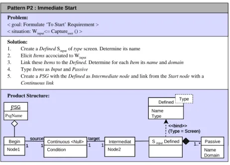
Pattern P2 : Immediate Start
Problem:
< goal: Formulate ‘To Start’ Requirement > < situation: Winput<= Captureuser() >
Solution:
1. Create a Defined Sinputof type screen. Determine its name 2. Elicit Items accociated to Winput
3. Link these Items to the Defined. Determine for each Item its name and domain 4. Type Items as Input and Passive
5. Create a PSG with the Defined as Intermediate node and link from the Start node with a
Continuous link
Product Structure:
Figure 7. Pattern P2 : Immediate Start.
As an example we propose the construction of the pattern P2 following the
Product-driven strategy. The objective of this pattern is to prepare a user-system
interaction. The Product-driven strategy advises to instantiate the meta-model elements necessary to achieve the pattern goal. In this case we need to
necessary for the input values capture. As a consequence, the actions to perform should be:
• to create the Defined for the necessary input values capture, • to define an Item to each input value,
• to link the Items to the Defined, • to type Items as Input and Passive and • to create the relevant part of the PSG.
Next we need to define the pattern product structure. The pattern product structure is an instance of the meta-model representing the configuration of concepts to be instantiated in any application. In the case of the pattern P2, a
PSG must be created containing a Begin node, a Continuous link, an Intermediate node corresponding to the Defined of type screen (called Sinput)
composed of the elicited Items. Figure 7 shows the pattern P2, its problem, solution and template.
In the same manner we construct all the patterns from P1 to P8. The pattern P9 can be constructed following the Goal-driven strategy, which advises to decompose the principal goal into sub-goals until the atomic actions had been obtained. Thus, the objective of the pattern P9 ‘Formulate requirement for an
atomic interaction’ can be decomposed into four sub goals ‘Formulate To Start requirement’, ‘Formulate To Act requirement’’, ‘Formulate To Output requirement’, ‘Formulate To End requirement’ in this order. As there are always
two patterns that are candidate to help achieving the goal, it is necessary to examine the situation first. As pattern situations are exclusive, the choice of the relevant pattern to apply is easy. The obtained pattern is a compound one. It is shown in Figure 8.
Pattern P9 : Simple Composition
Problem:
< goal: Formulate requirement for an atomic interaction > < situation: The interacion goal is atomic >
Solution: 1. Formulate To Start equirement 2. Formulate To Act requirement 3. Formulate To Output requirement 4. Formulate To End requirement
Formulate requirement for an atomic interaction
Apply P2 Apply P3 Apply P1 Apply P8 Apply P6 Apply P7 Apply P1 Apply P8 Determine the situation to End Apply pattern Determine the situation to Output Apply pattern Determine the situation to Act Apply pattern Determine the situation to Start Apply pattern
Figure 8. Pattern P9: Simple Composition.
Finally, the pattern P10 deals with the compound interaction. The goal to be achieved is to get a complete and coherent requirement formulation for a
compound interaction. This pattern should give an advice on how to decompose a compound interaction into atomic interactions to which the pattern P9 should be applied. In fact, the pattern helps in recognising that the interaction is not an atomic one in the first place.
Each of ten patterns captures a requirement situation and guides the formulation of the requirement in compliance with the requirement meta-model. The ten patterns will be applied again and again in the different software projects using Lyee. Even though actual situations are different from one project to another, each of them should match one pattern situation and the pattern will bring the core solution to the requirements capture problem raised by this situation.
CONCLUSION
In this paper we propose an approach for evolution-driven method engineering. Evolution in this case means that we start method engineering with an existing paradigm model (model or model) and we obtain a new model (or meta-model) by abstracting, transforming, adapting or instantiating this paradigm model. Our process model for evolution-driven ME captures these various evolution ways as different strategies to create the product part of the model under construction. The corresponding process part construction is also supported by a set of strategies the selection of which depends on the process nature and complexity. Every strategy is supported by a guideline assisting method engineer in his or her method evolution task.
The flexibility offered by the map formalism that we use to express our Evolution-Driven ME process model allows us to include other ways for method evolution in a rather simple manner. They can be integrated as different strategies to satisfy the intention Construct a product model and Construct a
process model.
In this paper we present the evaluation of our approach by the LURM construction as evolution of the LSRM. The Abstraction strategy have been used to Construct a product model while the Pattern-driven strategy was applied to
Construct a process model. In this paper we present these two strategies in more
detail and illustrate their application. Our future preoccupation is to evaluate other proposed method evolution strategies as well as to validate it through real projects.
REFERENCES
Alexander, C., Ishikawa, S., Silverstein, M., Jacobson, M., Fiksdahl-King, I., Angel, S. (1977). A Pattern Language. Oxford University Press, New York.
Benjamen, A. (1999). Une Approche Multi-démarches pour la modélisation des
démarches méthodologiques. Unpublished doctoral dissertation,
University of Paris 1 – Sorbonne.
Brinkkemper S., Saeki, M. & Harmsen, F. (1998). Assembly Techniques for Method Engineering. Proceedings of the 10th International
Conference on Advanced Information Systems Engineering, CAiSE’98. Pisa Italy.
Coad, D., North, D. & Mayliefd, M. (1996). Object Models – Strategies,
patterns and applications, Yourdon Press Computing Series, 1996.
Coplien, J.O. & Schmidt, D.O. (Eds.). (1995). Patron Languages of Program
Design. Addison-Wesley, Reading, MA.
Deneckere, R. & Souveyet, C. (1998). Patterns for extending an OO model with temporal features. Proceedings of the International Conference on
Object-Oriented Information Systems, OOIS'98, Springer-Verlag,
Paris (France).
Fowler, M. (1997). Analysis Patterns : reusable objects models, Addison-Wesley.
Gamma, E., Helm, R., Johnson, R. & Vlissides, J. (1994). Design Patterns :
Elements of Reusable Object-Oriented Software, Addison-Wesley.
Grundy, J.C. & Venable, J.R. (1996), Towards an Integrated Environment for
Method Engineering. In Chelenges and Strategies for Research in
Systems Development. W.W. Cotterman and J.A. Senn (Eds.), John Wiley & Sons. Chichester, pp.45-62.
Harmsen A.F., Brinkkemper, S. & Oei, H. (1994). Situational Method Engineering for Information System Projects. In Olle T.W. and A.A.
Verrijn Stuart (Eds.), Mathods and Associated Tools for the Information Systems Life Cycle, Proc. of the IFIP WG8.1 Working
Conference CRIS'94, pp. 169-194, North-Holland, Amsterdam. Harmsen, A.F. (1997). Situational Method Engineering. Moret Ernst & Young. Hofstede, A.H.M. Ter. (1993). Information modelling in data intensive domains,
Dissertation, University of Nijimegen, The Netherlands.
Jarke M., Rolland, C., Sutcliffe, A. & Domges, R. (1999). The NATURE
requirements Engineering. Shaker Verlag, Aachen.
Kumar, K. & Welke, R.J. (1992). Method Engineering, A Proposal for Situation-specific Methodology Construction. In Systems Analysis
and Design : A Research Agenda, Cotterman and Senn (eds), Wiley,
pp257-268, 1992.
Negoro, F. (2001a). Methodology to Determine Software in a Deterministic Manner. Proceedings of ICH, Beijing, China.
Negoro, F. (2001b). A proposal for Requirement Engineering. Proceedings of
ADBIS, Vilnius, Lithuania, 2001.
Plihon, V., Ralyté, J., Benjamen, A., Maiden, N.A.M., Sutcliffe, A., Dubois, E., Heymans, P. (1998). A Reuse-Oriented Approach for the Construction of Scenario Based Methods. Proceedings of the
International Software Process Association's 5th International Conference on Software Process (ICSP'98), Chicago, Illinois, US.
Plihon, V. (1996). Un environnement pour l'ingénierie des méthodes, Unpublished doctoral dissertation, University of Paris 1 – Sorbonne. Prakash, N. & Bhatia, M. P. S. (2002). Generic Models for Engineering
Methods of Diverse Domains. Proc. of CAISE’02, Toronto, Canada, LNCS Volume 2348, pp. 612., 2002.
Prakash, N. (1999). On Method Statics and Dynamics. Information Systems. Vol.34 (8), pp 613-637.
Punter H.T. & Lemmen, K. (1996). The MEMA model : Towards a new approach for Method Engineering. Information and Software Technology, 38(4), pp.295-305.
Ralyté, J. & Rolland, C. (2001a). An Assembly Process Model for Method Engineering. Proceedings of the 13th International Conference on
Advaced Information Systems Engineering, CAISE’01, Interlaken,
Switzerland.
Ralyté, J. & Rolland, C. (2001b). An approach for method reengineering.
Proceedings of the 20th International Conference on Conceptual Modeling, ER2001, Yokohama, Japan.
Ralyté, J. (1999). Reusing Scenario Based Approaches in Requirement
Engineering Methods: CREWS Method Base. Proc. of the First
International Workshop on the Requirements Engineering Process - Innovative Techniques, Models, Tools to support the RE Process, Florence, Italy, September.
Rolland C., Plihon, V. & Ralyté, J. (1998). Specifying the reuse context of Scenario Method Chunks. Proceedings of the 10th International
Conference on Advanced Information System Engineering
(CAISE'98), Pisa, Italy.
Rolland, C. & Prakash, N. (1996). A proposal for context-specific method engineering. Proceedings of the IFIP WG 8.1 Conference on Method Engineering, Chapman and Hall, pp 191-208, Atlanta, Gerorgie, USA.
Rolland, C., Prakash, N. & Benjamen, A. (1999). A Multi-Model Vew of Process Modelling. Requirements Engineering Journal, Vol. 4 (4), pp169-187.
Rolland, C., Souveyet, C. & Moreno, M. (1995). An Approach for Defining Ways-of-Working, Information Systems Journal, 1995.
Saeki, M. & Wen-yin, K. (1994). Specifying Software Specification and Design Methods. Proceedings of the International Conference on Advaced
Information Systems Engineering, CAISE’94, LNCS 811, Springer
Verlag, pp 353-366, Berlin, 1994
Saeki, M., Iguchi, K., Wen-yin, K., Shinohara, M. (1993). A meta-model for representing software specification & design methods. Proc. of the
Song, X. (1997).Systematic Integration of Design Methods. IEEE Software, 1997.
Van Slooten K. & Brinkkemper, S. (1993). A Method Engineering Approach to Information Systems Development. In Information Systems
Development process, N. Prakash, C. Rolland, B. Pernici (Eds.),
Elsevier Science Publishers B.V. (North-Holand).
Van Slooten, K. & Hodes, B. (1996). Characterising IS development project. Proceedings of the IFIP WG 8.1 Conference on Method Engineering, Chapman and Hall, pp 29-44.