Science Arts & Métiers (SAM)
is an open access repository that collects the work of Arts et Métiers Institute of Technology researchers and makes it freely available over the web where possible.
This is an author-deposited version published in: https://sam.ensam.eu
Handle ID: .http://hdl.handle.net/10985/7918
To cite this version :
Serge MOUTON, Denis TEISSANDIER, Patrick SEBASTIAN, JeanPierre NADEAU
-Manufacturing requirements in design: The RTM process in aeronautics - In: 9th international conference on flow processes in composite materials. FPCM-9 [Multimédia multisupport] : 8-10 July, 2008, Canada, 2008-07 - 9th international conference on flow processes in composite materials. FPCM-9 [Multimédia multisupport] : 8-10 July, 2008 - 2008
Any correspondence concerning this service should be sent to the repository
MANUFACTURING REQUIREMENTS IN DESIGN: THE
RTM PROCESS IN AERONAUTICS
S. Mouton 1, 3, D. Teissandier 1, P. Sébastian 1, J. P. Nadeau 2
1 Université Bordeaux 1; Cours de la Libération 33405 Talence cedex France
[email protected]; Email: [email protected]
2 Arts et Métiers Paris Tech; Esplanade des Arts et Métiers 33405 Talence Cedex France;
Email: [email protected]
3 Corresponding author’s Email: [email protected]
SUMMARY: A sub-unit of an aeronautical structure (fuselage, fin, wing, etc.) consists of a set
of components fixed rigidly together. One of today’s major industrial challenges is to produce these sub-units out of composite materials in order to increase the level of integration and reduce mass and cost. This article describes a procedure to assist in the industrialisation of aeronautical components produced from composite materials in a design for manufacturing context. In a multi-expertise approach, the problem of optimising integration is combined with the feasibility of injection for the Resin Transfer Molding process. This approach then takes into account admissible manufacturing deviations, defined from a classification of the structure parts. The limits set for admissible deviations guarantee the mechanical behaviour of the assembled component and the requirements of the assembly as a whole. Finally, an industrialisation solutions space is defined. A constraint satisfaction problem solver is used to carry out this research with a spar from a horizontal plane in an aircraft used to illustrate the procedure.
KEY WORDS: Resin Transfer Molding (RTM), assembly, residual stresses, industrialisation,
strain, geometric specification for non-rigid parts, Constraint Satisfaction Problem (CSP) solver
INTRODUCTION
When taking industrialisation into account in the design cycle [1-3] two distinct and complementary aspects must be considered: technical feasibility and economic feasibility. The technical feasibility of the RTM process imposes specific shapes and dimensions. Moreover, the RTM process can cause strain as parts are removed from the moulds, caused by the architecture of the laminate and the great complexity of physical phenomena around the parameters governing the RTM process. These strains are characterised by manufacturing deviations from which the true geometry of the part can be defined in relation to its design geometry (CAD model). In order
FPCM-9 (2008)
The 9th International Conference on Flow Processes in Composite Materials
Montréal (Québec), Canada 8 ~ 10 July 2008
to integrate a part into a sub-unit, it is often necessary to distort it. This is due to the highly over-constrained architecture of sub-units for aeronautical structures. If a part undergoes strain when it is integrated into a sub-unit this gives rise to mechanical stresses which could mean that the functional requirement of the sub-unit is not respected and could affect the mechanical behaviour of the part itself. With a classification of the structure components it is possible to identify those components for which significant strains are acceptable. These must then be quantified in order to define the induced stresses in the component and the stresses added to the sub-unit during the assembly phase. The aim of our study is to integrate these stresses generated in the part and the sub-unit by the assembly operation into the choices in the flow-process grid. The problems involved in integrating industrialisation into the design cycle are already taken into consideration in the expert rules provided by many aircraft manufacturers. These rules are the result of work by experts within the company. They have a limited area of validity and restrict the area available for design investigation. In this study our aim is to develop knowledge models in order to be more effective in finding the level of integration of the parts into a sub-unit, thus reducing mass and controlling costs.
CLASSIFICATION OF COMPOSITE STRUCTURAL COMPONENTS
A classification of the structural components identifies two types of component: type_1 and type_2. Each manufactured part is in contact with other parts in a sub-unit, which are called the adjacent parts. The adjacent parts will exert efforts via the contact surfaces, generating mechanical assembly stresses which are then distributed throughout the manufactured part and the sub-unit. These stresses can compensate for manufacturing deviations to a greater or lesser extent, in correlation with the strain caused by the shaping process. For type_1 components, mechanical assembly stresses have a great influence on the manufacturing deviations. Thus a fairly large defect can be specified in the general shape of the part in its free state. Stresses are characterised by geometric specifications associated with a stress condition [4], and the unit is shown on the definition of the part. However, mechanical assembly stresses should not exceed a certain maximum limit, determined by two criteria:
− one criterion intrinsic to the manufactured part: mechanical behaviour,
− one criterion intrinsic to the sub-unit: stress condition beyond which the sub-unit will be too distorted, thus jeopardising respect for certain functional requirements.
For type_2 components, assembly stresses have very little influence on strain generated by the process. As a result, manufacturing deviations cannot be compensated by contacts from adjacent parts. This results in a specification for a much more serious default in the general shape of the part in its free state than for the type_1 components. When the expert rules are applied to type_2 components, these components have symmetry from a geometrical point of view and also from the point of view of laminate architecture. This type of design limits the risk of strain but does not allow for the optimisation of mass and function integration. The use of specifications for each stress condition often proves to be unhelpful. In the design phase this distinction between groups of components will influence the laminate definition.
LAMINATE DESIGN AND RTM PROCESS
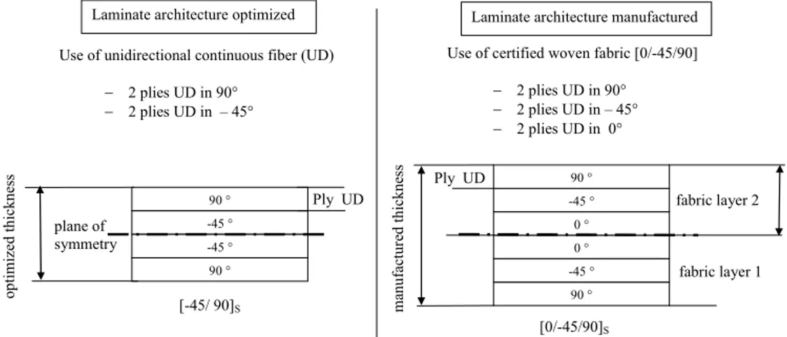
For parts with large dimensions, matter needs to be put in the places where stresses will occur hence the laminate is organised by zone. This is indispensable in order to reduce component mass. Each zone is a stack of fibers, with the juxtaposition of the zones ensuring variations in thickness. Each zone is defined by its shape, the number of fibers it contains and the orientation of each fiber in relation to a common frame of reference. Designing by zone in this way is linked with expert rules. In one of his papers, Gay describes an example of design by zone [5]. This organisation defines the optimised architecture for the laminate. To limit strain due to shaping, the unidirectional fibers are positioned using ply symmetry. Ply symmetry is the symmetrical arrangement of the stacks according to a design where the laminate is divided into two halves. In the RTM process, the stiffening pieces used are generally woven. This woven stiffener has a number of unidirectional continuous fibers or associated and oriented materials. In aeronautics, cost and delays in certifying composite material constituents can limit the types of stiffener that can be used. During the laminate design phase, an optimised architecture is defined for the laminate, however, using certified woven stiffeners may be the source of deviations between the optimised laminate architecture and the manufactured laminate architecture, and Fig. 1 illustrates this using an example showing the differences. To simplify the diagram, this example does not follow the rules of technological minimum [5]. This difference between the architectures impacts on the thickness of the laminate, and hence on the mass of the component and may give rise to strains. Organisation of the stacking is defined in a second phase in order to reach a compromise between reduction in mass and symmetry of stacking. We plan to use asymmetrical stacking for type_1 components. This asymmetry produces strains that are acceptable for type_1 components although not for type_2 components. Moreover, strains associated with using the RTM process are not caused solely by the architecture of the laminate. The different heat expansions of the constituent parts and the thermal cycles of polymerisation can also produce strain as parts are removed from the mould [6].
Laminate architecture optimized
-45 ° 90 °
90 ° -45 °
Use of unidirectional continuous fiber (UD) − 2 plies UD in 90°
− 2 plies UD in – 45°
Laminate architecture manufactured
0 ° 0 ° -45 ° 90 ° -45 ° optimi ze d th ickness ma nufactur ed thickne ss plane of symmetry fabric layer 2 fabric layer 1 [-45/ 90]S [0/-45/90]S Ply UD Ply UD
Use of certified woven fabric [0/-45/90] − 2 plies UD in 90° − 2 plies UD in – 45° − 2 plies UD in 0°
90 °
Fig. 1 Optimized and manufactured laminate architectures.
DIFFERENT GEOMETRIES FOR A TYPE_1 COMPONENT
During the industrialisation phase for a type_1 component, the aim is to estimate acceptable limits for manufacturing deviations in the RTM process according to the maximal limit of
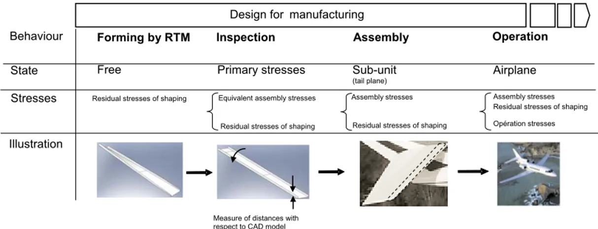
mechanical assembly stresses. As well as specifying the acceptable limits for manufacturing deviations, industrial practices and ISO standards for geometric specifications also lay down a stress condition that derives either from the criterion defined for manufactured parts or the criterion for the sub-unit, as defined in the paragraph above, “Classification of structural composite components”. To quantify the strains associated with the shaping process we will first define several component states. These definitions will be based on behaviours of the product in the design cycle. Each state is associated with specific stress conditions (Fig. 2). Free state [4]: the manufactured component is subjected only to the action of gravity and to the residual stresses of the shaping process. The Sub-unit state corresponds to the mechanical stresses of assembly: the manufactured part is integrated into the sub-unit to which it belongs. Lastly, we define an Airplane state where the aircraft is in normal operational conditions. The Primary stresses state corresponds to the inspection stage, where manufacturing deviations in the part must respect the two criteria: assembly requirements and mechanical behaviour.
Fig. 2 Different states of a type_1 component.
INDUSTRIALISATION MODEL AND SOLUTIONS SPACE
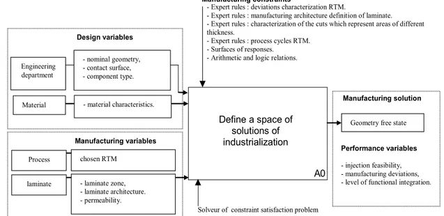
The level of functional integration of an aeronautical sub-unit is determined by the ratio of the number of components assembled to the number of functions the sub-unit must carry out. This level is optimal if the sub-unit consists of a single component. The architecture of a component can give rise to several industrialisation solutions all of which would enable the component to be produced and to carry out the functions for which it has been designed. Our model must therefore be able to define a group of solutions which are compatible with the multi-expert stresses used. The stresses are formalised according to expert knowledge derived from the engineering and design department and the industrialisation departments and take the form of expert rules, arithmetic and logic relations. If expert software tools are used, then experimental designs can be set up from which response surfaces models can be generated. Each solution is defined by a free state. This set of solutions forms the industrialisation solutions space. The modelling variables (Fig. 3) are divided into four groups: design variables: engineering department and material (in the aeronautics industry this group is constrained by certification); industrialisation variables: process and laminate, in our study the sub-group process is limited to RTM [7];
Operation Airplane Assembly Sub-unit (tail plane) Assembly stresses Forming by RTM Free
Design for manufacturing
Inspection
Equivalent assembly stresses Behaviour
State Primary stresses
Stresses Assembly stresses
Residual stresses of shaping Opération stresses
Measure of distances with respect to CAD model Residual stresses of shaping
Illustration
- nominal geometry, - contact surface, - component type. A0 Define a space of solutions of
industrialization Performance variables - injection feasibility, - manufacturing deviations, - level of functional integration.
Manufacturing variables
Solveur of constraint satisfaction problem
Design variables
Manufacturing constraints
Engineering department
Material - material characteristics.
laminate - laminate zone, - laminate architecture. - permeability.
- Expert rules : deviations characterization RTM.
- Expert rules : manufacturing architecture definition of laminate. - Expert rules : characterization of the cuts which represent areas of different thickness.
- Expert rules : process cycles RTM. - Surfaces of responses.
- Arithmetic and logic relations.
Geometry free state
Manufacturing solution
Process chosen RTM
performance variables: functional integration, feasibility injection and manufacturing
deviations; auxiliary variables: set of variables needed to define constraints [8].
The resolution strategy based on exploring a solutions space produces value domains {D} associated with the variables {V}, these may be design variables, industrialisation variables and performance variables. Each solution thus defined will satisfy all the constraints of the problem {C} and will be formalised by the free geometric state of the component. This set of variables and constraints represents a constraint satisfaction problem. Values associated with the performance variables (performance indicators) will guide choice in the solutions space. Due to the heterogeneity of the variables being manipulated, the use of multi-expert constraints and the exploration of a solutions space, we considered using a constraint satisfaction problem solver [9].
Fig. 3 Modelling to determine industrially feasible solutions (IDEF0 formalism).
Fig. 4 shows the processing of variables and their values, resulting in an industrialisation solution. The variables below are generally sets of elementary variables which define a parameter that is relevant to the design cycle for the component:
− nominal geometry: defined by a set of variables associated with the initial shapes and dimensions of the component. A second set of variables defines the shapes, dimensions and positions of additional geometries to the component’s initial geometry,
− contact surface: defined by a set of variables describing the shapes, dimensions and positions of the contact surfaces, the number of variables may change with the level of functional integration,
− component type: this variable has two values (type_1 or type_2),
− material characteristics: defined by a set of variables describing the type of stiffener and the type of resin,
− laminate zone: defined by a set of variables describing the different shapes that are possible at the ends of the zones,
− laminate architecture: defined by a set of variables describing the stacking of the fibers, independently of the type of stiffener and the type of component,
− permeability: defined by a set of variables describing the types of resin flow through the preform in the tools,
− injection feasibility: defined for each solution by a variable whose value is a function of a porosity rate,
− manufacturing deviations: defined for each solution by a variable whose value is a function of the stress condition,
− functional integration: defined for each solution by a variable whose value is assessed based on the number of functions carried out by the component.
A constraint satisfaction problem solver is an effective procedure to apply to an industrialisation model, taking into account causality when processing the variables and then prioritising these variables. In terms of digital processing, our work consisted of proposing a modelling framework
- l am ina te zon e, - l am inat e a rch itect ur e. - E xp ert ru les : m an uf act ur ing ar ch itect ur e def ini tio n o f lam ina te. - E xp ert ru les : c har act eri zat ion RT M geo met ry . - E xp ert ru les : c har act eri zat ion of th e cut s wh ich rep res en t ar eas of di ffere nt thi ck nes s. - A rit hmet ic an d l og ic re lat ion s Ex pe rt tool com pos ite Def ine m an uf ac turi ng gaps - m ate rial ch arac ter ist ics . - E xper t r ules : de viat ion s c har act eri zat ion RT M . - R ela tio ns ar ithm eti c an d l ogi c Ex pe rt tool C alc ula tin g stru ctu re De fin e inje ctio n fe as ibi lity - p erm ea bili ty - S ur faces of respo ns es - A rit hm eti c an d l og ic rel ati on s Ex pe rt too l R TM In ject ion feas ibil ity M an uf ac tur ing devi ati ons Geo met ry fr ee sta te Desi gn var iabl es Man uf ac turing va riab les In dic ator lev el of fu nc tio na l int eg rat ion In dicat or in ject ion feas ibi lit y In dic ator M an uf ac turi ng de viat ions A0 So lveu r o f co nst rai nt sat isf act ion pr ob lem Pe rfor m an ce va riabl es De fin e l ami na te - n om ina l geo me try , - c on tact su rface, - c om po nen t ty pe
. Fig. 4 Meta-model to determine
industrialisation solutions (IDEF0 formalism).
(meta-model). Using meta-models, the performance of constraint satisfaction problem solvers can be improved in terms of calculation time and solution quality [10]. In our study, three stages were necessary to finally define a solution:
− definition of two characteristics relating to the laminate and one relating to the geometry of the component: definition of the stacking of the laminate according to the nature of the stiffener and the component type and definition of the geometry of the end of the fibers that make up the zones, definition of the nominal geometry of the component adapted to the process (joint radius, maximum dimensions, etc.).
− estimation of solution injectability using a software tool. For this stage, permeability values must be defined, these values will be obtained experimentally or semi-analytically. Injectability can be estimated by measuring porosity rates from injection simulations.
− definition of admissible manufacturing deviations which depend on the condition imposed on the constraint when defined industrially. To obtain this value, solution injectability must be greater than a fixed percentage of porosity rates; if this is not the case the solution is abandoned. Results from the first stage combined with the characteristics of the material will produce a definition of manufacturing deviations. This definition guarantees the mechanical behaviour of the component and of the structure into which it will be inserted.
One of the major difficulties found with this type of constraint satisfaction problem is that the set of variables, the set of constraints and the set of domains may evolve during the solving process. This is traditionally identified as a dynamic constraint satisfaction problem. Moreover, the value domains associated with the variables may change across continuous and discrete spaces. Our problem falls into the category of dynamic mixed constraint satisfaction problem [11].
INDUSTRIAL APPLICATION
This study is part of a collaborative work with the Dassault-Aviation company. We chose to work on a component currently produced by RTM, i.e., the spars that make up the horizontal plane of the Falcon [12]. Assembly of the sub-unit that includes the spars is done using a rigid assembly tool, the spars are type_1 components. The spars are made of carbon fibre and epoxy resin. The solutions space defined by our industrialisation model will be compared with industrial solutions in order to estimate the validity of the modelling.
CONCLUSIONS AND FUTURE PERSPECTIVES
The aim of this aid to industrialisation is to explore a solutions space obtained using a constraint satisfaction problem solver. Constraints are a combination of design and industrialisation variables where each solution is associated with performance indicators. The final choice depends on industrial strategies. This aid to industrialisation can be used during several phases in the life cycle of a product:
- in detailed design, during exchanges between the design department and the industrialisation department. Using this tool it is possible to understand the effect of integrating new functions into the free state geometry of the component and hence estimate repercussions on the RTM shaping phase and the assembly phase,
- in industrialisation, by using specifications for non-rigid parts, to take into account strains due to the process of defining and implementing compliance criteria for manufactured parts,
- in manufacture, to reduce the requirements in terms of geometry for the RTM process.
This work could be associated with post-RTM strain predictions [13]. If strains could be predicted, then a tool could be produced to guarantee that the component’s free state is respected.
ACKNOWLEDGEMENTS
I would like to thank Cyrille Clermont from Dassault-Aviation for his contribution to this study.
REFERENCES
1. J. W. Herrmann, J. Cooper, S. K. Gupta, C. C. Hayes, K. Ishii, D. Kazmer, P. A. Sandborn, W. H. Wood, “New Directions in Design for Manufacturing”, Proceedings of DETC’04 ASME, 2004.
2. P. J. Kim, D. G. Lee, “Weight Minimization of Composite Laminated Plates with Multiple Constraints”, Composites Sciences and Technology, 2003, pp.1015-1026.
3. C. Nardari, B. Ferret, D. Gay, “Simultaneous Engineering in Design and Manufacture using RTM Process”, Composites, Part A: Applied Science and Manufacturing, 2002, pp. 191-196. 4. “Dimensioning and Tolerancing of Non Rigid Parts” ISO 10579:1994.
5. D. Gay, “Matériaux Composites”, 5e édition révisée, Hermès Science Publication : Lavoisier, 2005, ISBN 2-7462-1098-3.
6. E. Ruiz, F. Trochu, “Numerical Analysis of Cure Temperature and Internal Stresses in Thin and Thick RTM Parts”, Composites, Part A: Applied Science and Manufacturing, 2004, pp. 806-826.
7. R T. Durai Prabhakaran, B. J. C. Babu, V. P. Agrawal. “Design for ‘X’-Abilities of RTM Products – A Graph Theoretic Approach”, Concurrent Engineering: Research and Applications, Vol 14, N°2, pp 151-161, 2006.
8. M. Rais-Rohani, Z. Huo. “Analysis and Optimisation of Primary Aircraft Structures Based on Strength, Manufacturing, and Cost Requirements”, Mississippi State University. American Institute of Aeronautics and Astronautics, AIAA-1999-1328. Vol. 2 (A99-24601 05-39), pp 1112-1124, 1999.
9. D. Scaravetti, J.P. Nadeau, J. Pailhes, P. Sébastian, “Structuring of Embodiment Design Problem Based on the Product Lifecycle”, International Journal of Product Management, Vol. 2, Nos. 1/2, 2004.
10. R. Chenouard, “Résolution par Satisfaction de Contraintes Appliquée à l’Aide à la Décision en Conception Architecturale”, Thèse de l’école Arts et Métiers ParisTech, 2007.
11. F. Rossi, P.v Beek, T. Walsh, “Handbook of Constraint Programming”, 2006, ISBN 10: 0444527265.
12. Alix, E. Benazzi, H. Trétout, “RTM Technology Development: New Methodologies for Process Control Improvement”, JEC Composites, N°17, pp 38-41, 2005.
13. C. Dong, “Dimension Variation Prediction and Control for Composites”, PhD thesis, the Florida State University College of Engineering, 2003.