Science Arts & Métiers (SAM)
is an open access repository that collects the work of Arts et Métiers Institute of
Technology researchers and makes it freely available over the web where possible.
This is an author-deposited version published in:
https://sam.ensam.eu
Handle ID: .
http://hdl.handle.net/10985/12914
To cite this version :
Julien FAVRE, Paul LOHMULLER, Boris PIOTROWSKI, Samuel KENZARI, Pascal LAHEURTE,
Fodil MERAGHNI - A continuous crystallographic approach to generate cubic lattices and its
effect on relative stiffness of architectured materials - Additive Manufacturing - Vol. 21, p.359-368
- 2018
Any correspondence concerning this service should be sent to the repository
Science Arts & Métiers (SAM)
is an open access repository that collects the work of Arts et Métiers ParisTech
researchers and makes it freely available over the web where possible.
This is an author-deposited version published in:
http://sam.ensam.eu
Handle ID: .
http://hdl.handle.net/null
To cite this version :
Julien FAVRE, Paul LOHMULLER, Boris PIOTROWSKI, Samuel KENZARI, Pascal LAHEURTE,
Fodil MERAGHNI - A continuous crystallographic approach to generate cubic lattices and its
effect on relative stiffness of architectured materials - Additive Manufacturing - Vol. 21, p.359-368
- 2018
Any correspondence concerning this service should be sent to the repository
A continuous crystallographic approach to generate cubic lattices and its
e
ffect on relative stiffness of architectured materials
Julien Favre
a,c,⁎, Paul Lohmuller
a,b, Boris Piotrowski
a, Samuel Kenzari
b, Pascal Laheurte
a,
Fodil Meraghni
aaLaboratoire d'Etude des Microstructures et de Mécanique des Matériaux LEM3 UMR CNRS 7239, Arts et Métiers ParisTech Campus de Metz, Université de Lorraine, Ile de
Saulcy, F-57078 Metz-Cedex 01, France
bInstitut Jean Lamour, UMR 7198 CNRS-Université de Lorraine, Parc de Saurupt, F-54011 Nancy Cedex, France
cEcole de Mines de Saint-Etienne, Centre SMS, Laboratoire Georges Friedel CNRS-UMR5307, 158 Cours Fauriel, F-42023 Saint-Etienne, France
A B S T R A C T
This original work proposes to investigate the transposition of crystallography rules to cubic lattice architectured materials to generate new 3D porous structures. The application of symmetry operations provides a complete and convenient way to configure the lattice architecture with only two parameters. New lattice structures were created by slipping from the conventional Bravais lattice toward non-compact complex structures. The resulting stiffness of the porous materials was thoroughly evaluated for all the combinations of architecture parameters. This exhaustive study revealed attractive structures having high specific stiffness, up to twice as large as the usual octet-truss for a given relative density. It results in a relationship between effective Young modulus and relative density for any lattice structure. It also revealed the opportunity to generate auxetic structures at will, with a controlled Poisson ratio. The collection of the elastic properties for all the cubic structures into 3D maps provides a convenient tool for lattice materials design, for research, and for mechanical engineering. The re-sulting mechanical properties are highly variable according to architecture, and can be easily tailored for specific applications using the simple yet powerful formalism developed in this work.
1. Introduction
The important development of Additive Manufacturing (AM) pro-cesses and the potential capabilities that it offers for industrial appli-cations, allows producing more complex three-dimensional parts. These opportunities highlight new ways to design optimal functional and lightweight structural parts. The use of lattice structures is also moti-vated by the requirements to reduce the costs inherent to the AM processes by decreasing material consumption and building time. The development of architectured porous materials is the ultimate step to achieve mass reduction on mechanical parts. Basically, this reduction consists in removing the fraction of the material that has a limited effect if any on the mechanical resistance. Hence, only the load-bearing ma-terial fraction is kept. To achieve this mass-reduction, two main stra-tegies are emerging. Thefirst approach relies on a topological optimi-zation [1,2] usingfinite element computation [3,4] aimed at removing the needless part of the material (Fig. 1.1). Thisfirst strategy is efficient, but depends widely on the initial geometry of the considered part. In addition, topological optimization may result in multiple solutions,
with numerical issues on the selection of the proper optimal structure. The second strategy aims at developing mesostructured metamaterials having controlled properties, which canfit a large range of application requirements [5,6,7]. Since the last decade, this strategy has been successfully explored by Ashby and Bréchet [8,9]. They developed hybrid multifunctional materials with appropriate properties providing an extension of the Ashby selection map compared to the initial prop-erties of the bulk materials.
The lattice architecture is especially attractive for its capability to produce Functionally Graded Materials (FGM) with variable stiffness. Again, there are two main strategies: either the lattice density is mod-ified, or the architecture is altered. These two distinct concepts are il-lustrated onFig. 1.2 and .3: metal lattices were obtained by selective laser melting by using TA6V powder, with a laser power of 175W and a scanning rate of 775 mm/s. If the density is affected (Fig. 1.2), the part weight may become sub optimized. On the other hand, to adjust the stiffness gradient while preserving mass minimization (Fig. 1.3), it is necessary to produce architectures at will with a continuous procedure. It is also necessary to capture accurately the effective contribution of
architecture to stiffness, independently of the density. As far as we know, up to now, there has not been any method reported in the lit-erature for the continuous generation of lattice architectures. In-formation concerning the dependence of stiffness on density in a large cluster of continuous structures is also a missing piece of information. It would be very relevant and groundbreaking to set a method for the generation of architectures using crystallographic rules, and to compare them by evaluating the mechanical behavior. This paper proposes a continuous generation of cubic architectures and the investigation of the relationship between stiffness and density.
Periodic-cell and architectured structures have been extensively studied due to straightforward mathematical description [10,11]. The octet-truss lattice is an example of a structure which is commonly in-vestigated. Fuller initially proposed this structure in 1961 [12]. Nayfeh focused on its elastic properties [13], while its plastic behavior has been studied by Deshpande et al. [14,15,16]. It is worth noticing that the octet-truss lattice is especially attractive because it fulfills the Maxwell criterion [17]:
b− 3j + 6 = s − m (1)
where b is the number of struts, j is the number of joints, s and m are the number of states of self-stress and mechanisms. The octet-truss is therefore able to bear mechanical loading even in the case of friction-less rotation at joints [15]. The octet-truss symmetry corresponds to a face-centered cubic structure [13]. Many other structures with cubic symmetry have also been analyzed [7,10,18,19,20]. However, some of these cubic lattices were considered of lesser interest since they do not satisfy the Maxwell criterion. Indeed, they are assumed to exhibit sig-nificant stress level at nodes inducing an early collapse of the structure. Nevertheless, any cubic lattice could possibly be attractive regard-less of Maxwell’s criterion. For instance, the primitive cubic structure [10] does not satisfy the Maxwell criterion, but is commonly adopted for simple mechanical structures. In itself, any lattice structure could be interesting due to specific elastic properties [7,10,19], or an unusual Poisson ratio [11,21,22,23], or again a high relative stiffness [11], or creep properties [24] with respect to specific application.
This study aims at exploring large numbers of geometrical con fig-urations based on cubic lattices with crystallographic symmetry. First, the study will propose a continuous description of the architecture with reduced parameters. Next, the third section is devoted to the estimation of elastic properties usingfinite elements computations. Numerical re-sults are then illustrated as performance surfaces by exploring the whole space of the architectural parameters. In the fourth section, the
effect of the lattice architecture on the overall specific moduli is ana-lyzed leading to the formulation of an explicit relationship. The latter clearly expresses the impact of relative density on elastic properties. The end of this section is dedicated to the Poisson ratio of cubic structures yielding to the identification of original auxetic structures for specific architectures and density ranges. The paper ends with some concluding remarks and provides some ideas for a future work.
2. Materials and Methods: New approach based on crystallography rules
Atfirst sight, the mathematical description of lattices is complex since each beam location requires three position coordinates and three Euler angles. The description is made easier by considering only the joint nodes, having three coordinates only. It is common sense in crystallography to reduce further the mathematical description of nodes positions using symmetries. The minimal number of nodes to generate a 3D lattice can be reduced to a couple of points by proper use of all the isometric operations of a given space group. This approach using symmetries is innovative because it breaks with the habit of considering lattices as a huge complicated beams cluster. This new approach focuses on the minimalist architectural information of the lattice network. Any alteration of this information would lead to great modifications by moving continuously and slightly a single structural parameter. Such a method is ideal for mechanical engineering due to its simplicity and its versatility. The question arising at this point is: what is the minimal information required to properly describe cubic lattices?
In materials science, the three most common crystal structures are primitive cubic (Pm3m), face centered (Fm3m) and body centered (Im3m). If the atoms in a crystal are replaced with vertices in the lattice, and chemical bonds are beams, then crystalline architectures can be directly applied to build porous materials. These three usual cubic structures have a common point: they share the samem3mpoint group. However, thism3mgroup contains only 10 well-known space groups, leading to 10 lattice structures already reported in literature. This panel would be very limited for producing FGM. To generate a larger number of structures, it is necessary to break the rules given by Bravais lattices, while preserving the symmetries of the point group. To distance our-selves from these rules, let usfirst consider the Bravais structures more closely. The Bravais cubic lattices are defined by two sets of nodes positions:
– One at the origin, defined by the vertex of the primitive cube, – One located in the middle of the faces (FCC), or in the middle of the
cube (BCC).
Thefirst set of nodes must be preserved as is, because it is a man-datory condition for cubic structures. The second set of nodes is more interesting, because it is defined by changing geometric coordinates. If one considers the unit cube length to be equal to one, then the sec-ondary point has the following coordinates:
– For a primitive cube, it does not exist at all. Still, one can attribute coordinates (0, 0, 0.5) to this node, and the resulting lattice will be equivalent to the primitive cube. The structure is actually a per-ovskite (ABX3)-related structure with an empty A site [25]. If the
structure is made of beams only, then the architecture can be con-sidered as primitive-like.
– For a face-centered cube, the structure is set with a node at position (0, 0.5, 0.5)
– For a body-centered cube, the structure is set with a node at position (0.5, 0.5, 0.5)
By generalization, it is possible to set a continuous description of cubic structures for Pm3m,Fm3mand Im3mspace groups by modifying the position of this secondary node. If the coordinates of the node are
Fig. 1. The three main strategy to obtain porous materials 1) Topological optimization and a kind of application [1], 2) Graded density change and an graded porous materials obtain by SLM, 3) Microstructure change and a kind of periodic lattice product by SLM.
within the range (0≤ x ≤ 0.5), (0 ≤ y ≤ 0.5), z = 0.5, then the loca-tion is limited to the blue triangle shown onFig. 2. This specific position necessarily generates continuous 3D space structures once symmetry operations are applied. In case the node does not belong to the triangle, the lattice network is usually broken due to some missing bindings, and the lattice is not relevant for mechanical engineering applications. The couple of (x,y) parameters within the range [0; 0.5] is a necessary and sufficient set to describe continuously a large family of cubic lattices within them3mpoint group. This parameters set is to be considered as some kind of DNA of the architecture. Its continuous modification progressively drives the structure away from well-known crystal lattices to new configurations that have not been investigated until now.
The lattices diverging from the usual space groups are no longer compact. Beams are no longer in agreement with the concept of che-mical bonds in crystallography because the beams length may differ from the minimal distance between nodes. Only the primitive, face-centered and body-face-centered structures correspond to existing structures in crystallography. Other structures are correct in terms of symmetry, but have no equivalent in crystallography.
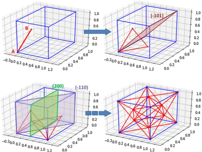
Fig. 3details the building procedure of a FCC structure from two points A and B, by successive application of the isometries of theFm3m
space group. First, a beam produced from the two parent nodes is de-clared. Then, a (110) mirror creates a new node on the bottom face of the cube. Because the distances between the three nodes are equal, this results into a triangle. Then, the application of (101) forms a tetra-hedron, which is the elementary basis of FCC structure, and represents tetrahedral sites of FCC. The (101) mirror propagates it to the other side of the cube, and successive operationsfinally fill the entire space with tetrahedrons, resulting in the well-known FCC octet-truss.
3. Materials and Methods: Finite Elements Model of the lattice structure
3.1. Setting of the 3D geometric design
At this point, the procedure to generate a 3D network of lines is complete. To generate a 3D volumic solid, it is necessary to convert 1D lines into 3D beams. This inflation step is achieved by a stream of Boolean additions of cylinders using the open source software Openscad. Spheres were added at beam intersections to prevent the occurrence of unwanted porosities. Each cylinder was designed to ob-tain at least 12 lines per circles in the section. Each sphere was com-posed of faces with a minimal vertices length of 0.01 mm, in order to provide an accurate model with respect of the 1D model. Finally, the
beams poking out of the elementary representative cube were cut using a Boolean subtraction. Openscad is clearly adapted to generate non-stochastic structures because of its C++ scriptable interface. But it was leading to the occurrence of many design mistakes (for example elon-gated elements) in the output STL file. An additional step using Autodesk Meshmixer was used tofix up the STL file. This procedure removes some duplicate faces,fills some missing faces in the STL, and computes again the triangles of faces to produce a regular surface mesh. All of thesefixing operation were performed to conserve original sur-faces while minimizing the surface mesh distortions. Finally, the vo-lume mesh is generated using Tetgen software, all created elements were using a maximal face area of 0.05 mm and a maximal volume of 1 mm3, it was resulting in a mean number of element per section about
16. These parameters were chosen after a series of tests in order to determine the convergence of the mesh for some topologies. Tetgenfile format was converted in INPfile format by python script. The output files were imported into Abaqus for FEM computing. Postprocessing is conducted using Python and Matlab scripts to plot stiffness as a function of density, and to export the results in 3D maps. The complete numeric string is illustrated onFig. 4. All the different software and scripts were handled by a main script managing the sequence of calculation steps. It allows to run large sets of calculations over wide parameters ranges in an automatic way, with barely no manual operations from the user.
3.2. Finite Elements Model
Finite Elements Model (FEM) was used to evaluate the mechanical behavior of the lattice structures. Thefinite element model is based on linear elasticity, and its setting does not constitute a scientific goal in itself, because the procedure is already very well-known. It is con-sidered only as a convenient tool to determine the stiffness of the structures. The scientific challenge rather lies in the capability to pro-cess a large cluster of structures and to compare them with relevant and systematic post-processing of the FEM data. In particular, significant efforts were dedicated to extract information on the exact contribution of architecture independently of the relative density.
The mechanical loading is compression: it is very common for testing foams and lattices, and it is easy to set up both experimentally and numerically. Compression is applied on a face of the cube, resulting in a macroscopic strain ofε=1%. For this range of low deformation, non-linear behavior was not detected, and buckling did not occur. The opposite face and two perpendicular faces were set as symmetry planes (blue faces onFig. 4). It implies a frictionless sliding on these planes. Therefore, the effective volume tested is 8 times larger than the com-puted volume, and corresponds to a cube with 2 cells width. The re-presentative volume selected is a cube with a size of 1 arbitrary unit length. The model is insensitive to the repetition number of cubic cells if there are at least 8 cells. Due to symmetry planes, this condition is fulfilled and the model is robust with regard to the representative vo-lume. The complete model was computed into the V6.13-2 Abaqus (Dassault Systèmes)finite element calculation software. A general static step has been considered to load lattices. The lattice was meshed with C3D4 linear tetrahedron continuous and isoparametricfinite elements. The average number of elements is within the range 30000-250000 depending on the lattice beam density.
The models were run for three different homogeneous materials, with isotropic elastic properties indicated inTable 1. Three decades of Young modulus are explored to evaluate the sensitivity of the model to the elastic properties of the bulk material. Thefirst material typically has an elastic modulus close to the common ABS polymer used in 3D printers. The second material is typical of thermoset polymers and of some composites or natural materials. Finally, the third material is close to the properties of Ti-6Al–4 V alloy used for additive manufacturing by SLM or EBM. Poisson ratio is set constant at 0.4 for all materials, to capture only the effect of Young modulus on stiffness.
The overall lattice stiffness (noted E) strongly depends on the
Fig. 2. Parametric description of the nodes using a pair of initial atoms, marked with red dots.
relative densityρ and the elastic modulus of the material E0. Therefore,
the relative Young modulus E/E0is used to compare the architectures
with one another. Moreover, the relative densityρ=V/V0is computed,
with V the volume of the lattice, and V0the volume of a bulk
ele-mentary cube. The relative density is a direct measurement of thefilling rate, or the porosity fraction.ρ=1corresponds to a bulk cube, and ρ=0 to an empty cube. The relative modulus E/E0is discussed as a function
ofρ to deduce the elastic performances of lattices.
Six values of radii are explored: r = 0.05, 0.075, 0.1, 0.125, 0.2, 0.3; resulting in six different values of ρ for each lattice structure. In addi-tion, x and y architectural parameters are explored within the range [0; 0.5] with a step of 0.05. The study requires 1188 calculations to entirely cover the 4-dimensions space of (x, y, r, E0) parameters.
4. Results and Discussions
4.1. Resulting lattice architectures
The usual Bravais lattices can be built-up from this new formalism by setting the parameters x and y to bound values. The primitive cube is obtained for x = 0 y = 0, FCC is obtained for x = 0 y = 0.5, and BCC for x = 0.5 y = 0.5. The intermediate structures for some x and y are more interesting and quite unexpected for a couple of them.Fig. 5
Fig. 3. Building a FCC structure from two atoms located at points A (0,0,0) and B (0, 0.5,0.5), by application of the Fm m3 symmetries.
Fig. 4. Numeric string for the mechanical design, computing and post-processing.
Table 1
Elastic properties of materials forfinite elements modeling.
Material Young modulus E0(GPa) Poisson ratio
Material 1–(Polymers) 1 0.4
Material 2– (Reinforced polymers) 10 0.4 Material 3– (Metals) 100 0.4
illustrates the progressive change in structure with growing x and y. If y is increased from 0 to 0.2, then the beams are split in two V-shaped segments (Fig. 5b and e). If x and y vary together with the same value, the beams are not split in two, but get the V-shape, and the structure becomes the hexatruss well-known in literature [26] (Fig. 5c and f). These structures with V-shaped branches are expected to have auxetic properties, with a negative Poisson ratio [27]. A special case occurs for x = 0.25 y = 0.25 (Fig. 5d): in addition to the V-shaped segments, new beams suddenly appear under this condition, because the distance be-tween nodes n°2 (marked in red) is the same as the distance bebe-tween nodes n°1 and 2. These beams are marked by red arrows, and corre-spond to new chemical bonds. The structure gains in density and may have different properties. If the x and y parameters increase together until their bound value set at 0.5, the V-shaped branches of the hexa-truss structure join each other, and it results in a BCC structure.
4.2. Mechanical behavior of the lattices
4.2.1. Relation between density and elastic modulus
The relative lattice Young’s modulus was found to be completely independent from the bulk Young Modulus E0. The E/E0ratio varies
less than 0.01%, while E0varies in the range 1 to 100. The E/E0ratio
can be safely considered as material-independent. Therefore, the con-clusions thereafter can be considered valid for any kind of elastic iso-tropic material for small deformations.
The relative Young’s modulus E/E0is deduced from the set of
cal-culations for different values of (x, y) and with variable density ρ. The overall results are displayed by black dots on Fig. 7. The dots are contained in a narrow area on the plot, and the overall trend is weakly affected by the change in architectures. This means the architecture has a second order effect, behind the density. The trend can be approached by a power law: ⎜ ⎟ = ⎛ ⎝ ⎞ ⎠ E E ρ ρ m 0 0 (2)
This equation properly describes the bounds: if E = E0thenρ = 1. In
addition, parameter m is a much relevant indicator of the elastic be-havior of a structure. In an ideal case, if m=1, then the architecture behavior follows the well-known rule of mixtures: stiffness is linearly correlated with density. According to Ashby et al. [8], if m > 1 then there is a synergy effect: the material gets the best of porosities for mass reduction, and the best of bulk material for stiffness increase. If m < 1, then the result is the“weaker link scenario”, with limited mass reduc-tion and a rapid decrease in stiffness.
Fig. 6illustrates the power law in the specific case of octet-truss
architecture, with x = 0 and y = 0.5. The relation is properly linear, and the slope is the coefficient m. The y offset is set to 0, because the modulus atρ = 1 must match with the bulk Young modulus. The results are in good agreement with the experimental data obtained on octet-truss by Bonatti et al. [28].
The global m coefficient is obtained by a least square regression of the power law. The average value of m isμ = 2.21, and the standard deviation isσ = 0.358. The red line onFig. 7represents the average curve computed with the power law and the mean valueμ. Blue dashed lines correspond to m =μ ± σ. Most cubic architectures have an m factor within this range. The cubic lattice structure benefits more from the weakening due to open porosities than from the reinforcement due to the beams. The trend is clear and the variation is limited despite the wide variety of structures. It can be deduced that this trend is likely to be common for many lattice structures, and only secondary order changes in stiffness are to be expected.Fig. 7also illustrates the relative modulus of two structures with the same density set atρ = 0.5. The x = 0.005 y = 0.1 structure is 68% stiffer than the structure x = 0.25
Fig. 5. Complex lattice structures built up with increasing X and Y architecture parameters.
Fig. 6. Log(E/E0) as a function of Log(ρ) for E0= 1 GPa (blue circles), linearfit (red line),
and comparison with experimental data from Bonatti [28] (pink square dots) for x = 0, y = 0.5 (FCC).
y = 0.4. While the global trend is similar for all the lattices, significant variations of stiffness can result from small changes on m parameter. To conclude, changing the architecture results in noticeable improvement of properties while decreasing density, but it seems difficult to escape from the so-called“weaker link scenario” (m > 1).
The resulting relative modulus E/E0is illustrated on Fig. 8for a
beam radius r = 0.2.
It is to be noticed that for a given radius, the structures with a maximal stiffness are not conventional Bravais lattices (PC, FCC, BCC), but rather correspond to non-trivial combinations of x and y para-meters. The generation of complex cubic structures involves a larger number of beams by unit volume and provides in the end higher me-chanical performances. For instance, the structure x = 0.15 y = 0.35 provides a density twice larger than octet-truss, and an apparent modulus three times larger for r = 0.1. The gathering of architectures
properties into color maps is a powerful tool for the mechanical design of lightweight multifunctional parts.
In the specific case of the research for a lightweight stiff material, the best architecture would be the one having the higher E/E0without
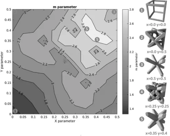
requiring an increase inρ. In terms of m factor, this corresponds to the smaller values.Fig. 9illustrates the variation of m with x and y on a color map. The lowest value possible is reached for the primitive cubic structure, with m = 1.3. This means the primitive structure is the one requiring less matter for a given stiffness in uniaxial compression. This is not very surprising, given that the beams are mostly oriented in the direction of the loading axis, and pure compression is dominant in this structure. On the other hand, octet-truss has a higher m = 1.9, because beams are mostly oriented at 45° from the loading axis, andflexion is predominant. The m value reaches extremely high values for BCC structure, because exactly all the beams are oriented at 54.7° from the loading axis and there are no beams hinderingflexion. The highest value is m = 2.9 for x = 0.35 and y = 0.4: this structure is the one losing its elastic stiffness the most rapidly when ρ drops. One may wonder over the interest for such structures with poor elastic proper-ties. It is actually as interesting as stiff structures. It constitutes the ideal case for the development of low Young modulus biomaterials for bone substitution. The lower the stiffness, the lower the stress-shielding ef-fect, and the higher the bio-integration of an implant made with this structure [29,30]. Therefore, both extremes of m are promising: minimal m is ideal for mass reduction, while maximal m is expected to be ideal for biomaterial applications.
The variations of m are complex and depend on the overall struc-ture, as well as on more local features such as the geometric config-uration of nodes, or the beams length and orientation. Despite this apparent complexity, the global behavior is mostly predominated by beam orientation, and other structural parameters play a second-order effect on stiffness. The orientation of each beam in relation to the loading axis is evaluated by an angleφ as illustrated onFig. 10. If pure compression is applied on the top face of the lattice, the beam will undergo forces including compression andflexion together. The frac-tion of compression in global loading is related to cos(φ). If the value cos(φ) = 1, then the loading in the beams is compression only and the system corresponds to the Voigt upper bound. For lower cos(φ), flexion predominates and m decreases, while the system evolves progressively toward the Reuss lower bound. For each structure, a mean value cos(φ) is calculated over all the beams set. The m factor is linearly correlated to cos(φ), and can be deduced with a reasonable accuracy from the linear Eq.(3):
= −
m 6.02·cos(φ) 0.86 (3)
This equation may be used as afirst approach for an unknown cubic lattice, and would provide a rather correct evaluation of m, and con-sequently of the apparent modulus as a function of beams radius. To conclude, the main factor affecting the m value is the beams orienta-tions. Other architectural factors (e.g. nodes density, beams length) have a second-order effect on m.
4.2.2. Poisson ratio and auxetic structures
The Poisson ratio defines the radial expansion of the matter com-pared to the main loading axis. On a cubic specimen made of lattice structures, the Poisson ratio is the deformation in transverse directions normal to faces, normalized by the compression strain. The transverse deformation is determined by the displacement of outer faces from the central axis of the specimen.
If⎯→⎯uxis the position vector of a mesh node on the outer surface of the cube along the principalεx = dux/uxtransverse direction X, then the expansion due to Poisson ratio is measured by
Therefore, the Poisson ratio is:
= − = − ν ε ε ε du u 1 · x z z x x (4)
Fig. 8. Relative Young modulus E/E0for E0= 1 GPa, as a function of x and y parameters
for r = 0.2.
Fig. 7. Plot of relative Young modulus as a function of relative density for radii between 0.05 and 0.3 (black dots), mean curve for the power law of Eq.(2)(red line), and ex-perimental points from Bonatti 2017 (pink square dots).
For each lattice model, the average Poisson ratio is calculated over all the mesh nodes of outer lateral faces of the cubic specimen. The re-sulting Poisson ratios are summarized on Fig. 11 for r = 0.05. The Poisson ratio varies in a large range from−0.1 to 0.4. Lower values are met for low x and y combinations close to zero, and Poisson decreases until it becomes negative. Such structures with ν < 0 are called “auxetic” [26,31], and have a deformation behavior unmet for common bulk materials. On the other hand, Poisson ratio increases for large x, y values. The maximum is obtained for x > 0.4 and y > 0.4, and ν reaches a value up to 0.4 identical to the property of the bulk material. The Poisson ratio is severely affected by the beams radius. With an increase in lattice density,ν rises progressively, and converges to the
bulk value set toν = 0.4.Fig. 11illustrates the x and y conditions to obtain an auxetic structure withν < 0 (red line). The auxetic area spreads from 0 to 0.2 for x and y values if the radius is as low as 0.05 mm. When the radius increases, this auxetic area vanishes rapidly: for r = 0.075 mm there are only a couple of conditions around x = 0.2 y = 0.05 having auxetic properties. For larger radii, there are no more auxetic structures and the deformation behavior becomes more con-ventional.
The above estimations of Poisson ratio are based upon average displacements of mesh nodes on outer faces. However, one may wonder if the transverse deformation is homogeneous on a lateral face. The answer is no, and it becomes more tedious tofind a proper definition of
Fig. 9. m parameter for the power law E/E0=ρm, and corresponding 3D structures.
Poisson ratio if the transverse deformation fluctuates. Therefore, a second definition, more local, of the Poisson ratio is proposed. The nodes on external faces are defined in cylindrical coordinates, with an angle θ and a radial vector →u. The mesh node undergoes a dis-placement⎯ →du⎯⎯ due to the elastic compression. Only a fraction of this displacement ⎯ →⎯⎯⎯dur contributes to the lateral expansion specific to
Poisson effect. The displacement⎯ →⎯⎯⎯duθcorresponds to the rotation of a
rigid body. The Poisson ratio within the material slice at an angle θ from a principal transverse direction is given byν = dur/u. This value is
calculated as a function of the angleθ, and the plot is illustrated on Fig. 12.
The structure x = 0.05 y = 0.2 is a lattice architecture with a very low Poisson ratio, for a large range of radii, as shown onFig. 12. The local Poisson ratio would be expected to be invariably negative along outer faces. However, it is not the case onFig. 12for r = 0.05. There are large ranges ofθ angles where Poisson is rather close to 0, meaning that beams are neither reentering inside the structure nor moving outside, but stay still at their initial position. For some other ranges ofθ the Poisson ratio drops to values as low as −0.4, meaning that a large number of mesh nodes of outer faces move toward the inner direction.
This is especially the case for angles near 0, 45, and 90°. At 0 and 90°, nodes are located in the middle of V-shaped portions of beams, and the movement to the inside is larger. Forθ = 45°, the edges of the cube are involved. The occurrence of vertical V-shaped beams at this location explains this sudden decrease in Poisson ratio.
As a conclusion, there is much evidence of the auxetic nature of some cubic lattices, but this becomes less accurate at the scale of a beam. The Poisson ratio properly describes macroscopic behavior, but becomes less meaningful at smaller scales. The local Poisson ratio is a useful approach to understand the heterogeneous deformation of outer faces and to visualize the radial deformation of the beam network.
4.2.3. Limitations due to manufacturing techniques
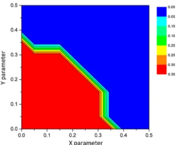
Lattices are very promising for its specific properties, but may turn out to be a challenge to manufacture. Some structures exhibit a high fraction of beams with a low tilt angle φ from the vertical axis. Therefore, in the case of cubic lattices laidflat on the building platform on the {100} plane, some specific issues are expected. It is reported in literature that overhanging structures with a critical angle between the part and the plate above 35° (corresponding toφ < 55°) do not require supports for the SLM process [32]. Fig. 13 illustrates the fraction of beams in cubic lattices having a tilt angleφ > 55°, resulting in some possible printing issues. This map indicates the areas for possible issues due to overhanging. The architecture parameters with possible di ffi-culties is limited to (x + y) < 0.35. For these structures, specific sup-ports may be required, and difficulties or impossibility to remove all of these are expected.
This issue is resolved by tilting the part compared to the building plate [33]. For instance, the Primitive Cubic lattice (x = 0 y = 0) is expected to be difficult to produce according to Fig. 13. When the 〈111〉 direction is oriented parallel to the normal vector of the building plate, all the beams have a tilt angleφ = 55° and supports may become unnecessary.
Additional difficulties may occur with the hexatruss structures. For instance, the point 2 on the structures 2 and 3 ofFig. 5are lower points and it will be disconnected from the rest of the part if the printing is conducted along the {100} planes. For instance, the structure (x = 0 y = 0.2) was printed by Fused Deposition Modeling (FDM), resulting in collapse at this specific location. On the other hand, these collapse
Fig. 11. Poisson ratio as a function of x and y for r = 0.05. The area withν < 0 corresponds to auxetic structures (red line).
Fig. 12. Poisson ratio angular profile for the auxetic structure x = 0.05 y = 0.2 for dif-ferent radius.
effect with SLM technique was significantly reduced, due to the me-chanical support provided by the powder bed. Other structures with such low points were printed successfully by SLM technique [34].
Manufacture can result in some other difficulties, like beam radius deviation [35]. This phenomenon can be considered in the present work by correcting the input parameter depending on the orientation of each beam.
4.2.4. Applications to mechanical design
As mentioned previously (Table 1), three values of Young Modulus were tested over three orders of magnitude, and the results were found to be identical in the three cases. Using the color maps, it is possible to estimate m factor and E/E0. The data set of calculated E module is
il-lustrated onFig. 14over an Ashby map, for ABS with E0= 1 GPa, and
for TA6 V titanium alloy with E0= 100 GPa. As a result, one can predict
any apparent Young modulus for any material and then give new upper
and lower bond (red dashed line inFig. 14). These bonds gave us an Ashby map which takes into account bulky materials and associated cubic lattices structures.
In the case of polymer-based cubic lattices, the apparent modulus of the structures varies between 1 MPa and 1 GPa. For densities as low as ρ < 102kg m−3, the elastic properties are very similar to polymer
foams. It may meet specific applications for thermal and acoustic in-sulation, or vibrations damping applications, or for structuralflexible parts. With metallic lattices made of TA6V, the modulus also decreases with density. The metallic lattice has properties similar to composites, then polymers, then natural materials as density gradually decreases. One may wonder why choosing an expensive metallic lattice while polymers constitute such a cheap and efficient option. Choosing a metallic lattice can be attractive due to higher creep properties com-pared with a bulk polymer. The electric and thermal conductivity, friction resistance, physical properties and biocompatibility are some examples of additional functions available with metallic TA6V lattice, which would be difficult to obtain with commercial polymers. Therefore, lattice architecture materials show the best of their potential for applications combining mechanical design with other physical properties within a multifunction
5. Conclusion
Lattices with a cubic symmetry were investigated usingfinite ele-ments modeling. A new parameterization technique based on crystal-lography using them3m point group was proposed. This technique requires only two parameters, corresponding to the position of initial atoms, and provides a large panel of different structures.
– The lattice can build up on its own due to symmetries, and its generation is completely automated by scripts. This procedure does not require the use of close-loop algorithms, contrary to topological optimization. It is straightforward and more versatile for mechanical engineering, as it does not depend on the geometry of the parts considered. This procedure also gives us the possibility to make architecturally graded materials.
– The global trend for modulus variation with density is a power law, with an exponent m representative of the elastic behavior. The m factor is independent from beams sections and from material, and properly illustrates the contribution of architecture to the apparent lattice modulus. In addition, the Poisson ratio was determined for all the structures, and was shown to vary widely, from its bulk value down to negative values for some specific auxetic architectures. – The elastic behavior was simulated and summarized on color maps.
These abacuses are powerful tools for mechanical design, and pro-vide predictions of the resulting modulus at a glance. The con-tinuous generation of a large panel of cubic lattices allows for the selection of optimal structures to reach a target stiffness value, without necessarily affecting the density.
– It makes it possible to adjust within a suitable range the Young modulus while preserving a minimal density. However, the severe dependence of stiffness on density, and the limited variation of specific Young modulus are two main limitations to this method. Some stiffness ranges remain beyond reach with cubic lattices, and it would be necessary to modify either the density or the bulk material properties to achieve it.
This paper is dedicated to the generation of lattices, and the methodology was extensively detailed. In the future work, an experi-mental procedure will be established to confirm the material in-dependence of effective elastic properties. In addition, the use of dif-ferent additive manufacturing processes will provide information on process-dependence.
Fig. 13. Fraction of beams with a tilt angleφ > 55° where the use of supports may become necessary.
Fig. 14. Lattices structures (black dots) cover a large range of Young modulus and density on an Ashby map (red area), and diverge from the common bulk polymers (blue area) toward the area corresponding to foams (green area).
Acknowledgments
The authors acknowledge the financial support from French National Research Agency ANR (LabEx DAMAS, Grant no.ANR-11-LABX-0008-01).
References
[1] J. Martinez, J. Dumas, S. Lefebvre, Procedural voronoi foams for additive manu-facturing, ACM Transactions on Graphics 35 (2016) 44.
[2] J. Martinez, H. Song, J. Dumas, S. Lefebvre, Orthotropic k-nearest foams for ad-ditive manufacturing, ACM Transactions on Graphics 36 (2017) 121.
[3] H. Eschenauer, N. Olhoff, Topology optimization of continuum structures: A review, Appl. Mech. Rev 54 (4) (2001) 331–390.
[4] M. Wang, X. Wang, D. Guo, A level set method for structural topology optimization, Comput. Methods Appl. Mech Engrg. (no. 192) (2003) 227–246.
[5] M.K. Thompson, Design for Additive Manufacturing: Trends, opportunities, con-siderations and constraints, Manufacturing Technology (no. 65) (2016) 737–760. [6] X. Wang, S. Xu, S. Zhou, W. Xu, M. Leary, P. Choong, M. Quian, M. Brandt, Y. Xie,
Toplogical design and additive manufacturing of porous metals for bone scaffolds and orthopaedic implants: a review, Biomaterials (no. 83) (2016) 127–141. [7] A. Öschner, H. Altenbach, L. Martins da Silva, Fabrication and Charaterization in
the Micro-Nano Range, Berlin: Advanced Structured Materials (2011). [8] M. Ashby, Y. Bréchet, Designing hybrid materials, Acta Materialia 51 (2003)
5801–5821.
[9] A. Salimon, Y. Bréchet, M.F. Ashby, A.L. Greer, Potential applications for steel and titanium metal foams, Journal of Materials Science 40 (2005) 5793–5799. [10] A. Aremu, I. Maskery, C. Tuck, I. Ashcroft, R. Wildman, R. Hague, A Comparative
Finite Element Study of Cubic Unit Cells for Selective Laser Melting, Solid Freeform Fabrication Symposium (2014).
[11] X. Zheng, Ultralight, Ultrastiff Mechanical Metamaterials, Science 344 (6190) (2014) 1373–1377.
[12] R. B. Fuller, Synergetic Building Construction, Patent US 2986241A, 7 Feb (1961). [13] A. Nayfeh, M. Hefzy, Continuum Modeling of Three-Dimensional Truss-like Space
Structures, AIAA Journal 16 (1978) 779–787.
[14] V. Deshpande, N. Fleck, M. Ashby, Effective properties of the octet-truss lattice material, Journal of the Mechanics and Physics of Solids 49 (2001) 1747–1769. [15] V.S. Deshpande, M.F. Ashby, N.A. Fleck, Foam topology bending versus stretching
dominated architectures, Acta materalia 49 (2001) 1035–1040.
[16] L. Dong, V. Deshpande, H. Wadley, Mechanical response of Ti–6Al–4V octet-truss lattice structures, International Journal of Solids and Structures 60-61 (2015) 107–124.
[17] J.C. Maxwell, On the calculation of the equilibrium and stiffness of frames, Philosophical Magazine 27 (1864) 294.
[18] D.M. Watts, Exploiting the design freedom of RM, Proceedings of the 17th SFF
Symposium (2006).
[19] Y. Huang, Y. Xue, X. Wang, F. Han, Mechanical behavior of three-dimensional pyramidal aluminum lattice materials, Materials Science & Engineering A 696 (2017) 520–528.
[20] L. Xiao, W. Song, C. Wang, H. Liu, H. Tang, J. Wang, Mechanical behavior of open-cell rhombic dodecahedron Ti–6Al–4V lattice structure, Materials Science & Engineering A 640 (2015) 375–384.
[21] T. Bückmann, On three-dimensional dilational elastic metamaterials, New journal of physics 16 (2014).
[22] S. Hengsbach, Direct laser writing of auxetic structures: present capabilities and challenges, Smart Materials and Structures 23 (no. 8) (2014).
[23] J. Schwerdtfeger, Design of Auxetic Structures via Mathematical Optimization, Advanced Materials 23 (2011) 2650–2654.
[24] W. Jiang, L. Shaohua, Y. Luo, S. Xu, J. Gong, S. Tu, An analytical model to predict the equivalent creep strain rate of a lattice truss panel structure, Materials Science & Engineering A 661 (2016) 152–159.
[25] N. Yamada, K. Maruya, Y. Yamaguchi, X. Cao, Y. Ninomiya, p- to n-Type Conversion and Nonmetal–Metal Transition of Lithium-Inserted Cu3N Films, Chemistry of Materials 27 (2015) 8076–8083.
[26] J. Dirrenberger, S. Forest, D. Jeulin, Effective elastic properties of auxetic micro-structures: anisotropy and structural applications, International Journal of Mechanics and Materials in Design 9 (2013) 21–33.
[27] K. Evans, M. Nkansah, I. Hutchinson, S. Rogers, Molecular network design, Nature 353 (1991) 124–125.
[28] C. Bonatti, D. Mohr, Large Deformation Response of Additively-Manufactured FCC Metamaterials: From Octet Truss Lattices Towards Continuous Shell
Mesostructures, International Journal of Plasticity (2017),http://dx.doi.org/10. 1016/j.ijplas.2017.02.003.
[29] A. Barbas, Etude biomécanique de substituts osseux en titane poreux destinés à la chriurgie maxillo-faciale Phd Thesis, (2011).
[30] B. Piotrowski, A. Baptista, E. Patoor, P. Bravetti, A. Eberhardt, P. Laheurte, Interaction of bone-dental implant with new ultra low modulus alloy using a nu-merical approach, Materials Science and Engineering C 38 (2014) 151–160. [31] J. Dirrenberger, S. Forest, D. Jeulin, C. Colin, Homogenization of periodic auxetic
materials, Engineering Procedia 10 (2011) 1847–1852.
[32] M. Cloots, B.A. Spierings, K. Wegener, Assessing new support minimizing strategies for the additive manufacturing technology SLM, International Solid Freeform Fabrication Proceedings (2013) 631–643.
[33] P. Alexander, S. Allen, D. Dutta, Part orientation and build cost determination in layered manufacturing, Computer-Aided Design 30 (1998) 343–358.
[34] O. Al-Ketan, R. Rowshan, R.K.A. Al-Rub, Topology-mechanical property relation-ship of 3D printed strut, skeletal, and sheet based periodic metallic cellular mate-rials, Additive Manufacturing 19 (2018) 167–183.
[35] M. Suard, G. Martin, P. Lhuissier, R. Dendievel, F. Vignat, J.J. Blandin, F. Villeneuve, Mechanical equivalent diameter of single struts for the stiffness prediction of lattice structures produced by Electron Beam Melting, Additive Manufacturing 8 (2015) 124–131.