Science Arts & Métiers (SAM)
is an open access repository that collects the work of Arts et Métiers Institute of
Technology researchers and makes it freely available over the web where possible.
This is an author-deposited version published in: https://sam.ensam.eu Handle ID: .http://hdl.handle.net/10985/14955
To cite this version :
Rabiae ARIF, Guillaume FROMENTIN, Frédéric ROSSI, Bertrand MARCON, Patrick
BLANDENET - Mechanical study in drilling of heat resistant austenitic stainless steel - In: 8th CIRP Conference on High Performance Cutting (HPC 2018), Hongrie, 2018-06-25 - Procedia CIRP - 2018
Any correspondence concerning this service should be sent to the repository Administrator : archiveouverte@ensam.eu
Available online at www.sciencedirect.com
ScienceDirect
Procedia CIRP 00 (2018) 000–000 www.elsevier.com/locate/procedia2212-8271 © 2018 The Authors. Published by Elsevier Ltd. This is an open access article under the CC BY-NC-ND license (http://creativecommons.org/licenses/by-nc-nd/3.0/)
Peer-review under responsibility of the International Scientific Committee of the 8th CIRP Conference on High Performance Cutting (HPC 2018)..
8
thCIRP Conference on High Performance Cutting (HPC 2018)
Mechanical study in drilling of heat resistant austenitic stainless steel
Rabiae Arif
a,b*, Guillaume Fromentin
a, Frédéric Rossi
a, Bertrand Marcon
a, Patrick Blandenet
baArts et Metiers ParisTech, LaBoMaP, Rue Porte de Paris, Cluny, 71250 France bSaint Jean Tooling, 309 Rue le sou, Saint Jean d’Ardières, 69220, France
* Corresponding author. Tel.: +33 3 85 59 53 88; fax: +33 3 85 59 53 70. E-mail address: rabiae.arif@ensam.eu
Abstract
Machining of difficult-to-cut-materials like heat resistant stainless steels leads to the rapid tool wear and tool failure. The analysis of drilling process of these steels is even more difficult as it is not easy to investigate the cutting process at the drill tip. Therefore for this critical operation, modelling of cutting forces is very important. The study of the mechanical loading is based on the cutting tool geometry variation along the cutting edge. This study aims to investigate the drilling of heat resistant stainless steels with two geometries of twist drills, by analyzing specific cutting energy and forces at a global and a local scale.
© 2018 The Authors. Published by Elsevier Ltd. This is an open access article under the CC BY-NC-ND license (http://creativecommons.org/licenses/by-nc-nd/3.0/)
Peer-review under responsibility of the International Scientific Committee of the 8th CIRP Conference on High Performance Cutting (HPC 2018).
Keywords: Stainless steel, Drilling, Specific cutting force, Tool geometry
1. Introduction
In automotive application, turbocharger housings made of heat resistant austenitic stainless steel (HRASS) are more and more used. These steels are widely used because of their thermo-mechanical properties at high temperature, mainly low conductivity, and high ductility. Investigations about HRASS machining under different cutting processes had been initiated by industries from whom improvement of productivity is a major economic issue[1]. However, improvements have been hindered by many problems, such as rapid tool wear and tool failure. The industrial partner of the present research aims to qualify and control HRASS machining especially in drilling process. To understand the machinability of these peculiar steels, it is important to analyze the cutting forces generated and their strong dependency to the cutting conditions. Even more in drilling where cutting conditions are changing along the cutting edge which makes the analysis more complicated.
In literature, several works focus on the cutting parameters effect in drilling of stainless steel to improve the tool life. Sultan et al [2] investigate the effect of the cutting speed and the feed rate on the tool life and hole quality. They conclude
that the flank wear decreases rapidly when the cutting speed and feed rate are decreasing. However, the surface roughness decreases when the cutting speed increases. Indeed, the cutting speed reduction generates Built-up Edge (BUE) formation which affects the machined surface. In the same manner, Lin [3] concludes that the tool life increases as the feed rate and the cutting speed decreases. Those analysis are completed by Vas et Fernandes [4] who relate the tool life to the tool geometry and temperature at tool/chip interface. They conclude that the temperature increases with the feed rate and cutting speed; as direct consequence, the tool wears quickly. Those pre-cited research works are mainly experimental; on the other hand cutting forces modelization is another fruitful way to enhance the drilling process comprehension. Koehler [5] studies the effect of the main cutting edge form on the forces distribution. Hence, it is well known that the main cutting edge shape influences significantly the material flow, the forces, and the temperatures [5]. In the same way, Claudin et al [6] analyze the effect of the drill geometry on forces during the drill tip penetration; they determine the influence of each drill zones on the total thrust during machining.
2 Rabiae ARIF/ Procedia CIRP 00 (2018) 000–000
The aim of this study is to enhance the comprehension of HRASS cutting by comparing two cutting geometries of twist drills using a global and a local analysis by material-tool pair and edge material pair approaches respectively [7].
2. Experimental set-up 2.1. Acquisition device
Drilling experiments have been performed on a DMC 65V CNC 3-axis machining center with a spindle of 25 kW rotating at 18000 tr/min and Siemens Numerical Controller. During experiments, three NC analog outputs are used to record: the feed rate Vf, the spindle speed N, and the tool position z. In addition, cutting forces are monitored by a Rotating Cutting force Dynamometer (RCD) Kistler 9123C3 with a charger amplifier. RCD is used for dynamic and quasi-static measurements of the axial force (Ff = Fz) and the torque (Mc = Mz).
2.2. Work-material
The material machined is a high alloyed austenitic cast steel, which identification number is 1.4837; according to DIN EN 10295 it is referred as GX 40CrNiNbSi 24-12. This austenitic cast steel is typically used for turbo charger housings. It contains 24% of chromium and 12% of nickel with slight traces of silicon and niobium which create hard carbides affecting the material machinability.
2.3. Cutting tools
This research work studies the effect of two WC-Co twist drills with a 5.1 mm diameter. The first one has 2 teeth (Z2), the second has 3 teeth (Z3) with different cutting geometry, i.e. chisel, web thinning, and cutting edge are different. The drills were digitalized using Alicona microscope to get a 3D
model of the real tool shapes. Then the effective rake angle γn
is determined in the normal plan Pn, as mentioned in the section 4.1.
3. Approaches adopted in drilling analysis
The present study focuses on the characterization of the
two drills presented under the same cutting conditions.
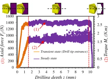
Drilling forces evolution contains mainly two steps, cf. Fig. 1, corresponding respectively to the drill tip penetration and the complete hole drilling once the drill tip is fully engaged. This subdivision leads to two following main approaches to analyze the drilling behavior:
The global analysis based on specific cutting energies Kc,f and Kc,c, is conducted during the steady state. Thus, this approach includes the cut effect and the margin friction as well,
The local analysis during tool tip penetration focuses only on the evolution of forces along cutting edges in relation with the local cutting geometry.
Fig. 1. Axial force (Ff) and torque (Mc) taking place during drilling with the
Z3 WC-Co drill, f = 0.025 mm/rev, and Vc = 30 m/min – Definition of
transient state and steady state domains
4. Results and discussion
4.1. Global analysis of specific cutting energies
In industrial context, it is important to define the optimal cutting conditions which minimize the specific cutting energies needed to cut the material; this kind of analysis is usually named Tool-Material Pair methodology [9]. Furthermore, this approach is used to compare the efficiency of the two twist drills.
In drilling, mechanical actions are decomposed into two main forces: the feed force (Ff) in the axial drill direction and
the tangential one acting on the cutting edge (Fc) that induces
the cutting torque (Mc). Based on their mean value during the
steady state, two specific cutting forces respectively noted Kc,f
and Kc,c are defined and calculated using the Eq. (1) according
to the corresponding standard [9].
, , 2 2 8000 z c f c c c F K D f M K D f (1)
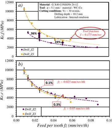
The Fig. 2 presents the results varying the feed rate for the two considered drills (Z2 and Z3). It shows the evolution of
Kc,f and Kc,c at the cutting speed Vc = 30 m/min and the feed rates from 0.025 mm/rev to 0.175 mm/rev. In order to ease the comparison of both drills, the graph is plotted in feed rate per tooth (rather than in feed rate per revolution.) to consider the same cut thickness in each cases.
The results demonstrate a large decrease of specific cutting energies, especially of Kc,f, when the feed increases, i.e. for higher cut thickness. That is a usual fundamental observation is metal cutting.
Secondly, it is showed that Kc,f of Z3 drill is higher than the Z2 drill one. As the feed increases, the gap between the two curves decreases. Moreover, the difference between the two trends could reach 36%, when the feed rate equals
0.025 mm/rev/th, and 24% when fz = 0.05 mm/rev/th. Despite
of the significant difference on Kc,f, , it appears that Kc,c.is slightly the same between both drills, the torque being much
0 0.5 1 1.5 2 2.5 3 0 200 400 600 800 1000 1200 1400 1600 0 1 2 3 4 5 6 7 8 9 10
T
or
qu
e
M
c(N.m)
Axial f
or
ce
F
f(N)
Drilling depth z (mm)Transient state (Drill tip entrance) Steady state (1) (2) (1 ) (2 )
less sensitive to the cutting geometry than to the penetration force.
One can also observe that using a feed rate of 0.175 mm/rev led to the Z3 drill rupture while the Z2 drill resists for rather more severe conditions. From this analysis, it appears that the specific energy brought by the Z3 drill to form the chip is higher than the Z2 drill. The reason of the Z3 tool fracture is resulting from the mechanical load and from a reduced strength of the tool as well.
The mechanical load is higher due to an additional tooth compared to a Z2 drill. Furthermore, the mechanical load is also affected by a different cutting geometry of the Z3 drill.
Indeed, chisel edge is widely different between the two drills; being 3 times larger for the Z3 drill. Actually, the chisel edge is the first to get contact with the material and has a very
negative cutting geometry (γn around -60°) as shown in Fig. 4,
which tends to make the drill ploughing in the material rather than forming the chip [8], and consequently creates much higher pressure on the cutting edge.
More elements will be provided to support that statement in the following section.
Fig. 2. (a): Specific cutting force in the feed direction, (b): Specific cutting force in the cutting direction.
4.2. Local analysis of mechanical forces
This section focuses on cutting forces at a local scale to describe accurately phenomenon occurring at the chisel edge and the cutting edge progressively during the drill tip penetration (cf. transient state Fig. 1). This analysis is carried out for each drill based on the instantaneous axial force and
torque. The approach uses the edge discretization
methodology to establish the contribution of each elementary cutting edge on the global cutting forces [6].
The Fig. 3 presents the principle of the calculation of each elementary cutting edge contribution. During the drill tip
penetration, the cutting edge engagement increases
progressively, from the drill axis to the drill corner. Therefore, global forces evolve as a function of the radius (R) of the last engaged point of the cutting edge linked to the z tool position. Consequently, the local force Flfi and Flci on the ith cutting edge element is calculated as define by Eq. (2).
Fig. 3. Principle of the cutting edge discretization during drill tip penetration.
1 1 1 l i i fi e l i i ci i e Ff Ff F Z L Mc Mc F R Z L tan( ) cos( ) i i i i r i e r R z dz L (2)
The Fig. 4 shows the axial force and the cutting forces applied on each elementary cutting edge of each drill with the
same cutting conditions (Vc = 30 m/min, fz = 0.025 mm/rev/th)
to highlight the difference of behavior between Z2 drill and Z3 drill during the transient state.
Fig. 4. Linear feed force and cutting force respectively Ffl, Fcl correlation with
the rake angle γn taken in normal plan.(Pn)
The ratio between the cut thickness h and the cutting edge radius rβ should be largely higher than 1 to see the effect of the rake angle. In our case, this ratio is equal to 1.8 for both drills, due to the small feed chosen for this analysis.
0 2000 4000 6000 8000 10000 12000 Kc,f ( MPa) Drill_Z2 Drill_Z3 Material : G X40 CrNiSiNb 24-12 Tool : ϕ = 5.1 mm / material : WC-Co Cutting conditions: Vc = 30 m/min,
Drilling depth = 10.2 mm Lubrication : Internal emulsion
36% 24% Tool fracture f = 0.175 mm/rev 0 2000 4000 6000 8000 10000 12000 0.00 0.02 0.04 0.06 0.08 0.10 Kc,c ( MP a)
Feed per tooth fz (mm/rev/th) Drill_Z2 Drill_Z3 0.1% 0.3% fz = 0.025 mm/rev/tth fz = 0.05 mm/rev/tth
a)
b)
Mc dzi Z Le dz R i i+1 Le Ri Fzi Mci Fzi+1 Mci+1 X κri Ff Ffi Mci Ffi+1 Mci+1 Mci4 Rabiae ARIF/ Procedia CIRP 00 (2018) 000–000
Fig. 4 shows that the local forces are correlated with the rake angle γn measured in the normal plan (Pn). The results display that for the two drills, the Ffl and Fcl are much higher at the drills center. Indeed, as mentioned before, the chisel edge rake angle is highly negative which leads to high local forces in drill center. Besides, in the chisel edge center, the cutting edge is almost absent. R
At the central edge of Z3 drill, it has been observed that elementary cutting edge generate higher axial forces Fzl than those of Z2 drill. However, they generate low cutting force due to the negative rake angle in the central edge. Reciprocally, when the rake angle becomes positive, the axial forces are decreasing.
4.3. Effect of cutting conditions on local specific cutting forces
Specific cutting forces Klc,f and Klc,c can be computed as define by Eq. (3) from the local linear cutting forces Ffl and Fcl. Thus, this study is focused on the local specific cutting forces along the cutting edge, and don’t consider the margin effect.
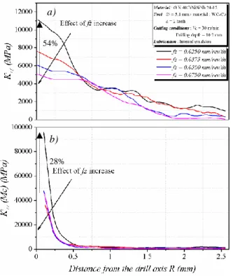
Fig. 5 shows the effect of the feed rate on local specific cutting forces Klc,f and Klc,c evolution along the cutting edge for Z2 drill. From these results, it appears that both of Klc,f and Klc,c are pretty independent of the feed rate in the part close to the cutting tip. In the chisel edge zone, the gap of Klc,f and Klc,c
(from fz = 0.025 to 0.075 mm/rev/th) could respectively reach
54% and 28%.
Fig. 5. (a) Specific cutting forces distribution in the feed direction Kl c,f , and
(b) the cutting direction Klc,c (b).
This high difference can be explained by the negative rake angle (close to -65°) of the chisel edge which ploughs, as mentioned before. , , sin( ) sin( ) i i i i i i l f l c f z r l c l c c z r F K f F K f (3)
Moreover stainless steel material is known to be sensitive to work-hardening [11]. Thereby, the plasticization of the workpiece material is increased with low feed rate and consequently rises up the specific forces.
5. Conclusion
The aim of this research work is to enhance heat resistant austenitic stainless steel (HRASS) machinability especially in drilling process by analyzing the cutting forces with combined global and local approaches. On one hand the global analysis shows that the Z3 drill generates higher cutting pressure compared to the Z2 drill. These global results are completed by the local analysis which correlates the axial force and the cutting force with the rake angle based on cutting edge discretization. It appears that elementary cutting edges of Z3 drill have a strong negative rake angle at the central cutting edge which generates a high axial force and low cutting force compared to Z2 drill. In addition, local specific cutting forces could be calculated in drilling process based on local forces along the cutting edge. Consequently, both approaches (global and local) give the same trend of specific cutting pressure according to cutting conditions (feed rate). Further investigations will deal with the work-hardening of the workpiece material using special Quick Stop Test device during the drilling operation.
6. References
[1] Roland H, Panosso ZR, Göran E, and Oliver C. Threading in heat resistant cast stainless steel din 1.4848 for turbocharger housings. Vestnik MGSU, Proceedings of Moscow State University of Civil Engineering 2013; 2: 93-100.
[2] Sultan AZ, Sharif S, and Kurniawan D. Effect of machining parameters on tool wear and hole quality of AISI 316L stainless steel in conventional drilling. Procedia Manuf; 2015; 2: 202-207.
[3] Lin TR. Cutting behaviour using variable feed and variable speed when drilling stainless steel with TiN-coated carbide drills. Int J Adv Manuf Technol 2002; 19(9): 629-636.
[4] Vas JS, Fernandes A, D'Souza A, Rai A, and Quadros JD. Analysis of temperature changes during dry drilling of austenitic stainless steels on twist drills having different point angles. J Mech Eng Autom 2016; 6(5A): 121-125.
[5] Koehler W. Analysis of the high performance drilling process: influence of shape and profile of the cutting edge of twist drills. J Manuf Sci Eng 2008; 130(5): 51001-1-51001-7
[6] Claudin C, Poulachon G, and Lambertin M. Correlation between drill geometry and mechanical forces in MQL conditions. Mach Sci Technol 2008; 12(1): 133-144.
[7] Campocasso S, Costes JP, Fromentin G, Bissey-Breton S, and Poulachon G. A generalised geometrical model of turning operations for cutting force modelling using edge discretisation. Appl Math Model 2015; 39(21): 6612-6630.
[8] Bonnet C. Understanding of cutting mechanisms in drilling of the Ti6Al4V / carbon fiber composite stack. MSc report, Arts et Métiers ParisTech, Cluny, France; 2010 (in French).
[9] NF E66-520-8, 2000, standard.
[10] Tanguy JC. Drilling with a twist drill (Perçage au foret hélicoïdal). Centre techniques des industries mécaniques Eds 1993: pp. 139 (in French).
[11] Dolinšek S. Work-hardening in the drilling of austenitic stainless steels. J Mater Process 2003; 133(1-2): 63-70.
54%
28%
a)