AN ATTEMPT TO CREATE POWER LINE ANTI-GALLOPING DEVICE WITH HYSTERETIC TYPE ENERGY DISSIPATION
Alexandre VINOGRADOV*, Irina PLATONOVA*, Andrei AKKURATOV* and Jean-Louis LILIEN**
*ESSP J-S Cy – Vysokovoltnyi Lane, 1, build. 36 127566 Moscow, Russia [email protected]
**Montefiore Institute of Electricity – University of Liege TDEE, B28 Sart Tilman B–4000 Liege, Belgium [email protected]
Abstract
This paper sets forth a new concept of the anti-galloping device known as TDD. A kind of hysteretic-type damper is put into a new TDD model; this has made the structure more compacted and attractive for practical applications. The damper is based on energy dissipation due to elastomer inserts rolling with friction along their track ways. Parameters of the new damper are revealed: energy dissipation and the stiffness values are dependent on angle of displacement. Transfer function of the TDD device equipped with the new damper has been defined in tests and calculated theoretically.
Introduction
The first and quite a successful attempt to use a damped pendulum concept for protection Power Transmission Lines with bundled conductors against galloping was made some 15 years ago [1]. This design acquired the name TDD (Torsional Damper and Detuner). An initial design was based on the use of dampers made of viscous rubber. Its efficiency against galloping has been reliably proved by field experiments [2,3]. But this device in its original form turned out rather bulky and expensive.
To improve consumer properties of the TDD device, we have put forward a compacted hysteretic-type damping system instead of massive
rubber members. Rather small elastomer inserts rolling on their tracks were introduced into this damper as the main dissipative element. Mechanical energy was adsorbed here due to both internal friction in elastomer inserts and inter-face friction at elastomer-metal contacts. In Fig. 1, a simple qualitative experi-ment aimed to demonstrate capability of a damper of this type is reproduced.
Logari-Fig. 1. High-damped movement of a pendulum 10 kg·m2
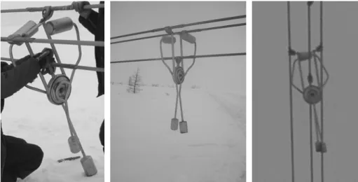
Fig. 2. Installation of the TDD antigalloping device on a Transmission Line: a) mounting on a bundle; b) the bundle before raising; c) the TDD is at a span of T/L
thmic decrement values of oscillation were typically at a level of 1.5-2.5, and this became an encouraging reason to dwell into further development of the TDD device equipped with a damper of the type proposed. By now, a conceptual design of the TDD for three-conductor bundles is completed in development and laboratory testing, and is undergone field trials (Fig. 2).
Tests to define parameters of the damping unit
A set of models has been developed and probed, to adapt the damper to the TDD concept. Taking into account an average weight of TDD as 25…35 kg, the damping unit with the pendulum was tuned to a frequency approximately 0.4 – 0.6 Hz. A version of the damper was installed on a frame (Fig. 3) that reproduced bundled conductors (A, B, C). The frame was given sinusoidal swinging of constant amplitude and frequency with an angle
γ
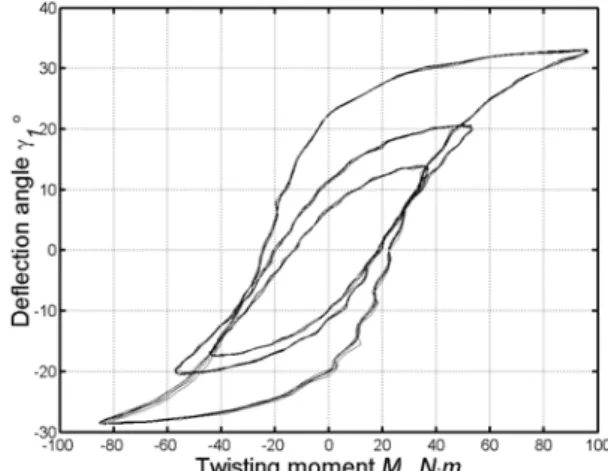
1 from a driving mechanism (not shown). The pendulum (weights P1, P2) was fixed through load cell (L.C.), and this provided loading of the damper (with its spring-type part S and the dissipative part D). In a series of subsequent experiments, a hysteretic loop of the damping unit was investigated in detail (period of oscillations mostly was in the range of 0.2-0.8 Hz). And it was found that the system had low sensitivity to oscillation frequency changes – on the hysteretic curves reproduced in Fig. 4, the recordings for 0.2; 0.5; 0.8 Hz practically overlapped one another.This might be expected to a hysteretic-type damper, if viscous friction in elastomer is small comparatively with friction on the surfaces. As for a dependence of energy dissipated versus deflection angle values, it is well pronounced (see Fig. 5) and is increasing practically in proportion to the angle growth. One can see that
1 O A B C P P 2 1 S D L.C.
Fig. 3 Testing of the TDD damper: the hysteretic loop definition arrangement
Fig. 4. Hysteretic loops measured for the range of
frequencies 0.2 – 0.8 Hz Fig. 5. Hysteretic loops measured for the range of deflection angles. Frequency 0.2 Hz
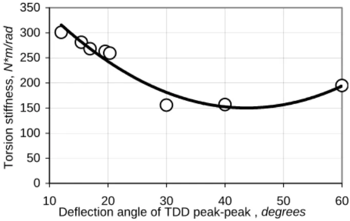
energy dissipated reaches as high as tens of joules per oscillation cycle at amplitudes closer to maximum ones. Figure 6 summarizes more distinctly the data obtained in these experiments. A feature of the damper under consideration is variation of its stiffness depending on displacement am- plitudes [4]: at smaller deflection angles, its averaged stiffness is noticeably higher than at greater ones (Fig. 7). Besides pendulum parameters variation, we got an effective way to tune the TDD device to eigenfrequencies of a T/L span with changing a number of elastomer inserts in the damping unit,
whereas a value of the inserts deformation (i.e. contact pressure) gave some (small) influence on the TDD damping parameters. 0 10 20 30 40 50 60 20 30 40 50 60 70
Deflection amplitude (peak-peak), degrees
E nergy di s s ipat e d , J Frequency 0.2 Hz Frequency 0.5 Hz Frequency 0.8 Hz 0 50 100 150 200 250 300 350 10 20 30 40 50 60
Deflection angle of TDD peak-peak , degrees
Torsion st
if
fness,
N*m/rad
Fig. 6. Energy dissipated per oscillation cycle versus pendulum deflection angle
Fig. 7. Torsional stiffness variation of the damper versus deflection angle
TDD transfer function calculation
Full mathematical description of the TDD device when it is installed onto a span of a Transmission Line and is drawn into torsional and transversal oscillations of the bundle experiencing galloping, is fully described with the help of four dynamic Equations. In our case, these Equations have been derived via d’Alembert Principle, with the results similar to those given in [5,6]. For our purposes, the Equation of torsional displacements of the TDD pendulum is of importance only (see also Fig. 8):
(
)
(
)
2 2 2 2 cos 2 sin p b b p p p b p b p b d d d I m l l dt dt dt θ + ⎛ θ θ− θ + θ θ− ⎛ θ ⎞ ⎞= ⎜ ⎜ ⎟ ⎟ ⎜ ⎝ ⎠ ⎟ ⎝ ⎠(
p b) ( )
sin p b p p d f c P l dt θ θ p θ θ θ − − − − − (1)Wherein: Ip – inertia moment of the system «damping unit + pendulum and weights» relatively its axis, kg⋅m2; θ p – rotation angle of this system, rad; θ b – rotation angle of the TDD body, rad; lb – a distance between the bundle axis and damping axis, m; lp – a distance between damping unit axis and the centermass of pendulum and weights, m; Pp and mp – weight and mass of this system, N and kg, respectively; с – spring torsional stiffness of the pendulum, N⋅m/rad; f – viscous torsional stiffness of the pendulum, N⋅m⋅s/rad.
Estimation of the viscous and spring stiffnesses needed to get transfer Function calculated values, has been made on the basis of hysteretic loops measurements. The following expression was used to define viscous stiffness equivalent to dissipative capacity of the damping unit found in measurements:
(
)
2 max p b W f πω θ θ ∆ = − (2)wherein: ∆W – energy dissipated per one cycle (as defined from a hysteretic loop area), J; ω – oscillation frequency, rad/s; (θ p - θ b) max – maximum value of angular displacement between bundle and pendulum (see Fig. 8), rad. To estimate spring stiffness equivalent to that observed in the tests, we used a load-on diagram branch of the hysteretic loop [4]. These values are in the range of the
lowest figures given in Fig. 7, as far as all the evaluations have been made for angular displacements between 10 and 15 degrees. The scheme of this experiment corresponded to that depicted in Fig. 8.
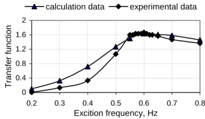
Results of transfer Function calculations are compared to those obtained in experiments in Figs. 9 and 10. Since increase of spring stiffness at low amplitudes was not taken into account here, transfer Function calculated values at low frequency go higher than those in experiments.
Conclusion
1. A new damping device effective against Power Line galloping and based on new ideas, has been designed.
2. This device is known as “TDD” and is working on the principles of oscillations detuning and damping. Its main idea is to avoid energy transfer from the wind to vertical movement.
3. One of the biggest challenges needed to get over, was to create a rather light system covering galloping range of frequencies with sufficient damping.
4. We succeed to build a damper with some tens joules dissipation per device in the range 0.2 to 1 Hz (i.e. appr. 5 – 20 watt system) with appropriate resonance. Internal design parameters (number of balls, tightening torque) have been investigated to reach targeted values. Y Z O A B C l p b l Pp f c op ob O'
Fig. 8. Schematic diagram of the TDD installed onto conductors
5. The TDD designed anew is actually under testing on the field as well as on full scale test span.
\ 0 0.4 0.8 1.2 1.6 2 0.2 0.3 0.4 0.5 0.6 0.7 0.8 Excitation frequency, Hz T ransfer function
experimental data calculation data
0 0.4 0.8 1.2 1.6 2 0.2 0.3 0.4 0.5 0.6 0.7 0.8 Excition frequency, Hz T ransfer function
calculation data experimental data
Fig. 9. Dependencies of TDD transfer function versus
frequency (normal set of elastomer inserts) Fig. 10. Dependencies of TDD transfer function versus frequency ( minimum set of elastomer inserts)
References:
1. J.L. Lilien, P. Pirotte, T. Smart, M. Wolfs, M. Escarmelle. A new way to solve galloping on bundled lines. A concept, a prototype by two years field experience., Revue AIM, Liège N°2, 1993. 2. J.L. Lilien, M. Erpicum, M. Wolfs. Overhead lines galloping. Experience during one event in Belgium on last February 13th, 1997. IWAIS ‘98. International Conference, Reykjavik, Iceland, June 1998, Proceedings, pp 293-299.
3. J.L. Lilien, A. Vinogradov. Full-scale tests of TDD antigalloping device (Torsional Damper and Detuner). IEEE Trans on Power Delivery, vol.17, N°2, April 2002.
4. Mechanical Vibrations. Singiresu S., Rao Addison. - Wesley Publ. Cy. - 2-nd ed. 718 pp., 1985. 5. Masary Yamaoka. A Numerical Calculation Method for Galloping Oscillation of a Bundle Conductor Transmission Line // Trans. IEE Jaрan. – 1979. – B99, № 9. – P. 569–576.
6. Keutgen, R. (1999) „Galloping Phenomena: Finite Element Approach”, PhD Thesis, Coll. des Publications de la Faculté des Sciences Appliquées de l’Université de Liège n° 193, 1999.
![[PDF] Introduction au langage Perl guide de formation | Cours informatique](data:image/gif;base64,R0lGODlhAQABAIAAAP///wAAACH5BAEAAAAALAAAAAABAAEAAAICRAEAOw==)