To cite this document:
Foletto, Marc and Douat, Claire and Fontane, Jérôme and Joly,
Laurent and Pitchford, Leanne and Puech, Vincent Influence of a plasma jet on the
hydrodynamics of a helium jet. (2013) In: 31th International Conference on Phenomena
in Ionized Gases - ICPIG, 14-19 Jul 2013, Granada, Spain.
O
pen
A
rchive
T
oulouse
A
rchive
O
uverte (
OATAO
)
OATAO is an open access repository that collects the work of Toulouse researchers and makes it freely available over the web where possible.
This is an author-deposited version published in: http://oatao.univ-toulouse.fr/ Eprints ID: 9219
Any correspondence concerning this service should be sent to the repository administrator: [email protected]
Influence of a plasma jet on the hydrodynamics of a helium jet
M. Foletto
P1
, C. Douat
2, J. Fontane
3, L. Joly
3, L. Pitchford
1, V. Puech
21LAPLACE, Université de Toulouse & CNRS ; Toulouse, France
2Laboratoire de Physique des Gaz et des Plasmas, CNRS & Univ. Paris-Sud; Orsay, France 3
Institut Supérieur de l'Aéronautique et de l'Espace (ISAE); Toulouse, France
In this paper, we present a study of the influence of non-equilibrium microplasma jets (“plasma bullets”) on the hydrodynamics of a helium jet operating in open air. The helium jet is produced by a flow of helium through a hollow, cylindrical microdischarge configuration. A plasma jet, triggered by the microdischarge, can propogate in the laminar zone of the helium jet which extends some distance from the exit plane of the microdischarge. We used Schlieren photography to visualize the point of transition from laminar to turbulent regime of the helium jet and the change in the transition point due to the plasma jet for different operating conditions.
1. Introduction
Non-equilibrium plasma jets operating at atmospheric pressure have attracted the attention of many researches around the world [1] because of the wide range of potential applications, particularly in the biomedical field. Plasma jets can be generated in open air in a simple microdischarge configuration by
flowing helium (≈10 m·s-1) through a coaxial
dielectric barrier discharge chamber (DBD) excited by impulse voltages (≈5 kV) at frequencies of some tens of kHz. The plasma is launched in the helium jet surrounded by open air with much higher
velocity (≈105 m
·
s-1) than the helium flow. Thus, theplasma is not advected by the helium flow. Teschke et al [2] and Lu and Laroussi [3] have shown that the seemingly continuous plasma jet consists in fact of a succession of fast ionization waves.
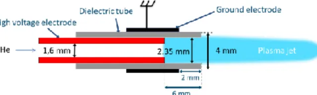
Our experimental device consists of a dielectric
tube (Øint=2.35 mm) separating two cylindrical
electrodes. The high voltage electrode is inside the tube while the outer electrode is grounded and glued to the tube (Fig. 1). The helium flow rate is such that the Reynolds number is typically between 100 and 600. A pulsed, high-voltage (3-5.5 kV) pulse with a rise time of 150 ns, duration of 400 ns, with frequency of 2 kHz-50 kHz is applied to the inner electrode. The grounded electrode is positioned 2 mm from the exit of the tube and the high voltage
Figure 1. Presentation of the device.
electrode is at 6 mm. Figure 1 is a schematic of our experimental device.
As has been noted previously [2], the helium flow has to be laminar at the exit of the dielectric tube in order for a plasma jet to propagate. In this communication we show Schlieren images of the helium jet with and without plasmas for various conditions of flow rate, applied voltage and frequency. For each condition we measure the distance from the exit of the dielectric tube to the point of the transition from laminar to turbulent regime.
2. Influence of Reynolds number
Figure 2 shows Schlieren images of the helium jet without (upper panel) and with (lower panel) plasma, the plasma operating at 20 kHz and 5.5 kV and for different Reynolds numbers - increasing gas flow rate - from left to right. The microdischarge is visible on the bottom of each figure. Each image shows a vertical distance of 10 cm from the exit of the microdischarge. It is apparent in this figure that for Reynolds numbers of about 250 and lower, the generation of a plasma jet leads to an upstream offset of the laminar-turbulent transition. Below a Reynolds number of 240 and without plasma, the transition point is outside the volume visible in the Schlieren images.
For higher Reynolds numbers, where the laminar-turbulent naturally transition occurs earlier, there is a decreasing influence of the plasma on the length of
the laminar zone. In typical plasma jet
configurations reported in literature, the Reynolds numbers range is from about 100 to 500.
Fig.2. Transition point without (upper panel) and with (lower panel) plasma as function of the Reynolds numbers. The plasma is generated by a 5.5 kV pulse operating at 20 kHz.
100 200 300 400 500 600 50 100 150 1.3 2.7 4.0 5.3 6.6 8.0 21 43 64 Gas flow rate (L·min-1
) Tran sition po int / Ø int Tran si tio n p oi nt (mm) Reynolds number without plasma with plasma
Dotted line = maximun Schlieren field of view
Fig. 3. Transition point without and with plasma as function of the Reynolds numbers, taken from the data shown in fig. 2.
3. Influence of applied voltage
We measured the transition point in the same configuration as described above for applied voltages from 3.0-5.5 kV and for different Reynolds numbers. These results are shown in fig. 4 for Reynolds numbers of 200 and 550 as a function of the applied voltage. We see that for low Reynolds numbers (Re<250) the influence of plasma jet on the transition point is more important for higher applied voltage until about 4.5 kV beyond which the influence of the plasma is constant. For higher Reynolds numbers, there is no obvious influence of the plasma on the transition point.
3.0 3.5 4.0 4.5 5.0 5.5 50 100 150 21 43 64 Tran sition po int / Ø int Tran si tio n p oi nt (mm) Voltage (kV) With plasma Re=200 Re=550 Without plasma Re=200 Re=550
Fig. 4. Transition point as function of the applied voltage for two Reynolds numbers. The plasma is generated by a pulse operating at 20 kHz.
4. Influence of operating frequency
The transition point as a function of frequency of the applied voltage is shown in fig. 5 for 4.2 and 5 kV. The Reynolds number for these results is fixed at 240, which corresponds to a gas flow rate of
3.2 L·min-1. The length of the laminar region
depends on the frequency of generation of the plasma bullets, decreasing by up to 30% as the plasma jet frequency increases from 2 kHz to 12 kHz, and thereafter remaining constant for operating frequencies up to 50 kHz (the highest frequency available for these experiments).
5 10 15 20 25 30 35 40 45 50 50 60 70 80 90 21 26 30 34 38 Tran sition po int / Ø int Tran si tio n p oi nt (mm) Frequency (kHz) 4.2 kV 5 kV
Fig. 5. Transition point as function of the applied frequency for two voltages for a Reynolds number of 240.
5. Conclusion
These measurements of the position of the transition point from laminar to turbulent regime show that the plasma has an influence on the hydrodynamics of the helium jet. This influence is more important for lower Reynolds numbers and higher voltages. The influence of the plasma is more important for higher operating frequency, but the
effect appears to saturate for frequencies greater than about 12 kHz.
From studies of surfaces discharges in open air for flow control applications, it is known that the ion wind generated by the discharge can affect the gas velocity parallel to the surface in the boundary layer in such a way as to enhance the transition to turbulence [4]. The ion wind generated by the micro discharge used to trigger the plasma jet as well as by the plasma jet itself (guided by the air/helium interface) could have similar consequences on the transition in the helium jet.
6. References
[1] X. Lu, M. Laroussi, V. Puech, Plasma
Sources Sci. Technol. 21 (2012) 034005.
[2] M. Teschke, J. Kedzierski, E.G. Finantu-Dinu, D. Korzec, J. Engemann, IEEE Trans. Plasma Sci. 33 (2005) 310.
[3] X. Lu, M. Laroussi, J. Appl. Phys. 100 (2006) 063302.
[4] N. Benard, E. Moreau, J. Phys. D, 43 (2010) 145201.
Acknowledgments
This work was partially supported by the French “Agence Nationale de la Recherche” through the project ANR-2010-BLAN-0930 (PAMPA).