UNIVERSITÉ DE SHERBROOKE
Faculté de génie
Département de génie mécanique
Analyse des sources du bruit de jeu dans les
ventilateurs axiaux
Analysis of Tip Leakage Flow Noise Inception in Axial Fans
Thèse de doctorat
Specialité : génie mécanique
Dominic LALLIER-DANIELS
Jury: Stéphane MOREAU (directeur)
Philippe LAVOIE
Martin BROUILLETTE
Adrien MANN
Marlène SANJOSÉ
RÉSUMÉ
L’écoulement de jeu est un phénomène hautement complexe et inévitable dant les turbo-machines étant donné la nécessité de prévenir l’interférence des éléments statiques avec le rotor. Il mène cependant à des pertes potentiellement importantes au niveau de la performance aérodynamique ainsi qu’à une augmentation de la signature acoustique de ces machines. Les mécanismes associés à ce type d’écoulement secondaire ont été large-ment étudiés dans les dernières décennies, mais étant donné les phénomènes complexes en présence, l’espace limité ainsi que l’interaction de pièces en mouvement rapide, une investi-gation expérimentale in-situ de l’écoulement de jeu est souvent ardue et requiert l’emploi de techniques avancées. En conséquence, la caractérisation de ce mécanisme est encore incomplète et demeure un sujet d’actualité dans le monde de la recherche ; des analyses conjointes des aspects aérodynamique et aéroacoustique sont particulièrement rares. La présente thèse propose de tirer parti du potentiel des méthodes de simulation numérique d’écoulements fluide pour réaliser une étude aéroacoustique de l’écoulement de jeu dans les ventilateurs axiaux basse-vitesse. La méthode Lattice-Boltzmann a été choisie pour réaliser l’étude à cause de la capacité qu’elle a de réaliser simultanément une étude aérodynamique et aéroacoustique en propagation directe sur une série de ventilateurs basse-vitesse avec et sans virole tournante. Ceux-ci furent choisis en grande partie à cause de l’existence d’une banque de données expérimentale permettant de valider les résultats de simulation et dans l’optique de fournir une vue large sur les différents aspects géométriques et opérationnels pouvant avoir une influence sur la formation de l’écoulement de jeu.
Les résultats numériques ont été employés pour réaliser une analyse détaillée du champ associé à l’écoulement de jeu et permettre l’identification des sources de bruits rattachées à l’aide de techniques de visualisations basées sur l’emploi d’isosurfaces de critère λ2 et
l’emploi combiné de l’analogie acoustique de Ffowcs Williams et Hawkings et de visualisa-tions de fluctuavisualisa-tions de pression filtrés à la surface des rotors. La différence fondamentale dans le mécanisme de formation de l’écoulement de jeu entre les machines axiales avec et sans virole a été mis en évidence, mais l’apparition de composantes tonales dans le spectre acoustique associées à l’interaction des structures cohérentes provenant du jeu avec les pales des rotors a été observée dans tous les cas.
Dans le but de fournir une évaluation quantitative du champ de distorsion responsable de l’apparition de ce bruit tonal, une technique de corrélation spectrale précédemment employée pour la caractérisation d’instabilités dans les machines centrifuges a été adaptée à l’étude du champ inhomogène induit par l’écoulement de jeu dans la région de bout de pale et permettre l’évaluation de son effet sur la signature acoustique des machines axiales étudiées.
Mots-clés : Ventilateurs axiaux, Écoulement de jeu, Aéroacoustique, Simulation nu-mérique d’écoulements fluides
ABSTRACT
Tip leakage flow is a highly complex phenomena that is unavoidable in turbomachinery applications due to the fact that a tip clearance is required to prevent the interference of the static elements of a turbomachine system with the moving rotor. It can lead to poten-tially large performance losses by modifying the aerodynamic conditions surrounding the blade as well as increases in the sound radiation of the fan. Tip leakage flow mechanics have been extensively studied in the last few decades, but given the complex flowfields en-countered in turbomachine applications and the small geometric space coupled the moving parts of typical rotor geometries, in-situ experimental investigation of tip leakage flow is arduous at best, requiring advanced experimental setups, and at worst nigh impossible in normal turbomachine operation. As a result, the characterization of this highly complex phenomena is still incomplete and remains a very active research field. Furthermore, joint aerodynamic and aeroacoustic investigations are rare for that particular phenomena. The current study was designed to leverage the potential of CFD methods for the evalu-ation of tip leakage flow mechanics and its impact on the acoustic radievalu-ation of low-speed axial fans, which arguably represent the most common and simple archetype of fans. A relatively recent class of CFD method called the Lattice-Boltzmann Method (LBM) was used to jointly evaluate the aerodynamic and aeroacoustic performance of selected fan systems, both free-tipped and ring-shrouded configurations, with an available experimen-tal database to which the simulation data was compared. The fans were selected on to allow for an extensive foray into the mechanics of tip leakage flow for a wide variety of configurations and operating conditions.
The CFD results were leveraged to perform a detailed investigation of the tip clearance flowfield for each case and identify the noises sources associated with tip clearance flow using flow visualizations based on the λ2 criteria for the identification of vortical structures
and the combined use of the Ffowcs Williams and Hawkings’ acoustic analogy with filtered wall-pressure fluctuation maps of the blade surfaces. The stark contrast in the tip flow mechanics associated with free-tipped and ring-shrouded fans was made evident from this analysis, but tonal components in the acoustic spectra of each of the configurations related to tip clearance mechanisms were also identified as a result of the interaction of the coherent turbulent structures generated by the rotor blades.
In order to characterize the flow distortions reponsible for the identified narrowband noise, a spectral correlation technique previously used for the experimental characterization of flow instabilities in centrifugal fans that was adapted to quantify the distortions in the flow induced by the tip leakage flow and their impact of the acoustic radiation of the fan. The analysis is carried out on each of the fan configurations studied and the structure of the distortion fields responsible for the tonal noise radiated as a result of the interaction of the tip leakage flow with the rotor blades is investigated.
Keywords: Axial Fans, Tip Leakage Flow, Aeroacoustics, Computational Fluid Dy-namics
TABLE OF CONTENTS
1 Introduction 1
1.1 Context of the Study . . . 1
1.2 Framework of the Current Thesis . . . 2
1.3 Outline of the Thesis . . . 3
2 Literature Review 5 2.1 Context . . . 5
2.2 Noise Sources in Low-Speed Fans . . . 5
2.2.1 Rotational Noise Mechanisms . . . 6
2.2.2 Non-Rotational Noise Mechanisms . . . 7
2.2.3 Dominant Mechanisms during Nominal Operation . . . 9
2.3 Impact of Tip Gap Flow on Fan Characteristics . . . 10
2.3.1 Physics of Tip Leakage Flow . . . 10
2.3.2 Tip Leakage Flow Noise Investigations . . . 19
2.4 Literature Review Assessment . . . 30
3 Test Cases 35 3.1 Context . . . 35
3.2 Axial Free-Tipped Fan . . . 36
3.2.1 Rotating Controlled Diffusion Blade Fan . . . 36
3.2.2 USI7 Test Fan . . . 40
3.3 Free-Tipped Fan with Complex Tip Geometry . . . 44
3.4 Ring-Shrouded Fan Configuration . . . 49
3.4.1 Valeo Ring-Shrouded Fan . . . 51
3.4.2 Mahle-Behr Ring-Shrouded Fan . . . 53
3.5 Wrap-Up on the Test Cases . . . 55
4 Numerical Methods 59 4.1 Context . . . 59
4.2 Equations Governing Fluid Flow . . . 59
4.2.1 Reynolds Averaged Navier-Stokes (RANS) . . . 61
4.2.2 Large Eddy Simulation (LES) . . . 61
4.2.3 Direct Numerical Simulation (DNS) . . . 62
4.2.4 Lattice-Boltzmann Method (LBM) . . . 62
4.3 Presentation of the Lattice-Boltzmann Method . . . 63
4.4 Computational Aeroacoustics (CAA) . . . 66
4.4.1 Direct Acoustic Simulation . . . 66
4.4.2 Hybrid Acoustic Methods . . . 69
4.5 Conclusion on Numerical Methods . . . 73
5 Validation of Simulation Cases 75
5.1 Context . . . 75
5.2 Technical Considerations for the Validation of Turbomachinery Simulation Cases . . . 75
5.2.1 Dimensionless Coefficients for the Characterization of Turbomachinery 76 5.2.2 Spectral Analysis . . . 77
5.3 RCDB . . . 78
5.3.1 Presentation of the Numerical Setup . . . 78
5.3.2 Global Aerodynamic Performance Evaluation . . . 82
5.3.3 Blade Wake Velocity Data . . . 85
5.3.4 Acoustic Performance . . . 89
5.4 USI7 Test Fan . . . 94
5.4.1 Presentation of the numerical setup . . . 94
5.4.2 Aerodynamic Performance Evaluation . . . 96
5.4.3 Acoustic Performance Evaluation . . . 100
5.5 Free-Tipped Fan with Complex Tip Geometry . . . 102
5.5.1 Presentation of the AMCA Numerical Setup . . . 103
5.5.2 Presentation of the Anechoic Numerical Setup . . . 104
5.5.3 Aerodynamic Performance Evaluation . . . 106
5.5.4 Aeroacoustic Performance Evaluation . . . 110
5.6 Valeo Ring-Shrouded Fan Geometry . . . 113
5.6.1 Presentation of the Flush-Mounted Numerical Setup . . . 115
5.6.2 Presentation of the Ducted Numerical Setup . . . 116
5.6.3 Aerodynamic Performance Evaluation . . . 118
5.6.4 Aeroacoustic Performance Evaluation . . . 123
5.7 Mahle-Behr Ring-Shrouded Fan Geometry . . . 128
5.7.1 Aeroacoustic Performance Evaluation . . . 131
5.8 Conclusion on the Validation of Test Cases . . . 133
6 Detailed Investigation of Clearance Flowfield and Fan Noise Sources 135 6.1 Context . . . 135
6.2 Investigation of Tip Clearance Flow Topology . . . 135
6.2.1 Free-Tipped Fan Configurations . . . 136
6.2.2 Ring-Shrouded Fan Configurations . . . 142
6.3 Noise Source Identification for the Investigated Rotors . . . 146
6.3.1 Installation Effects and Noise - Ffowcs Williams and Hawkings’ Analysis and Wall-Pressure Fluctuations Filtering . . . 148
6.4 Conclusion on the Detailed Investigation of the Clearance Flowfield and Fan Noise Sources . . . 164
7 Investigation and Quantification of Narrowband Tip Leakage Flow Noise Mechanisms 169 7.1 Context . . . 169
7.2 Modal Analysis Method . . . 170
7.2.1 Specific Application of the Correlation Method to the Identification of Tip Leakage Flow Structures . . . 173
TABLE OF CONTENTS vii
7.3 Evaluation of the Strength of the Interactions from Correlated Modes . . . 174
7.4 Correlation Analysis Applied to Tip Leakage Flow of Studied Fans . . . 177
7.4.1 USI7 Fan . . . 177
7.4.2 RCDB Fan . . . 190
7.4.3 Bosch Configuration . . . 200
7.4.4 H380EC1 . . . 211
7.5 Conclusion on the Analysis of Narrowband Mechanisms . . . 234
8 Summary, Conclusion and Perspectives 237 9 Sommaire, conclusion et perspectives 247 A Wavelet Transform Theory 257 A.1 Wavelet Theory . . . 258
A.2 Selection of a Mother Wavelet . . . 259
A.3 Wavelet Transform – Signal Processing . . . 260
A.4 Special Considerations . . . 261
A.4.1 Wavelet Filtering . . . 261
A.4.2 Smoothing for Wavelet Coherence Estimation . . . 262
LIST OF FIGURES
2.1 Illustration of the Virginia Tech blade cascade and observed vortex struc-tures [Muthanna, 1998]. . . 13 2.2 Illustration of the tip flow structures identified [You et al., 2007]. . . 14 2.3 Illustration of overtip maps measured on the Deverson compressor. The
arrow represents the trajectory of the tip leakage vortex. [Weichert, 2011] . 16 2.4 Composition of the tip vortex as viewed by instantaneous vorticity. The tip
vortex is seen to be composed from several vortex filaments highlighted by the red spots. [Wu et al., 2011b]. . . 17 2.5 Illustration of Longhouse’s observations [Longhouse, 1978] (a) Illustration
of the tip vortex formation, (b) Tip flow pattern from lightly loaded to highly loaded conditions (c) Effect of tip clearance on turbomachine noise;; - - - 1.33%, — 0.09% chord tip clearance. . . 20 2.6 Illustration of the rotating shroud of the fan [Longhouse, 1978]. . . 21 2.7 Comparison of the performances of an axial fan with (—) and without (
--) a well designed ringshroud at different tip clearance value for (a) Noise levels (b) Aerodynamic performance. [Longhouse, 1978]. . . 22 2.8 Schematic representation of the RI spectral feature in the near-field and
its acoustic impact in the far-field [Pardowitz et al., 2012]. (RI=Rotating Instability, CN=Clearance Noise) . . . 24 2.9 Illustration of the tip region recirculation pattern in a ring-shrouded fan (a)
Axial velocity field (b) Coherent vortex structures highlighted by Q-factor contours in the rotor frame of reference and their evolution with increasing loading (top to bottom, left to right). [Magne et al., 2015] . . . 26 2.10 Sound spectra obtained through hybrid methods for a ring-shrouded fan
compared to the experiment. [Magne et al., 2015] . . . 27 2.11 Effect of the modification of a ring-shrouded fan tip clearance (a) Sketch of
the static acoustic ring added to the geometry (b) Histogram of coherent structure azimuthal velocity with and without the acoustic ring [Piellard et al., 2014] . . . 28 2.12 Effect of the acoustic ring on the sound spectra in the experiment. [Piellard
et al., 2014] . . . 29 2.13 Assessment of a modal prediction tool for tonal tip leakage flow noise from
coherent structures (a) Prediction of the acoustic effect from the coherent structures (b) Visualization of pressure fluctuations associated with modes of order 10 (left) and 15 (right) . . . 31 3.1 RCDB impeller in the 3-blade configuration. . . 37 3.2 Schematic view of the AFRD facility at MSU [Davoudi et al., 2016b] . . . 38 3.3 Rotating HWA near-wake measurement system for the RCDB fan (a)
Hot-wire traverse system overview (b) Close-up view of the hot-Hot-wire measure-ment probe [Cawood, 2012] . . . 39
3.4 PIV measurements carried out on the RCDB fan in the AFRD facility (a) PIV measurement setup (b) Illustration of the PIV measurement planes [Neal, 2010] . . . 40 3.5 Location of the imbedded pressure taps on the RCDB blades. Probes 1-25
are located chordwise, with probes 25A-B-C located at the trailing edge and spread out spanwise. [Barrent, 2015] . . . 41 3.6 USI7 impeller. . . 41 3.7 Schematic view of the ducted USI7 fan assembly a) USI7 impeller with
its hemispherical hub nose b) inlet bellmouth c) bearing and electric drive d) support struts (M8 threaded rods) e) optional external drive shaft f) hemispherical flow conditioner g) optional electric motor with integrated torque meter. Dimensions in mm. [Carolus et al., 2015] . . . 42 3.8 Schematic view of the aerodynamic test rig for the USI7 fan as seen from the
side a) ducted fan assembly b) electric motor with integrated torque meter c) settling chamber with filter screens d) adjustable throttle e) auxiliary fan f) flow straighteners g) calibrated nozzle inlet. Dimensions in mm. [Zhu, 2016] 43 3.9 Schematic view of the acoustic test rig for the USI7 fan viewed from the top;
a) ducted fan assembly b) flow straightener c) flow chamber duct d) down-stream microphone with slit tube and nose cone e) hot-film flow meter f) anechoic duct termination g) adjustable throttle h) upstream microphones i) semi-anechoic chamber j) air inlet floor aperture. Dimensions in mm. [Zhu, 2016] . . . 44 3.10 Pressure transducers incorporated on the shroud casing wall in the tip region
of the blades for the USI7 acoustic test rig. The transducers are numbered C01 to C30. [Zhu, 2016] . . . 45 3.11 Illustration of the blade-imbedded pressure transducers on the USI7 fan.
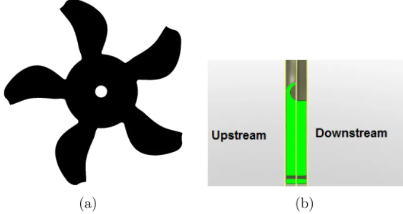
[Zhu, 2016] . . . 46 3.12 Illustration of the geometry of the automotive cooling fan (a) Fan rotor (b)
Axis cut of the shroud. . . 47 3.13 Schematic view of the Bosch test case duct assembly. . . 47 3.14 Schematic view of the AMCA test rig used for the experimental
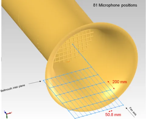
aerody-namic evaluation of the Bosch test case (a) Details of the AMCA flow chamber make-up (b) Surroundings of the AMCA flow chamber. . . 48 3.15 Schematic view of the anechoic test chamber setup for the Bosch test case. 49 3.16 Microphone array for the acoustic measurements on the Bosch test case. . 50 3.17 Representation of the H380 Valeo fan geometry and associated fixed shroud
geometry.[Soulat, 2010] . . . 51 3.18 Illustration of the Valeo flow facility (left) and reverberant room (right). . 52 3.19 Illustration of the H380 test rig for the ducted configuration (a) Numerical
model of the duct assembly with the H380 rotor, stator and conical plug presented in solid (b) Test rig in the anechoic wind tunnel chamber, with the semi-circular microphone array used for acoustic measurements visible in the forefront. . . 53
LIST OF FIGURES xi 3.20 Flow metering Prandtl probe setup for the H380 duct configuration (a)
ex-perimental setup (b) schematic view of the pitot configuration with regards to the duct termination plug. . . 54 3.21 Mahle CRFM geometry (a) View from upstream (b) View from downstream 54 3.22 Schematic representation of the AMCA test rig used for the Mahle fan tests. 55 3.23 Experimental test rig for the Mahle CRFM for the measurement of acoustic
emissions. . . 56 4.1 Representation of a possible permeable moving surface f (x, t) = 0 in the
FWH equation. [Farassat, 2007] . . . 71 5.1 Computational domain for the RCDB in the AFRD facility; not to scale. . 79 5.2 Mesh topology for the RCDB simulation (a) Overall view of the mesh (b)
Focus on the fan region . . . 80 5.3 Performance characteristic curve for the RCDB fan (3-blades).
Experimen-tal data from [Neal, 2010]. . . 82 5.4 Convergence of the pressure rise across the simulated RCDB cases (a) Case
1 (b) Case 2 (c) Case 3 . . . 83 5.5 Pressure coefficient profile at midspan for the RCDB along the normalized
chord xc at different operating conditions (a) OC1 (b) OC3 (c) OC5 . . . . 84 5.6 Instantaneous contours of chordwise velocity U around the midspan for the
RCDB at OC1 (a) Case 1 (b) Case 2 (c) Case 3 . . . 86 5.7 Schematic representation of the UVW coordinate system used for the
eval-uation of the wake velocity. . . 87 5.8 Single-blade phase-averaged wake velocity profiles for the RCDB fan in the
UVW frame of reference for OC1. . . 89 5.9 Single-blade phase-averaged wake velocity profiles for the RCDB fan in the
cylindrical frame of reference for OC3. . . 90 5.10 Acoustic radiation measured along the fan axis upstream of the RCDB fan
for operating point (a) OC1 (b) OC3 (c) OC5. ∆f = 2.1 Hz . . . 92 5.11 Comparison of the acoustic performance of the RCDB fan between the LBM
simulation direct results (Case 3) and experiment at (a) OC3 (b) OC5. The beamforming technique utilized by Davoudi [Davoudi et al., 2016a] was applied to the LBM microphone data for a proper comparison. . . 93 5.12 Simulation domain for USI7 . . . 95 5.13 Performance characteristic curve for the USI7 fan. . . 96 5.14 Wall-pressure spectra issued from the sensors imbedded in the rotating
blades in the tip region for the nominal flowrate case (φnom = 0.154)
∆f = 2 Hz . . . 98 5.15 Wall-pressure spectra issued from the sensors imbedded in the rotating
blades in the tip region for the nominal flowrate case (φpart−load = 0.131)
∆f = 2 Hz . . . 99 5.16 Acoustic sound power spectra for one of the off-axis microphone locations
for the USI7 fan for the considered operating points (a) φpart−load = 0.131
5.17 Computational domain for the Bosch fan in the AMCA configuration; not to scale . . . 103 5.18 Mesh topology for the Bosch fan in its AMCA configuration (a) around the
test duct (b) in the fan region . . . 105 5.19 Computational domain for the Bosch fan in the anechoic configuration . . 106 5.20 Mesh topology for the Bosch fan in the anechoic configuration (a) around
the test duct (b) in the region around the fan . . . 107 5.21 Performance characteristic curve for the Bosch fan. . . 108 5.22 Convergence of the pressure rise across the different Bosch fan simulations
(a) AMCA configuration (b) Anechoic configuration (c) Detailed view of a portion of the anechoic configuration pressure rise convergence . . . 109 5.23 Time-averaged velocity profiles in the wake of the Bosch fan rotor according
to the normalized radius in the cylindrical reference frame for the AMCA setup (a) Axial velocity (b) Radial velocity (c) Azimuthal velocity. . . 111 5.24 Acoustic sound power spectra for the Bosch fan anechoic setup for a
mi-crophone located at Pos(0)/Col(1) . The BPF harmonics are highlighted using vertical dashed lines. . . 112 5.25 Overall RMS acoustic pressure measured at microphone positions upstream
of the bellmouth inlet for the Bosch case. The numerical data is presented in dashed lines. . . 113 5.26 Filtered pressure field in the Bosch anechoic configuration simulation for
different inter-BPF frequency ranges (a) 330-360 Hz (b) 510-630 Hz (c) 710-800 Hz. . . 114 5.27 Computational domain for the H380 fan in the plenum configuration . . . 116 5.28 Computational mesh for the H380 fan plenum configuration (a) around the
test plenum (b) in the region around the fan . . . 117 5.29 Computational domain for the H380 fan duct configuration; not to scale . . 118 5.30 Computational mesh for the H380 fan duct configuration (a) around the
test duck (b) in the region around the fan . . . 119 5.31 Performance characteristic curve for the H380 fan in the plenum configuration.120 5.32 Performance characteristic curve for the H380 fan in the ducted configuration.121 5.33 Dimensionless performance characteristic curve of H380 fan in the ducted
configuration in Exp 1. . . 121 5.34 Dimensionless performance characteristic curve for the H380 fan in the
ducted configuration fort he nominal rotor speed. . . 122 5.35 Phase-averaged velocity profiles collected 33 mm downstream of the trailing
edge for the H380 fan in the cylindrical reference frame (a) Axial velocity (b) Azimuthal velocity (c) Radial velocity. . . 124 5.36 Time-averaged meridional streamlines superimposed on contours of velocity
magnitude for the (a) Plenum H380 simulation (b) Ducted H380 simulation 125 5.37 Convergence of the acoustic signal across the H380 simulations (b) Plenum
configuration (b) Ducted configuration. . . 126 5.38 Acoustic power spectra (SWL) for the H380 plenum configuration. BPF
LIST OF FIGURES xiii 5.39 Acoustic power spectral density spectra for the H380 ducted configuration
recorded 1.5 m upstream of the fan along the rotational axis. ∆f =2 Hz. BPF harmonics are highlighted by vertical dashed lines. . . 129 5.40 RMS acoustic pressure level in dB at 1.5 m on the suction side of the H380
duct configuration. . . 130 5.41 Semi-anechoic simulation domain for the Mahle cooling module. [Piellard
et al., 2014] . . . 131 5.42 Comparison of the acoustic pressure PSD from the direct CAA with the
experiment for two separate microphone locations (a) Microphone 2 (b) Microphone 14 . . . 132 6.1 Tip clearance flow highlighted by contours of λ2 for the USI7 colored by
vorticity magnitude. [Zhu, 2016] . . . 137 6.2 Illustration of the tip clearance flow structure for the RCDB simulation
(Case 3) highlighted by isosurfaces of λ2 (colored by vorticity magnitude)
at different flowrates (a) Nominal operating point (OC1) (b) Free-flow op-erating point (OC3) (c) Low flowrate opop-erating point (OC5) . . . 139 6.3 Acoustic PSD of the RCDB fan measured at 1 m along the rotational axis
for all three simulated operating conditions. . . 140 6.4 Tip clearance flow highlighted by isosurfaces of λ2 = −50 colored by
vortic-ity magnitude for the Bosch converging shroud configuration at the nominal flowrate. . . 141 6.5 Illustration of the tip clearance flow structure for the H380 simulation
high-lighted by isosurfaces of λ2 = −100 colored by vorticity magnitude for the
(a) Ducted configuration (b) Plenum configuration . . . 143 6.6 Throughflow view colored by instantaneous contours of circumferential
ve-locity normalized by the local blade speed for the H380 fan for the (a) Ducted configuration (b) Plenum configuration . . . 145 6.7 Vortical field around the Mahle fan as identified by isosurfaces of λ2 = −800,
colored by vorticity magnitude. . . 146 6.8 Instantaneous velocity field directly upstream of the Mahle fan (a)
Az-imuthal velocity normalized by the relative tip speed (b) Axial velocity (c) Radial velocity. The velocities are in m/s. . . 147 6.9 FWH analysis of the USI7 configuration for the part-load operating
condi-tion and large clearance gap. The BPFs are highlighted by vertical dashed lines. . . 149 6.10 Filtered wall-pressure fluctuations on the pressure side (left) and suction
side (right) of the USI7 fan at the part-load flowrate for the large clearance for frequency bands associated with tonal tip clearance noise (a) 340-360Hz (b) 505-525Hz . . . 150 6.11 FWH analysis of RCDB configuration at (a) Nominal OC1 (b) Near-stall
6.12 Filtered wall-pressure fluctuations on the pressure side (left) and suction side (right) of the RCDB fan at OC5 for frequency bands associated with tonal noise under 100 Hz (a) 19-35Hz (b) 35-46Hz (c) 46-60Hz (d) 60-76Hz (e) 76-104Hz . . . 153 6.13 FWH analysis of the Bosch configuration. The BPFs are highlighted by
vertical dashed lines. . . 154 6.14 Filtered wall-pressure fluctuations on the Bosch fan pressure side (left) and
suction side (right) for the frequency bands associated with sub-harmonic humps in the acoustic spectra (a) 143-203 Hz (b) 361-430Hz (c) 537-612Hz (d) 695-768Hz . . . 155 6.15 FWH analysis of H380 configuration in the (a) Ducted configuration (b)
Comparison of the FWH results between the ducted and plenum configu-rations. The BPFs are highlighted by vertical dashed lines. . . 157 6.16 Filtered rotor wall-pressure fluctuations on the suction side (left) and
pres-sure side (right) of the blades for the H380 in the ducted configuration in frequency bands corresponding to the observed acoustic sub-harmonic humps (a) 225-365 Hz (b) 530-670 Hz (c) 780-865 Hz (d) 1045-1220 Hz . . 158 6.17 Filtered rotor wall-pressure fluctuations on the suction side (left) and
pres-sure side (right) of the blades for the H380 in the plenum configuration in frequency bands corresponding to the observed acoustic sub-harmonic humps (a) 225-365 Hz (b) 530-670 Hz (c) 780-865 Hz (d) 1045-1220 Hz . . 159 6.18 Separation of the surface sources on the fan module (a)View from upstream
(b) View from downstream . . . 160 6.19 Acoustic pressure PSD for two separate microphone locations, comparing
the FWH predictions using the solid formulation (with ground reflection) and porous formulation for the second simulation (a) Microphone 2 (b) Microphone 14 . . . 161 6.20 Decomposition of the contributions of the different surface sources on the
Mahle configuration for microphone 2 . . . 162 6.21 PSD of wall-pressure fluctuations on the fan, stator and electrical motor
surfaces for the 232-358 Hz frequency range (O12-14) for the Mahle fan. . . 164 6.22 Illustration of the interior of the fan hub. . . 165 7.1 Illustration of the wavelet weighting method employed in the proposed
modal method (a) Wavelet transform of a pressure signal extracted in the tip region of the Bosch acoustic simulation (b) LIM values of the wavelet transform of the pressure signal (c) LIM-filtered wavelet coefficient ma-trix of the signal (d) Frequency-amplitude representation obtained through time-averaging of the LIM-filtered wavelet coefficient matrix . . . 176 7.2 Acoustic sound power spectra for one of the off-axis microphone locations
for the USI7 fan for the φpart−load = 0.131 operating point. . . 178
7.3 Power spectral density of two subsequent signals extracted from the USI7 LBM simulation data. The lead signal is in black and the trailing signal is in grey. . . 179
LIST OF FIGURES xv 7.4 Illustration of the intermediary steps of the correlation analysis for a pair
of probes in the USI7 LBM volume data. Cross-spectral coherence level Cxy (top), cross-spectral density amplitude (middle), phase lag between the
signals (bottom) . . . 180 7.5 Characteristics of the modes identified as a result of the correlation analysis
for a pair of probes in the USI7 LBM volume data. . . 181 7.6 Color-coding of the modal analysis positions according to radial (R) and
chordwise (C) positions for the USI7 fan. . . 182 7.7 Characteristics of the modes detected through correlations analysis for the
USI7 configuration in the tip region (R146-122) of the blades (a) Mode orders (b) Mode rotational velocity. . . 183 7.8 Instantaneous vortical field around the USI7 highlighted by isosurfaces of
λ2 = −200 (a) Raw λ2 field, colored by the the normalized rotational
veloc-ity nmod/nf an (b) λ2 field corresponding to 0.1 ≤ nmod/nf an ≤ 0.5 (c) and
(d) show the same field as (b) further filtered according to frequency in the 340-360 Hz (m = 10) and 505-525 Hz (m = 15) bands, colored by pressure amplitude (10 Pa). . . 185 7.9 Vortical structures corresponding to the correlation analysis modes in a
single blade passage. . . 187 7.10 Modal velocity of the detected modes in Zone 2 for the USI7 fan. . . 188 7.11 Histogram identifying the interaction frequencies of the detected modes for
the USI7 according to (a) Frequency of occurrence (b) Strength of the inter-actions as weighted by the wavelet thresholding method; the acoustic FWH prediction (black) and direct CAA (grey) spectra are overlaid. Binning is carried out at 10ths of the rotational frequency of the fan. . . 189 7.12 Power spectral density of two subsequent signals extracted from the RCDB
LBM volume data for OC5. The lead signal is in black and the trailing signal is in grey. . . 192 7.13 Illustration of the intermediary steps of the correlation analysis for a pair
of probes in the RCDB LBM volume data for OC5. Cross-spectral coher-ence level Cxy (top), cross-spectral density amplitude (middle), phase lag
between the signals (bottom) . . . 193 7.14 Characteristics of the modes identified as a result of the correlation analysis
for a pair of probes in the RCDB LBM volume data for OC5. . . 194 7.15 Color-coding of the modal analysis positions according to radial (R) and
chordwise (C) positions for the RCDB fan. . . 195 7.16 Characteristics of the modes detected through correlations analysis for the
RCDB configuration in the tip region (R365-341) of the blades (a) Mode orders (b) Mode rotational velocity. . . 196 7.17 Instantaneous vortical field around the RCDB fan at OC5 highlighted by
isosurfaces of λ2 = −10 (a) Raw λ2field, colored by the the normalized
rota-tional velocity nmod/nf an (b) λ2 field corresponding to 0.15 ≤ nmod/nf an ≤
0.45 (c) (d) show the same field as (b) further filtered according to fre-quency in the 90-110 Hz (m = 20) and 160-180 Hz (m = 30) bands, colored by pressure. . . 197
7.18 Histogram identifying the interaction frequencies of the detected modes for the RCDB OC5 according to (a) Frequency of occurrence (b) Strength of the interactions as weighted by the wavelet thresholding method. Binning is carried out at 10ths of the rotational frequency of the fan. . . 198 7.19 Power spectral density of two subsequent signals extracted from the Bosch
LBM volume data. The lead signal is in black and the trailing signal is in grey. . . 201 7.20 Illustration of the radii evaluated in the uppermost region of the span (a)
R154-94% span only evaluates the leading edge bulge of the blade ( (b) R150- 70% span and below cover the entire axial width of the fan. . . 202 7.21 Illustration of the intermediary steps of the correlation analysis for a pair
of probes in the Bosch LBM volume data. . . 203 7.22 Characteristics of the modes identified as a result of the correlation analysis
for a pair of probes in the Bosch LBM volume data. Cross-spectral coher-ence level Cxy (top), cross-spectral density amplitude (middle), phase lag
between the signals (bottom) . . . 204 7.23 Color-coding of the modal analysis positions according to radial (R) and
chordwise (C) positions for the Bosch fan. . . 205 7.24 Characteristics of the modes detected through correlations analysis for the
Bosch configuration in the tip region (R154-130) of the blades (a) Mode orders (b) Mode rotational velocity. . . 206 7.25 Instantaneous vortical field around the RCDB fan at OC5 highlighted by
isosurfaces of λ2 = −50 (a) Raw λ2 field (b) λ2 field corresponding to
−0.1 ≤ nmod/nf an ≤ 0.4, colored by the normalized rotational velocity
nmod/nf an (c) same field as (b) further filtered according to frequency in
the 530-550 Hz (m = 20) band, colored by pressure. . . 207 7.26 Histogram identifying the interaction frequencies of the detected modes for
the Bosch fan according to (a) Frequency of occurrence (b) Strength of the interactions as weighted by the wavelet thresholding method; the acous-tic FWH prediction (black) and direct CAA (grey) spectra are overlaid. Binning is carried out at 10ths of the rotational frequency of the fan. . . . 210 7.27 Power spectral density of two subsequent signals extracted from the H380
LBM volume data for the (a) ducted configuration (b) plenum configuration. The lead signal is in black and the trailing signal is in grey. . . 212 7.28 Illustration of the intermediary steps of the correlation analysis for a pair
of probes in the H380 LBM volume data in the (a) ducted and (b) plenum configurations . . . 214 7.29 Characteristics of the modes identified as a result of the correlation analysis
for a pair of probes in the H380 LBM volume data in the (a) ducted and (b) plenum configurations. . . 215 7.30 Color-coding of the modal analysis positions according to radial (R) and
chordwise (C) positions for the H380 fan. . . 216 7.31 Characteristics of the modes detected through correlations analysis for the
H380D configuration in the tip region (R182-173) of the blades for the 40-300 Hz range (a) Mode orders (b) Mode rotational velocity. . . 217
LIST OF FIGURES xvii 7.32 Histogram identifying the interaction frequencies of the detected modes
for the H380D fan for the 40-300 Hz range according to (a) Frequency of occurrence (b) Strength of the interactions as weighted by the wavelet thresholding method; the acoustic FWH prediction is overlaid. Binning is carried out at 10ths of the rotational frequency of the fan. . . 219 7.33 Histogram identifying the interaction frequencies of the detected modes in
the 40-600 Hz range for the H380D fan according to the strength of the interactions as weighted by the wavelet thresholding method; the acoustic FWH prediction is overlaid. Binning is carried out at 10ths of the rotational frequency of the fan. . . 220 7.34 Histogram identifying the interaction frequencies of the detected modes in
the 40-1000 Hz range for the H380D fan according to the strength of the interactions as weighted by the wavelet thresholding method; the acoustic FWH prediction is overlaid. Binning is carried out at 10ths of the rotational frequency of the fan. . . 221 7.35 Characteristics of the modes detected through correlations analysis for the
H380D configuration in the tip region (R182-173) of the blades for the 40-1000 Hz range (a) Mode orders (b) Mode rotational velocity. . . 222 7.36 Instantaneous vortical field around the H380D fan highlighted by isosurfaces
of λ2 = −100 (a)field corresponding to 0.1 ≤ nmod/nf an≤ 0.6 for the H380D
fan, colored by the the normalized rotational velocity nmod/nf an; (b) shows
the same field as (a) further filtered according to frequency in the 340-360 Hz (m ∼ 14 − 16) bands, colored by pressure. . . 223 7.37 Characteristics of the modes detected through correlations analysis for the
H380P configuration in the tip region (R182-161) of the blades for the 40-300 Hz range (a) Mode orders (b) Mode rotational velocity. . . 225 7.38 Instantaneous vortical field around the H380P fan highlighted by isosurfaces
of λ2 = −100 (a) field corresponding to 0.1 ≤ nmod/nf an ≤ 0.6 for the
H380P, colored by the the normalized rotational velocity nmod/nf an; (b)
show the same field as (a) further filtered according to frequency in the 340-360 Hz (m ∼ 14 − 16) bands, colored by pressure. . . 228 7.39 Histogram identifying the interaction frequencies of the detected modes for
the H380P fan for the 40-300 Hz range according to (a) Frequency of oc-currence (b) Strength of the interactions as weighted by the wavelet thresh-olding method; the direct CAA acoustic prediction is overlaid. Binning is carried out at 10ths of the rotational frequency of the fan. . . 229 7.40 Histogram identifying the interaction frequencies of the detected modes in
the 40-600 Hz range for the H380P fan according to the strength of the interactions as weighted by the wavelet thresholding method; the direct CAA acoustic prediction is overlaid. Binning is carried out at 10ths of the rotational frequency of the fan. . . 230
7.41 Histogram identifying the interaction frequencies of the detected modes in the 40-1000 Hz range for the H380P fan according to the strength of the interactions as weighted by the wavelet thresholding method; the direct CAA acoustic prediction is overlaid. Binning is carried out at 10ths of the rotational frequency of the fan. . . 231 7.42 Characteristics of the modes detected through correlations analysis for the
H380P configuration in the tip region (R182-161) of the blades for the 40-1000 Hz range (a) Mode orders (b) Mode rotational velocity. . . 232 7.43 Characteristics of the modes detected through correlations analysis for the
H380P configuration in the tip region (R170-161) of the blades for the 40-1000 Hz range at the leading edge (C01-C05) (a) Mode orders (b) Mode rotational velocity. . . 233 7.44 Histogram identifying the interaction frequencies of the detected modes for
the H380P fan for the 40-1000 Hz range for the R170-161 positions at the leading edge (C01-C05) according to the strength of the interactions as weighted by the wavelet thresholding method; the direct CAA acoustic pre-diction is overlaid. Binning is carried out at 10ths of the rotational frequency of the fan. . . 234
LIST OF TABLES
3.1 Dimensions of the Test Duct Assembly for the Bosch Fan Experimental Rigs 49 7.1 Proportion of events identified at different spatial points according to radius
and chordwise position in the tip region of the USI7 fan . . . 186 7.2 Amplitude-weighted proportion of events identified at different spatial points
according to radius and chordwise position in the tip region of the USI7 fan 188 7.3 Proportion of events identified at different spatial points according to radius
and chordwise position in the tip region of the RCDB fan . . . 193 7.4 Amplitude-weighted proportion of events identified at different spatial points
according to radius and chordwise position in the tip region of the RCDB fan199 7.5 Proportion of events identified at different spatial points according to radius
and chordwise position in the tip region of the Bosch fan . . . 208 7.6 Amplitude-weighted proportion of events identified at different spatial points
according to radius and chordwise position in the tip region of the Bosch fan208 7.7 Proportion of events identified at different spatial points according to radius
and chordwise position in the tip region of the H380D fan for the 40-300 Hz range . . . 218 7.8 Amplitude-weighted proportion of events identified at different spatial points
according to radius and chordwise position in the tip region of the H380D fan for the 40-300 Hz range . . . 218 7.9 Proportion of events identified at different spatial points according to radius
and chordwise position in the tip region of the H380P fan for the 40-300 Hz range . . . 226 7.10 Amplitude-weighted proportion of events identified at different spatial points
according to radius and chordwise position in the tip region of the H380P fan for the 40-300 Hz range . . . 226
CHAPTER 1
Introduction
1.1
Context of the Study
Turbomachine systems are an integral part of everyday life in the modern world. Every-day applications encountered include Heating, Ventilation and Air Conditioning (HVAC) systems, cooling systems in the transportation industry (e.g. automotive engine cooling fans), cooling fans for consumer electronics, compressor units in food refrigeration appli-ances; one could extend the list to include high-speed rotors used in aircraft propulsion, as the air transportation market is slated to keep growing at a fast rate through 20371.
However, the vast majority of the machines routinely encountered in a typical day can be classified in the low-speed fan category. They are often invisible to the naked eye, for security as well as aesthetic reasons, but also to mask their presence which can be felt through other means, not the least of which is through the noise they radiate. This acoustic contribution can be an annoyance in some cases or devolve into a health issue after prolonged exposure.
As a result, perpetually evolving performance standards for turbomachine operation, both aerodynamic and acoustic, are put in place to protect the public from any adverse effects, leading rotating machine designers to scramble and improve their design methodologies to meet these requirements. Turbomachine design is however a complex process in and of it-self given the intricate flowfields encountered in such rotating machines and the sometimes very variable flow conditions they are exposed to. Furthermore, unwanted flow phenomena incurring losses and/or increased noise are inevitable even with careful design procedures as they are still ill-understood and not taken into account properly.
One of these unwanted phenomena occurs because of the tip clearance that is required to prevent the interference of the static elements of a turbomachine system with the moving rotor that is imparting (compressor, fan, pump) or retrieving (turbine) energy from the fluid flow, depending on the vocation of the system. That particular flow phenomena is called tip leakage flow (TLF) and is characterized by a passage of a certain portion of the fluid from the pressure side (high pressure) of a turbomachine blade towards its suction side
1. FAA Aerospace Forecast 2017-2037; https://www.faa.gov/data_research/aviation/ aerospace_forecasts/media/FY2017-37_FAA_Aerospace_Forecast.pdf
(low pressure) across the tip clearance gap, forming a strong cross-flow perpendicular to the blade chord that is the turbomachine equivalent of the tip flow formed at the tip of finite aircraft wings. This flow in and of itself as well as its interaction with the throughflow in the machine leads to the creation of potentially large losses by modifying the aerodynamic conditions surrounding the blade as well as creating large turbulent structures that are convected in the passage flow. In addition to aerodynamic losses, tip leakage flow and the fluid phenomena that are created as a result of it can contribute to a large degree to the acoustic footprint of the affected turbomachine systems.
Tip leakage flow mechanics have been studied in the last few decades, with some stud-ies dating as far back as the 1940s, with most of the investigative work being carried out through experiments. However, given the complex flowfields encountered in turbo-machine applications and the small geometric space coupled the moving parts of typical rotor geometries, in-situ experimental investigation of tip leakage flow is arduous at best, requiring advanced experimental setups, and at worst nigh impossible in normal turbo-machine operation. As a result, the characterization of this highly complex phenomena is still incomplete and it is still a very active research field. Furthermore, joint aerodynamic and aeroacoustic investigations are rare for that particular phenomena.
In parallel, the last decades have seen the emergence of computational fluid dynamics (CFD) as a way to simulate and more easily investigate such complex flowfields, with the advent of exponentially more powerful computers showcasing parallel processing capabil-ities and the continuous improvements in the numerical methods employed for simulating fluid flows. These numerical methods, should they prove reliable in reproducing the actual flow physics of complex turbomachine systems as well as the associated acoustic radia-tion, would prove an invaluable tool for joint aerodynamic/aeroacoustic investigations of tip leakage flow mechanics and the associated noise as well as for several other phenomena.
1.2
Framework of the Current Thesis
The current study was designed to leverage the potential of CFD methods for the evalu-ation of tip leakage flow mechanics and its impact on the acoustic radievalu-ation of low-speed axial fans, which arguably represent the most common and simple archetype of fans. The chosen method is thus required accurately represent the highly unsteady and turbulent flow features associated with the TLF phenomena. Concurrently, it must also be able to predict the acoustic radiation resulting from the interaction with the rotor blades numer-ically (Computation Aeroacoustics, CAA).
1.3. OUTLINE OF THE THESIS 3 While this is theoretically achievable using so-called traditional unsteady CFD codes based on the Navier-Stokes equations (i.e. Large-Eddy Simulations, LES and Direct Numerical Simulations, DNS), it would require impractical amounts of computational resources for the direct propagation of the aeroacoustic properties in a realistic environment using these methods.
A relatively recent class of CFD method called the Lattice-Boltzmann Method (LBM), however, shows promise in that regard and has seen its usage grow in recent years, espe-cially in the field of turbomachinery modeling for low-speed machines. Thus, one of the objectives of the current work was to evaluate the potential of the LBM for such a special-ized study, which would allow for a joint aerodynamic/aeroacoustic investigation of TLF for complex configurations. To carry out the performance evaluation of the method, a se-ries of low-speed fan geometse-ries for which extensive experimental databases were available were evaluated in the course of the current work; they are described in Chap. 3 and include both free-tipped as well as ring-shrouded fan geometries. This allowed for the comparison of the numerical results with those from the experiments, as shown in Chap. 5.
The selected configurations allowed to evaluate the topology and acoustic impact of tip leakage flow for varied tip geometries. However, the investigated fan systems were op-erated in fairly different environments (test rigs), and the LBM simulations were setup to accurately represent and capture the differences between them, so the impact of the test environment on the formation of TLF and the associated acoustic impact could be investigated.
1.3
Outline of the Thesis
As a first step in this investigation of TLF, a review of the literature on the subject is first presented in Chap. 2. An overview of the noise mechanisms in low-speed fans is first presented, and their relative importance is qualitatively graded. A literature review on the subject of TLF specifically is then carried out, covering both the aerodynamic and aeroacoustic aspects.
The various fan configurations selected for the study of tip leakage flow in the course of this work are then described in Chap. 3. A total of 5 fan geometries were selected for investigation, with three from the free-tipped archetype of fans and two ring-shrouded rotors. The test rigs employed for the experimental characterization of each of these fans as well as the available data are detailed.
Chap. 4 introduces the numerical methods available for the purpose of carrying out a CAA investigation of tip leakage flow on the proposed geometries. The expected performance of classical unsteady CFD methods (LES, DNS) is measured against the emerging LBM for the purpose of carrying out direct aeroacoustic simulations. An informative section of so-called hybrid CAA methods is also presented, with a certain emphasis placed on a very powerful tool in the field of turbomachinery called the Ffowcs Williams and Hawkings (FWH) analogy.
In Chap. 5, the predictive performance of the LBM for the five studied geometries is evaluated by comparing the simulations with the available experimental data, from both the aerodynamic and the direct acoustic point of view.
A specific investigation of the tip leakage flow topology and associated acoustics is pre-sented out in Chap. 6. The coherent structures generated by the TLF around the studied configurations are visualized using the λ2 criterion proposed by Jeong and Hussain [Jeong
and Hussain, 1995] using the unsteady volumetric data recorded in the simulations. The difference in the tip leakage flow mechanics between free-tipped and ring-shrouded fans is highlighted. The identification of the acoustic signature of the TLF is carried out using an approach based on the FWH analogy and the use of band-pass filtering techniques on the wall-pressure fluctuations from the rotor surface. The use of the FWH analogy is neces-sary to delineate the specific acoustic contribution of the fan from the installation effects which dominate the spectra for some of the configurations. The occurrence of quasi-tonal noise is linked to the presence of flow distortions generated by the tip leakage flow in the tip region of the blades.
Chap. 7 presents a spectral correlation technique previously used for the experimental characterization of flow instabilities in centrifugal fans [Bent, 1993; Bent et al., 1993; Mongeau et al., 1993] that was adapted to quantify the distortions in the flow induced by the tip leakage flow and their impact of the acoustic radiation of the fan. The analysis is carried out on each of the fan configurations studied and the structure of the distortion fields responsible for the tonal noise radiated as a result of the interaction of the tip leakage flow with the rotor blades is investigated.
Finally, Chap. 8 contains a summary of the work carried out and results obtained in the course of this thesis and highlights the main observations that can be drawn from this work.
CHAPTER 2
Literature Review
2.1
Context
In even the most carefully designed turbomachines, unwarranted flow phenomena having negative impacts on turbomachine operation are bound to occur. However, as there is a large variety in the shape and size of the various rotating machines, each individual case is slightly (or in some cases very) different from the next. The intended application of the machine may also emphasize the importance of controlling these flow phenomena. Turbomachinery design is thus a very complex process in and of itself, and is subjected to increasingly strict standards, be they self-imposed by manufacturers to improve market shares or meet required specifications, legislative in nature, or as a result of novel design methods becoming the norm, such as those based upon computational fluid dynamics (CFD).
Historically, a large emphasis on aerodynamic performance has driven development meth-ods forward, especially improvements in efficiency of designed machines. However, unde-sirable flow phenomena incurring losses are inevitable even with careful design. In the last decades, the added complexity of more stringent regulations on the allowable noise levels for given applications has become critical in many engineering applications such as transportation (e.g. aeroengines, cooling systems) or ventilation systems for example. As manufacturers are quickly discovering, controlling the noise levels of novel machines at the design stage is a daunting task and requires knowledge of the mechanisms in play, therefore driving research and development in the field of turbomachinery aeroacoustics. This chapter proposes a brief review on the subject of fan acoustics, with an emphasis on low-speed axial fans, which are arguably the most common type encountered in everyday life and are typically used when high flow rates are required.
2.2
Noise Sources in Low-Speed Fans
The possible noise sources in a turbomachinery environment are multiple and possibly very dependant on the installation in their occurrence and importance. Fan noise mechanisms can be classified into two categories: rotational and non-rotational noise ([Longhouse,
1976], [Roger, 2009], [Moreau, 2011]). The rotational noise sources are dependant on the periodic interactions of the rotor with the flow causing a fluctuation of the blade loading, which normally produces strong tones around the BPF and its harmonics. Non-rotational noise is however considered to occur due to random turbulence and is mostly considered to radiate as broadband noise, with some tonal noise normally uncorrelated with the BPF also occuring due to some mechanisms.
Here, the concern regarding the noise mechanisms of low-speed fans in a ducted ment is considered, with possible interactions from the installation in a realistic environ-ment also taken into account.
2.2.1
Rotational Noise Mechanisms
As explained before, rotational noise mechanisms are highly linked to the tonal noise near the BPF and its harmonics. These deterministic and periodic phenomena, when observed from the rotating frame of reference of the blades, cause periodic fluctuations in the blade loading and thus produce mainly tonal noise peaks.
Thickness Noise
The first rotational noise component which could be considered is the so-called thickness noise, which refers to the effect of the displacement of the fluid by the volume of the rotor blades themselves. This mechanism is however highly related to the compressibility of the fluid and is therefore more important at high rotor speeds and negligible in inhomogeneous low-speed applications where thickness noise will be drowned out by general turbulence in the passage flow [Caro and Moreau, 2000; Moreau, 2011; Roger, 2009].
Steady Blade Loading/Unsteady Blade Loading noise
The second source of noise takes root in the blade forces present on the blades themselves (loading noise). The blade load can be decomposed into two separate components: the steady blade load, which is the average blade force as seen from the perspective of the rotating blades, and an unsteady component which varies in a periodic manner during the course of one rotation of the blade due to natural turbulence in the boundary layer of the rotor blades or inhomogeneities in the inflow [Roger, 2009]. The rotation of these forces with the blades causes the appearance of a tonal noise component around the BPF and its hamonics. However, it should be noted that for low-speed applications, steady blade loading noise is negligible [Roger, 2009] and is dominated by unsteady blade loading effects.
2.2. NOISE SOURCES IN LOW-SPEED FANS 7 Flow Distortion Noise
To the inherent blade thickness and loading noise can be added the inference of instal-lation effects on the blade loading. A first source would be inflow distortions [Moreau, 2011]. These distortions can have different origins. For example, inflow distortions for an automotive cooling fan may be produced by struts present in the inlet portion of the fan assembly, forming a wake seen as a localized distortion of the flowfield periodically encountered by the rotating blades and causing a fluctuation of the blade loading, thus producing tonal noise. A second inflow distortion source which could be considered are the boundary layers developping on the hub and shroud surfaces of the fan assembly, dis-torting the flow locally on the blade near the hub and at the tip and causing fluctuating loading on the rotor blades. Thus the contouring of the duct surface to control boundary layer development is seen to have a rather important effect on both broadband and tonal noise levels of an axial fan as reported by [Maaloum et al., 2003].
To the inflow distortion effects can be added to the potential effects of downstream struc-tures on the blade loading ([Moreau, 2011; Roger, 2009]). Whereas strucstruc-tures situated upstream of the fan mainly cause inflow distortions, nearby structures situated down-stream may interact with the fan blades via their potential field, which diverts the flow due to their volume, causing more or less localized distortions of the flowfield and caus-ing fluctuatcaus-ing loads on the blades at frequencies near the BPF and its harmonics. This potential effect can also affect the inflow condition when strong blockage effects occur. In practice theses fluctuations may be caused by struts included in the fan assembly or any solid surface located in close proximity of the fan in the downstream section.
2.2.2
Non-Rotational Noise Mechanisms
The second class of noise mechanisms in turbomachinery applications is called non-rotational noise. They are caused by random turbulence and occur mainly as broadband noise with some tonal peaks.
Leading Edge Turbulence Ingestion
The first noise mechanism that can be identified is called leading edge or turbulence interaction noise. This mechanism stems from the interaction of the leading edge of the rotor blades with incoming random turbulence present in the flow or as a result of the ingestion of turbulent boundary layers; the turbulent eddies are scattered by the edge of the blades, thus producing wall-pressure fluctuations which propagate in the farfield as broadband noise [Carolus et al., 2007; Moreau and Roger, 2007]. It is to be noted that this
particular phenomena can be amplified by the interaction with inflow distortions, which produce additional localized turbulence in the flow.
Trailing Edge Broadband Noise (or Self-Noise)
A second mechanism that is considered the minimum noise imprint that would be produced by a fan with the absence of any outside influence is trailing edge noise [Moreau and Roger, 2007]. It can be seen as a scattering of the turbulent eddies in the boundary layer by the trailing edge of the profile as broadband noise. The influence of trailing edge noise is seen to increase with the Reynolds number (flow velocity); as well, the increase of the angle of attack appears to increase the levels of the radiated noise in the lower frequencies whilst leaving the higher frequencies relatively untouched for a given Reynolds number [Moreau and Roger, 2005; Rozenberg, 2007].
Vortex Shedding
In the presence of a laminar boundary layer and trailing edge bluntness on the rotor blades, a different mechanism can also be seen to appear at the trailing edge. Thus, vortex shedding and the appearance of a Von Karman street was seen to appear on an engine cooling fan at higher flowrates for certain fan geometries and a relatively limited range of operation [Longhouse, 1977]. The appearance of vortex shedding on the blades, which occurs at different frequencies along the blade given the different relative flow velocities, led to a general increase in broadband noise for the fans and to the appearance of several tonal peaks at high frequency attributable to the vortex shedding mechanism proper. Tip Leakage Noise
Finally, another mechanism considered as an important source of noise in low-speed axial fans is tip leakage noise. Tip leakage flow occurs across the tip from the pressure side to the suction side of any finite unshrouded aerodynamic body and is mainly driven by the pressure differential across the tip between the two surfaces and thus increases with blade loading. In turbomachinery applications, vortical structures are then formed in the adjoining passage flow in the tip area by the interaction with the relative free-flow. Tip leakage flow thus produces a highly turbulent flowfield in the tip area of the rotor blades. Several causes of increased noise as a result of tip clearance flow are identifiable. First, the diffraction of the tip leakage jet on the suction side of the tip of the blades [Grilliat, 2009; Mann et al., 2016] causes increased broadband noise levels. The turbulent structures generated by the tip leakage flow impinging on the shroud and following blades increases the wall-pressure fluctuations on the affected surface and results in increased broadband noise levels, with tonal noise also generated in some cases.
2.2. NOISE SOURCES IN LOW-SPEED FANS 9
2.2.3
Dominant Mechanisms during Nominal Operation
Even in nominal operating conditions, which is different for every fan design, experimental investigation of the dominant noise mechanisms is an arduous task at best given the complex flows and multiple interactions found in a turbomachine environment. However, some noise mechanisms identified in the previous section are found to have an important impact on the noise spectra of low-speed turbomachines.
First and foremost, tonal or quasi-tonal noise mechanisms related to rotational noise (fre-quencies around the BPF and harmonics) can most often be seen in the noise spectra or low-speed axial fans, sometimes dominating the broadband noise by several dB even without the presence of inflow disturbances other than the boundary layers on the hub and shroud surfaces, be they shrouded or unshrouded rotors [Carolus et al., 2007; Fukano and Jang, 2004; Longhouse, 1978; Moreau and Roger, 2007]. These quasi-tonal occurrences can be related to a strong influence of unsteady blade loading.
Trailing edge noise is also an important mechanism found to have an important influence on broadband noise levels. Apposing fabric to the trailing edge of a low-speed free tip axial fan was shows to result in several dB of reduction in broadband noise levels at high frequencies, especially in the 2-4 kHz band [Quinlan and Bent, 1998]. This is in phase with the results of trailing edge modeling where the trailing edge noise seems to correlate well with very high frequency components of the noise spectra of a shrouded fan [Moreau and Roger, 2007]. However, the leading edge turbulence ingestion noise is a concurrent noise mechanism and can easily dominate the blade trailing edge noise at lower frequencies depending on the turbulence levels of the flow [Carolus et al., 2007; Moreau and Roger, 2007]. Therefore, leading edge noise ingestion might also be an important noise mechanism.
Finally, it was shown by several authors that the tip clearance flow in axial turbomachines had a rather significant impact on fan noise. Some authors showed a large influence, for example, of the tip gap size on the noise spectra of tested axial fans [Fukano and Jang, 2004; Fukano et al., 1986; Longhouse, 1978; Quinlan and Bent, 1998]. In practice, a larger tip gap increases broadband noise of the fan, which is linked to the concurrent increase in strength and size of the tip leakage flow.
Detailed spanwise investigations also show the tip region of a tested axial fan as being an important contributor to the overall noise spectra using cross-correlation analysis [Bianchi et al., 2009]. The addition of tip flanges to control the formation of the tip leakage flow also achieves broadband noise reduction of several dB especially at high frequencies [Corsini
et al., 2007; Quinlan and Bent, 1998]. The addition of complete ringshrouds also shows a decrease of global noise levels in normal operation as a result of the modification of the tip leakage flow topology [Longhouse, 1978; Shimada et al., 2003]. Tip clearance noise is thus an important characteristic of the noise spectra in the operation of low-speed axial fans.
Significant research efforts were made over the last several decades to try and understand the physical mechanisms associated with tip leakage flow and to gain a better grasp of their impact of the aeroacoustic performance on turbomachinery systems. However, its inner-workings are still ill-understood to this day. The next section proposes a brief overview of relevant research conducted on the topic of tip leakage flow.
2.3
Impact of Tip Gap Flow on Fan Characteristics
Tip leakage flow is an unavoidable consequence of the finite span of real-life lifting aero-dynamic surfaces, from aircraft wings and propellers to turbomachine rotor blades. It can be responsible for introducing possibly drastic changes from the ideal flow conditions surrounding a given aerodynamic body and can degrade its performance characteristics. Tip leakage flow is essentially driven by the flow from the high pressure surface of an aero-dynamic body spilling over to the low pressure side. This cross-stream flow thus interferes with the chordwise throughflow along the aerodynamic body and is swept downstream. This results in velocity deficits in the main flow, modifying the local angle of attack and generating detached flow structures/vortices which are then free to interact with the in-volved geometry and impact the efficiency of the system further.
In the case of turbomachine applications appears the added complexity of the relative mo-tion of the blades as well as, in several cases, the proximity of a shroud surface influencing the shape and size of the tip clearance and the formation of the tip leakage flow features. In this section, an overview of the literature regarding tip leakage flow physics and their impact on the acoustic performance of turbomachine systems is proposed.
2.3.1
Physics of Tip Leakage Flow
Research on the physics of tip leakage flow is not a recent development, but it has proven to be a phenomenon difficult to investigate experimentally, requiring extensive and often costly mockups to be manufactured. Tip leakage and the flow features associated with it are also very complex in nature, appear highly dependant on the geometry and loading of
2.3. IMPACT OF TIP GAP FLOW ON FAN CHARACTERISTICS 11 the blade. They are also impacted by other flow phenomena such as upstream disturbances (e.g. turbulence coming from developping boundary layers or inlet guide vanes). Published work going back decades can be seen to be concerned with the influence of tip clearance flow on fan performance. Most of the work, though, was focused on the aerodynamic effect with little to no emphasis on the potential acoustic impacts. Based on literature from the 1940s and 1950s, tip leakage flow was lumped into what was and is still known as secondary flow losses, and experiments on full axial fans/compressors/pumps were carried out to study the inception and effects of tip clearance flow [Rains, 1954; Ruden, 1944; Ryan and Ohashi, 1955]. With measurement techniques used at the time however, only relatively base and global information about the flow could be collected (e.g. flow rate, head rise, efficiency, approximative flow angle behind the rotor trailing edge) in addition to mostly qualitative observations. This early research was however more concerned with developing empirical or semi-empirical models able to predict the fan efficiency/pressure rise as a function of the tip clearance gap, although Rains [Rains, 1954] tried to model the tip leakage vortex formation and allowed for a satisfactory prediction of the tip leakage losses incurred in an axial pump as well as a compressor geomery to which the model was applied.
One of the simplest representations of a rotor is arguably the linear cascade configuration. It is also easier to inspect the flow inside a stationary blade cascade than it is in a moving rotor assembly. Different authors, whose work is presented hereafter, have thus opted for this configuration to investigate tip gap flow effects on a more fundamental level. However, this configuration clearly has some differences with usual rotor setups: the solidity of the blades, which varies in a real rotor setup from hub to tip is fixed on a blade cascade model; the radial deviation of the flow that might be seen in real rotors due to centrifugal effects is not reproduced in such experiments; shear effects in the flow affected by the relative motion between the rotor blades and the shroud are not taken into account in most experiments; shroud curvature might have an effect on tip flow formation. It is, however an interesting way to investigate the basic mechanics of tip flow formation in a controlled environment for fixed parameters.
Kang and Hirsch ([Kang and Hirsch, 1993, 1994]) performed measurements on a 7 blade linear compressor cascade using five-hole probes and oil flow visualizations (Reynolds number of 290 000 based on a 200 mm chord). They observed the formation of a tip cross-flow perpendicular to the blade, rolling up at the suction side to form the tip vortex structure when encountering the free-flow. A short distance after the midchord point, the tip flow is seen separating from the blade, rolling up into a smaller vortex structure (tip
separation vortex). They also observed a horseshoe vortex forming near the tip leading edge in close proximity to the tip leakage vortex on the suction side of the blade; this vortical structure could be related to the induced vortex observed by You et al. [You et al., 2007] whose work will be detailed shortly. In all, three main vortical structures are seen appearing from the tip leakage flow. They identified the tip leakage vortex as the main source of vorticity near the passage endwall, with its area of dominance moving away from the blades and inwards spanwise as it is convected downstream. Intense mixing loss is also identified in the aft portion of the profile.
A more complex series of experiments was carried out at Virginia Tech on a linear cascade in order to investigate the inception of tip gap flow features. Work was carried out on a 8 blade compressor cascade at a Reynolds number around 450 000 based on a 254 mm chord length, corresponding to a Mach number of 0.08. Muthanna [Muthanna, 1998], using hotwire sensors, pressure taps and surface oil visualizations, observed the formation of the aforementioned cross-flow perpendicular to the chord across the tip clearance of the blade cascade. The cross-flow then rolled up into the so-called tip leakage vortex (TLV) when encountering the free-stream at the suction side and peeling away towards the pressure side of the following blade. A secondary vortex structure with opposing but relatively lower vorticity when compared to the tip vortex also formed near the suction side tip edge. Varying the tip clearance also influenced the observed vortices, with a larger gap increasing the TLV strength and zone of influence, and moving its detachment point along the blade chord. On the opposite side of the spectrum, a small enough gap prevents the formation of the TLV, instead leading to the formation of a high shear flow layer along the shroud casing originating from the clearance gap. It was observed, however, that with the TLV present, it becomes the main source of turbulence in the flowfield, dominating even the blade wakes downstream of the blade cascade. Wang [Wang, 2000] investigated the effect of adding a moving shroud wall to simulate the relative movement between the blades and the shroud casing in a functional rotor assembly. It was found that it only served to flatten the TLV in the spanwise direction, but did not interfere with the mechanisms behind the formation of the structures. Their findings were also confirmed by laser Doppler velocimetry measurements [Tang, 2004].
The effect of increased upstream general turbulence was also investigated [de la Riva, 2001; Muthanna, 2002]. It was found that a 3% turbulence intensity at the inlet of the cascade had some effect on the tip clearance flow. A decrease in the blade loading was readily observed, as well as a diminution of the vorticity levels inside the TLV by about 20% combined with an increased vortex core size of around 30%. It is interesting to note that
![Figure 2.5 Illustration of Longhouse’s observations [Longhouse, 1978] (a) Illus- Illus-tration of the tip vortex formation, (b) Tip flow pattern from lightly loaded to highly loaded conditions (c) Effect of tip clearance on turbomachine noise;; -- 1.33%,](https://thumb-eu.123doks.com/thumbv2/123doknet/2697015.62959/44.918.165.730.323.899/illustration-longhouse-observations-longhouse-formation-conditions-clearance-turbomachine.webp)

![Figure 2.8 Schematic representation of the RI spectral feature in the near-field and its acoustic impact in the far-field [Pardowitz et al., 2012]](https://thumb-eu.123doks.com/thumbv2/123doknet/2697015.62959/48.918.261.644.758.994/figure-schematic-representation-spectral-feature-acoustic-impact-pardowitz.webp)


![Figure 2.11 Effect of the modification of a ring-shrouded fan tip clearance (a) Sketch of the static acoustic ring added to the geometry (b) Histogram of coherent structure azimuthal velocity with and without the acoustic ring [Piellard et al., 2014]](https://thumb-eu.123doks.com/thumbv2/123doknet/2697015.62959/52.918.145.770.398.705/modification-shrouded-clearance-geometry-histogram-structure-azimuthal-piellard.webp)
![Figure 3.3 Rotating HWA near-wake measurement system for the RCDB fan (a) Hot-wire traverse system overview (b) Close-up view of the hot-wire mea-surement probe [Cawood, 2012]](https://thumb-eu.123doks.com/thumbv2/123doknet/2697015.62959/63.918.158.741.263.624/figure-rotating-measurement-traverse-overview-close-surement-cawood.webp)
![Figure 3.4 PIV measurements carried out on the RCDB fan in the AFRD facility (a) PIV measurement setup (b) Illustration of the PIV measurement planes [Neal, 2010]](https://thumb-eu.123doks.com/thumbv2/123doknet/2697015.62959/64.918.182.720.102.683/figure-measurements-carried-facility-measurement-illustration-measurement-planes.webp)