To cite this document: Morlier, Joseph and Bergh, mauricio and Mevel, Laurent
Modeshapes recognition using Fourier descriptors: a simple SHM example.
(2011) In: IMAC XXX Conference and exposition on structural dynamics, 30 Jan
– 02 Feb 2012, Jacksonville, USA
O
pen
A
rchive
T
oulouse
A
rchive
O
uverte (
OATAO
)
OATAO is an open access repository that collects the work of Toulouse researchers and
makes it freely available over the web where possible.
This is an author-deposited version published in:
http://oatao.univ-toulouse.fr/
Eprints ID: 5162
Any correspondence concerning this service should be sent to the repository
administrator:
[email protected]
Modeshapes recognition using Fourier descriptors: a simple SHM example
Joseph Morlier 1*, Mauricio Bergh 1 and Laurent Mevel 2
1 Université de Toulouse, ICA, ISAE DMSM ,10 avenue edouard Belin 31005 Toulouse cedex 4, France 2 INRIA, I4S, IRISA Campus de Beaulieu Rennes, France
* Corresponding author, Email: [email protected], Phone no: + (33) 5 61 33 81 31, Fax no: + (33) 5 61 33 83 30
ABSTRACT
The main objective of this study is to develop an alternative criterion for modeshape classification, as the currently available one, MAC (Modal Assurance Criteria), is only a vector correlation representing modeshape similarities. This new method is developed to provide a set of features (Fourier Descriptors) for comparing modeshapes with “local” similarities of higher interest than “global” similarities using nodal lines. These lines are able to characterize modeshapes very easily. So when damage occurs, we are able to track the few descriptors changes to localise the damage. We validated our method on a CFCF plate demonstrating the quality of the damage localisation and possible use in a “mode tracking” application (space structure).
1. Introduction
For aeronautical structures, a field where this problem has been quite studied, the components have to undergo low energy impacts caused by dropped tools, mishandling during assembly and maintenance, and in-service impacts by foreign objects such as stones or birds. In these low energy impacts normally, a small indentation is seen on the impact surface. This level of damage is often referred to as Barely Visible Impact Damage (BVID). Although not visually apparent, low energy impact damage is found to be quite detrimental to the load bearing capacities of sandwich structures, underscoring the need for reliable damage detection techniques for composite sandwich structures. In recent years, vibration based damage detection has been rapidly expanding and has shown to be a feasible approach for detecting and locating damage [1-3]. Any structure can be considered as a dynamic system with stiffness, mass and damping. Once some damages emerge in the structures, the structural parameters will change, and the frequency response functions and modal parameters of the structural system will also change. This change of modal parameters can be taken as the signal of early damage occurrence in the structural system. Shift in natural frequency or in damping ratio is the most common parameter used in the identification of damage [4-7]. Vibration mode-shape comparison between numerical models and experimental data is an essential step in the study of structural finite element model (FEM) updating. The Modal Assurance Criterion (MAC) is the most popular method for such comparison at the moment, which works perfectly well for small and medium sized structures. MAC provides a measure of closeness between the predicted and measured eigenvectors but contains no explicit information on shape features.The main objective of this study is to develop an alternative criterion for modeshape classification, as the currently available one, MAC (Modal Assurance Criteria), is only a vector correlation representing modeshape similarities. This new method is developed to provide a set of features (Fourier Descriptors) for comparing modeshapes with “local” similarities of higher interest than “global” similarities. This new method uses Image Processing and Pattern Recognition tools and is validated on a simple plate under vibration. A procedure for damage detection comparing two successive states (undamaged-damaged) is also proposed by classifying most interesting modes in term of dissimilarities.
The main hypothesis in this work is that the modeshape are acquired using very fine spatial resolution. According to well known theorem sampling theorem, Stubbs and Park [8] introduced this theorem for spatial data for avoiding well know problem called “aliasing”. Schulz et al. [9] address the issue of damage resolution as a function of spatial distribution of sensors.
They show that damage can be located within a spatial resolution equal to the distance between sensors on a structure. Sazonov and Klinkhachorn have developed an optimal sampling theory [10]. This approach allows us to estimate high resolution mode shapes taking into account experimental noise and enables to evaluate even small damages. This method use the curvature mode shape properties to find relationship between optimal sampling data and Signal to Noise Ratio and have been adapted for wavelets approach by Morlier et al [11].
2. Theoretical background
Modal analysis is a process whereby one can describe a structure in terms of its natural characteristics, which are the frequency, damping and mode shapes – its dynamic properties [12]. MAC provides a measure of consistency (degree of linearity) between estimates of a modal vector. This provides an additional confidence factor in the evaluation of a modal vector from different excitation (reference) locations or different modal parameter estimation algorithms. The modal assurance criterion’s values go from zero, representing no consistent correspondence, to one, representing a consistent correspondence. In this manner, if the modal vectors under consideration truly exhibit a consistent, linear relationship, the modal assurance criterion should approach unity and the value of the modal scale factor can be considered reasonable. Note that, unlike the orthogonality calculations, the MAC is normalized by the magnitude of the vectors and, thus, is bounded between zero and one.But the MAC can only indicate consistency, not validity or orthogonality. If the same errors, random or bias, exist in all modal vector estimates, this is not detected by the modal assurance criterion [13].
MAC can be interpreted as the cosine of the angle between the numerical and measured eigenvectors. However, MAC index carries no explicit information on shape features. A new technique, based on the well-developed paradigms of Image Processing (IP) and Pattern Recognition (PR) are considered in this paper.
IP is a set of computational techniques for analyzing, enhancing and reconstructing images. A typical PR approach involves the estimation of a series of shape attributes or features with good discriminative capability. The mapping from the space of shapes to the space of shape descriptors should determine the distance between descriptors of two models as a meaningful measure of the underlying similarity of their shapes [14].
Fourier Descriptors (FD) describe a family of related image features. Generally, it refers to the use of a Fourier Transform to analyze a closed planar curve. FDs were originally proposed in 1960 by Cosgriff [15], and thereafter became popular among the pattern recognition community through publications like Zahn [16], Persoon and Fu [17] and are among the most popular shape representation methods for vision and pattern recognition applications. The basic idea underlying this approach consists in representing the shape of interest in terms of a 1D, 2D or even 3D signal. Many studies have been lead on the use of the Fourier Descriptors as a mechanism for shape identification [18]. Some work has also been done using Fourier descriptors to assist in Optical Character recognition (OCR) [19-21]. In the context of OCR, the planar curve is generally derived from a character boundary. Since each character's boundary is a closed curve, the sequence of (x, y) coordinates that specifies the curve is periodic. This makes it ideal for analysis with a Discrete Fourier Transform (DFT).
There are several variations of Fourier Descriptor features and of their use in shape recognition. For example, the formulation used by [24] applies the Fourier Transform to the sequence of angular differences between line segments in the curve, while the method used by [18] is to apply the transform to the sequence of complex numbers formed by x + i y, where the point on the curve is (x, y). The method used in this project is most similar to the Elliptic Fourier Descriptors [20]. This method involves applying separate Fourier transforms to the sequence of x components and the sequence of y components of each curve. This allows the curve to be reconstructed exactly from the feature data, provided that all components of the frequency spectrum are saved. It is not typically necessary to do this, however, as most of the information about the curve is contained in the low frequency components of its transform.
3. Elliptic Fourier descriptors
The SD of an image (modeshape) may be considered as a point in the shape-feature vector space. 2D mode shapes are considered in this paper. Thus, the general form of SD can be expressed as :
!
D = f I(x, y)
[
]
(1)More specifically, we can project the image onto the kernel function R(x,y) as :
!
D =
R(x, y)I(x, y)dxdy
"#
(2) where!
"
is the domain of definition.Shape descriptors are so dependant on the kernel function. Fourier, Wavelets and Zernike moments have been successfully used [22-24] for modeshape recognition and finite element model updating. Here We choose to analyse modeshapes using the Elliptic Fourier Descriptor.Some properties of the FDs directly follow from the underlying theory of the Fourier transforms and series, for instance, the invariance to geometric transformations.
The FD is based on the frequency components from Fourier Transform (FT) of the images. According to the well-known theory of the FT, the kernel function of the SD is the complex valued sinusoid,
!
D
f(u,v) =
e
"i2# (ux +vy )I(x, y)dxdy
"$ +$%
"$ +$%
(3)Df(u,v) is a continuous function having the same cardinality as I(x,y), and for real applications, this needs to be reduced whilst
retaining as much information as possible. Using lower frequency and higher energy components we can describe the shape. The cumulative angular function transforms the two-dimensional (2D) description of a curve into a one-dimensional periodic function suitable for Fourier analysis. In contrast, EFD maintain the description of the curve in a 2D space [19]. This is achieved by considering that the image space defines the complex plane. Each pixel is represented by a complex number. The first coordinate represents the real part, while the second represents the imaginary part. Thus, a curve is defined as
!
c(t) = x(t) + jy(t)
(4)Here, we consider that the parameter t is given by the arc-length parameterization. Figure 1 shows an example of the complex representation of a curve. This example illustrates two periods of each component of the curve. In general,
!
T = 2"
, thus the fundamental frequency is!
" = 1
. It is important to notice that this representation can be used to describe open curves. To obtain the elliptic Fourier descriptors of a curve, we need to obtain the Fourier expansion of the curve. The Fourier expansion can be performed by using the complex or trigonometric form.In general, the equation linking curve and Fourier expansion terms is expressed in matrix form as
!
x(t)
y(t)
"
#
$
%
&
' = 0.5
a
x 0a
y 0"
#
$
%
&
' +
a
a
xkb
xk ykb
yk"
#
$
%
&
'
k =1 ()
"
cos(k
sin(k
*
*
t)
t)
#
$
%
&
'
(5)Each term in this equation has an interesting geometric interpretation as an elliptic phasor (a rotating vector). That is, for a fixed value of k, the trigonometric summation defines the locus of an ellipse in the complex plane. We can imagine that as we change the parameter t the point traces ellipses moving at a speed proportional to the harmonic number k [14].
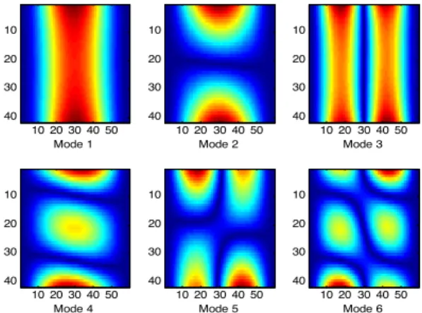
We compute the dynamic behavior of a Cantilever Free Cantilever Free (CFCF) plate on ABAQUS. The modeshapes (eigen vectors) are obtained using a standard eigenvalue solver.The figure 1 plots the 6 first mode shapes.
Mode 1 10 20 30 40 50 10 20 30 40 Mode 2 10 20 30 40 50 10 20 30 40 Mode 3 10 20 30 40 50 10 20 30 40 Mode 4 10 20 30 40 50 10 20 30 40 Mode 5 10 20 30 40 50 10 20 30 40 Mode 6 10 20 30 40 50 10 20 30 40
The nodal lines are obtained by thresholding (displacement close to zero). For each modeshapes we can save nodal lines in a bitmap file (image) for further analysis with image processing tools.
Using a classical EFD algorithm (Figure 3), contours are extracted from the nodal lines data using IP thresholding. From the complex curve, we compute Normalized Fourier Transform, then Fourier Descriptors and finally we are able to reconstruct each mode shape. One drawback of the method is that the image resolution should be enhanced (from 40 by 50 pixels to 200 by 250 pixels, so the resolution is increased by a factor 5 by splines interpolation). Retrieval of the original modeshape can accurately be obtained by the inverse Fourier transform (Figure 3b).
Fig. 2. Elliptic Fourier descriptor are used to reconstruct mode 2 (a) based on 50 Fourier descriptors (d).
Good approximation may reasonably be achieved by retaining only a small number of high energy terms (50 terms). We can see clearly the approximation is enhanced with number of Fourier Descriptors (Figure 4).
4. Application in damage detection
The MAC is used to analyse the correlation between the undamaged plate mode shapes with each other, the following results are obtained (Figure 4).
Nodal Line MAC
U n d a m a g e d P l a t e M o d e s h a p e s
Undamaged Plate Mode Shapes
2 4 6 8 10 12 14 16 18 2 4 6 8 10 12 14 16 18 0 0.1 0.2 0.3 0.4 0.5 0.6 0.7 0.8 0.9 1 Mode 7 10 20 30 40 50 10 20 30 40 Mode 8 10 20 30 40 50 10 20 30 40 Mode 9 10 20 30 40 50 10 20 30 40 Mode 10 10 20 30 40 50 10 20 30 40 Mode 11 10 20 30 40 50 10 20 30 40 Mode 12 10 20 30 40 50 10 20 30 40 Mode 13 10 20 30 40 50 10 20 30 40 Mode 14 10 20 30 40 50 10 20 30 40 Mode 15 10 20 30 40 50 10 20 30 40 Mode 16 10 20 30 40 50 10 20 30 40 Mode 17 10 20 30 40 50 10 20 30 40 Mode 18 10 20 30 40 50 10 20 30 40
Fig. 4. MAC exhibits high similarities (>0.7) betweens mode 10 and 15 (red circle), but comparing mode 10 and 15 we can easily see the difference in the center of the plate
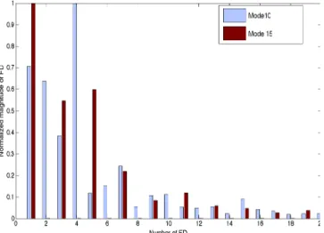
From the MAC results on a simple plate we can observe high similarities between mode 10 and 15 for example (so a coefficient close to 0.7 in the MAC matrix in figure 4). But just comparing FD of these two modes (Figure 5), we can see that important dissimilarities exist. We can also conclude that reconstruction from FD can help to have “local” information of dissimilarities.
Fig. 5. Dissimiliraties can be seen between mode 10 and 15 comparing relative amplitude of Fourier Descriptors
An advanced criteria “correlation of Fourier Descriptor” adapted from correlation of Zernike moment [22-24] should be developed to distinguish close modes using the advantage of comparing at different levels of approximation (From Fourier to Wavelets Descriptors).
Changes in modal parameters (frequency, damping, mode shapes) are commonly used in SHM to detect, localize and identify damages in structures. FRF updating process can help to localize damages [25] but modeshapes are often difficult to use as a tool for localization of damages. In fact, direct comparison of modeshapes of damaged and undamaged plate gives no reliable information about the damage location because many false damages can appear in the map of absolute value of difference of 2 states of modeshapes (damaged, undammaged).
This method will help us to select “interesting modes” in the entire modal basis. The question is: How do we classify them? J Just in selecting modes with the lowest correlation using a mixed indicator. This indicator is just the combination of coefficient of correlation (R) and slope of the polynomial regression (order 1) between two sets of FD (state 1, undamaged, state 2, damaged) with equal weights).
For Finite Element Analysis with ABAQUS we use following dimension and properties:
Plate dimension are 236 x 291 mm, and material properties are close to T700/M21 (laminate composites):
density =1550kg/m3, E1=110.3GPa, E2=E3=7.69GPa, G12=G13=4.75GPa, G23=2.746GPa.
The delamination is localised on the right down part of the plate. We then compute eigenvalues and eigenmodes (modal frequencies and modeshapes) in the [0-2030Hz] frequency bandwidth (15 modes).
Experimentaly modeshapes are commonly estimated from the residues obtained by curve fitting from set of FRFs [12]. In a first approach, comparing all the modeshapes between the two states gives lots of false damage. Then we compute the MAC between state 1 and 2 (Figure 6). We can not conclude about the damage existence and location only using this result (very close from the MAC using only undammaged case on Figure 4).
Fig. 6. Modal Assurance Criteria (MAC) of modeshapes of undamaged plate Vs damaged plate gives no information about the damage location
In a second approach we compare FD of the 15 modeshapes between the 2 states (undammaged, damaged). It also seems to have high correlation between the 2 cases (Figure 7).
Fig. 7 Comparison of Fourier Descriptors of mode 9 for undamaged and damaged cases : on top regression which allows to establish indicators to classify interesting mode shapes
It is interesting to note that the results obtained from classification from R and slope are slightly different (Mode 9 is always the most dissimilar), so we decide to average the influence of these two indicators by creating an indicator which give the same weight to R and slope (Figure 8). It aims at quantifying the “local dissimilarities” of the modeshapes.
Fig. 8 Mixed indicators versus modes, high changes of this indicator permits to see the influence of damage on the nodal line changes. In red, extracted mode shapes for damage localization using lower values of the mixed indicator.
The mapping of a potential damage zone (MD) is then created by a weighted indicator based on the absolute difference between selected modeshapes
!
U
statemod e(x, y)
(step 2 is damaged case, step 1 is undamaged case) taking into account only dissimilar modes in the modal basis (in fact just a thresholding using lower values of the mixed indicator In fact even if each difference localizes the damage by a peak, it exists in every difference false damages (with lower values). So MD has been developed to intersect the location where changes are high and then, the more modes have this change, the more MD is high (Figure 9).!
MD(x, y) = abs(U
92
(x, y) " U
91(x, y))
!
abs(U
52(x, y) " U
51(x, y))
!
abs(U
132(x, y) " U
131(x, y))
(6)Fig. 9. Difference between selected modeshapes (5,9,13). Top mode 9 only, middle combination of mode 5,9, down combination of mode 5,9,13. Classifying most interesting modes permits to reduce influence of false damages.
6. Conclusion
Shape Descriptors show the desirable properties of computational efficiency and ease of image reconstruction using a small number of SD terms. The Elliptic Fourier Descriptors are more general and very effective at extracting mode-shape features by virtue of their sinusoidal patterns. Nodal lines are able to characterize modeshapes very easily. We can wonder if experimentally, is it more convenient (or reliable) to measure displacement or to measure nodal line (null displacement)? Finally, we also validated our method on a CFCF plate demonstrating the quality of advanced for both modeshapes tracking and damage localisation. Futur works will focus on wavelets decomposition as enhanced feature descriptors.
Acknowledgments
This research was fund by EPICEA project (SAPES composites).
References
[1] Doebling SW, Farrar CR, Prime MB. A summary review of vibration-based damage identification methods. Shock and Vibration Digest, 30, 91-105, 1998.
[2] Yan YJ, Cheng L, Wu ZY, Yam LH. Development in vibration-based structural damage detection technique, Mechanical Systems and Signal Processing, 21, 2198-2211, 2007.
[3] E.P. Carden EP, P. Fanning P. Vibration based condition monitoring: A review, Structural Health Monitoring, 3(4), 355– 377, 2004.
[4] Khoo LM, Mantena PR, Jadhav P. Structural damage assessment using vibration modal analysis. Structural Health Monitoring, 3(2), 177-194, 2004.
[5] Gadelrab RM. The effect of delamination on the natural frequencies of a laminated composite beam. Journal of Sound and Vibration, 197(3), 283-292, 1996.
[6] Yam LH, Cheng L. Damage detection of composite structures using dynamic analysis. Key Engineering Materials, 295-296, 33-39, 2005.
[7] Shahdin A, Morlier J, Gourinat Y. Correlating low energy impact damage with changes in modal parameters: A preliminary study on composite beams. Structural Health Monitoring 8(6), 523-536, 2009.
[8] Stubbs N., Park, S., and Sikorski Optimal sensor placement for mode shapes via Shannon's sampling theorem. Microcomputers in civil engineering , 11, 411-419, 1996.
[9] Schulz M.J., Naser A.S., Thyagarajan S.K., Mickens T., and Pai P.F. Structural Health Monitoring Using Frequency Response Functions and Sparse Measurements, Proceedings of the International Modal Analysis Conference, 760-766, 1998.
[10] Sazonov E., Klinkhachorn P., Optimal spatial sampling interval for damage detection by curvature or strain energy mode shapes, Journal of Sound and Vibration 285, 783-801, 2005.
[11] Morlier J., Bos F., Castera P., Diagnosis of a portal frame using advanced signal processing of laser vibrometer data, Journal of Sound and Vibration 297 (2006) 420–431.
[12] D. J. Ewins: Modal Testing: Theory, Practice and Application.
[13] Allemang, Randall J., The Modal Assurance Criterion – Twenty Years of Use and Abuse, University of Cincinnati, Cincinnati, Ohio;
[14] Mark S. Nixon, Alberto S. Aguado “Feature Extraction and Image Processing Second edition” Copyright © 2008 Elsevier.
[15] R. L. Cosgriff, "Identification of Shape," Report No 820-11 of the Ohio State University Research Foundation1960. updating” Journal of Physics: Conference Series, Volume 181, Number 1,2009
[16] C. T. Zahn and R. Z. Roskies. Fourier descriptors for plane closed curves. IEEE Transactions on Computers, 1972. [17] E. Persoon and K.-S. Fu, "Shape discrimination Using Fourier Descriptors," IEEE Transactions on Systems Man and
Cybernetics, vol. SMC-7, pp. 170-179, 1977.
[18] C.-S. Lin and C.-L. Hwang. New Forms of Shape Invariants from Elliptic Fourier Descriptors. Pattern Recognition,20(5):535--545, 1987.
[19] G. H. Granlund, Fourier preprocessing for hand print character recognition IEEE Trans. Comput., vol. C-21,195--201, 1972.
[20] F.P. Kuhl and Ch.R. Giardina, Elliptic Fourier Features of a Closed Contour, CGIP 18, 236-258 (1982)
[21] O. Trier and A. Jain and T. Taxt, Feature extraction methods for character recognition - A survey. Pattern Recognition 29, pp. 641-662, 1996.
[22] Weizhuo Wang, John E. Mottershead, Cristinel Mares, Mode-shape recognition and finite element model updating using the Zernike moment descriptor, Mechanical Systems and Signal Processing, Volume 23, Issue 7, October 2009, Pages 2088-2112
[23]Weizhuo Wang, John E Mottershead, Cristinel Mares, Vibration mode shape recognition using image processing, Journal of Sound and Vibration, Volume 326, Issues 3-5, 9 October 2009, Pages 909-938
[24] Weizhuo Wang, John E Mottershead, and Cristinel Mares, “Shape descriptors for mode-shape recognition and model [25] A. Shahdin, J. Morlier, H. Niemann, and Y. Gourinat, Correlating low energy impact damage with changes in modal