HAL Id: hal-00443799
https://hal.archives-ouvertes.fr/hal-00443799
Submitted on 4 Jan 2010
HAL is a multi-disciplinary open access
archive for the deposit and dissemination of
sci-entific research documents, whether they are
pub-lished or not. The documents may come from
teaching and research institutions in France or
abroad, or from public or private research centers.
L’archive ouverte pluridisciplinaire HAL, est
destinée au dépôt et à la diffusion de documents
scientifiques de niveau recherche, publiés ou non,
émanant des établissements d’enseignement et de
recherche français ou étrangers, des laboratoires
publics ou privés.
A distributed memory multiLevel fast physical optics
algorithm
Christian Parrot, Daniel Millot, Christine Letrou, Amir Boag
To cite this version:
Christian Parrot, Daniel Millot, Christine Letrou, Amir Boag. A distributed memory multiLevel fast
physical optics algorithm. EuCAP 2009 : 3rd European Conference on Antennas and Propagation,
Mar 2009, Berlin, Germany. pp.141-144. �hal-00443799�
A Distributed Memory
Multilevel Fast Physical Optics Algorithm
Christian Parrot
#1, Daniel Millot
#2, Christine Letrou
#3, Amir Boag
∗43Lab. SAMOVAR (UMR CNRS 5157) #Institut TELECOM SudParis
9 rue Charles Fourier, 91011 Evry Cedex, France
1
[email protected], [email protected], [email protected]
∗School of Electrical Engineering, Tel Aviv University
Tel Aviv 69978, Israel
4
Abstract— The MultiLevel fast Physical Optics (MLPO) algo-rithm attains a computational complexity comparable to that of the Fast Fourier Transform (FFT) based techniques by using hier-archical domain decomposition and phase compensated interpo-lation approach. In this communication we present an optimized distributed memory algorithm, obtained by partitioning not only the radiating aperture but also the grid of far field directions. Such a scheme leads to improved speed and reduced memory requirements. The performance of the proposed approach is evaluated in terms of load balance and communication cost, and tested in the context of very large antenna problems.
I. INTRODUCTION
Multilevel Physical Optics (MLPO) algorithms aim at the analysis of very large antennas or scattering problems [1], [2], [3]. MLPO is based on a recursive decomposition of the arbi-trary shaped radiating aperture into sub-apertures, and exploits the sampling properties of the far fields [4]. The multilevel algorithm comprises two main steps: first, computation of the radiation patterns of all sub-apertures of the finest level over a very coarse angular grid; second, multilevel aggregation of the radiation patterns of neighboring sub-apertures into the final pattern of the whole aperture via a phase compensated interpolation. The multilevel algorithm attains computational complexity comparable to that of the FFT based techniques while avoiding their limitations. The algorithm has been tested and its theoretical computational efficiency has been assessed through sequential codes analyzing lens and reflector antennas in the frequency domain.
Based on the message passing approach, initial paralleliza-tion of the MLPO sequential codes has led to significant speedups. However, originally implemented partitioning only among the sub-apertures imposes severe limitations on the efficiency of the MLPO parallelization scheme in terms of both the computational time and memory requirements. Following the same path as the previous works on distributed memory MultiLevel Fast Multipole Algorithms (MLFMA) [5], we address this problem by partitioning not only among sub-apertures but also among the far field directions. Our aim in this work is to propose such a ”shared” scheme and to take
advantage of the MLPO algorithm specific features to optimize communication costs within this parallelization paradigm.
II. MLPOALGORITHM
MLPO applies to multi-reflector configurations [6], and even to cases where non-linear currents occur along disconti-nuities of the reflector surface [7], but for the sake of simplicity we consider in this outline an antenna comprising a feed and a single perfectly conducting reflector S. Distribution of the electromagnetic field produced by the feed over the reflector (Ef(rs), Hf
(rs)), rs∈S, is assumed to be known.
The radiation pattern U(θ, φ) is defined via the far field E(r) as
U(θ, φ) = 4πrejkrE(r) (1) where(r, θ, φ) are the spherical coordinates of the observation point r andk the wavenumber, k = 2πf /c, c being the speed of light andf the frequency. Harmonic time dependence ejωt
, ω = 2πf , is assumed and suppressed.
The radiation pattern is computed as an integral transform of the field over the reflector surface:
U(θ, φ) = jkbr × Z S2ηbr×(b ns×Hf(rs))ejkbr.r s ds (2) b
ns being a unit vector outward normal to S at point rs, b
r(θ, φ) = (sin θ cos φ, sin θ sin φ, cos θ) the unit vector in the direction of observation, andη the free space wave impedance. The MLPO algorithm relies on the sampling theorem ex-posed in [4]. This theorem states that the far field pattern radi-ated by a source distribution of large electrical sizeN = kR, with R the radius of the smallest sphere circumscribing the distribution, is asymptotically (with largeN ) ”fully described” by its samples in a number of directions proportional toN2in
a coordinate system with origin at the center of the smallest circumscribing sphere. This choice of coordinate system origin is of utmost importance as it guarantees minimum phase varia-tion of the radiated field, hence interpolavaria-tion with a prescribed accuracy, for a given sampling rate. In the following, we shall
refer to the center of the smallest sphere circumscribing a given radiating surface as the radiating surface ”center”.
Considering an antenna with electrical size N , the complexity of the far field radiation pattern computation by a classical Physical Optics (PO) algorithm is O(N4). With
the MLPO algorithm, the complexity of the same pattern computation is reduced toO(N2log N ), analog to that of the
FFT algorithm [2].
As a preprocessing step of the multilevel algorithm, a hier-archical domain decomposition subdivides the whole radiating aperture (levelL = 0) into successively smaller sub-domains until the finest level L = M is reached, where sub-domains become roughly a wavelength in linear size. At each levelL < M , every domain is subdivided into four ”children” sub-domains with linear dimensions reduced roughly by a factor of two. In the following, this reduction will be performed by a binary subdivision scheme along each variable describing the radiating aperture.
After this preprocessing step, the MLPO computational sequence starts with the computation of the radiation patterns of sub-domains at levelM . These patterns are obtained by PO surface integrals of the form of (2) involving a limited number of quadrature points on the surface, due to the small size of the sub-domains. For edge sub-domains, Physical Theory of Diffraction (PTD) line integrals can be performed along the reflector edge and the result added to the surface integral [8]. The size of radiation patterns at level M is limited, owing to the sampling theorem, if they are computed in coordinate systems with a different origin for each sub-domain, taken at the center of the sub-domain circumscribing sphere.
The following steps of the algorithm involve successive aggregation of radiation patterns of neighboring sub-apertures, from levelL = M to 1. According to the previously described subdivision scheme, the electrical size for sub-domains at level L, denoted by NL, is approximately multiplied by 2 at each
aggregation level, and the number of far field directions in the patterns must consequently be increased fourfold. Patterns are computed over uniform cartesian grids of angles(θL
m; φLn)
definingPθ(L) × Pφ(L) directions at level L. The aggregation
of the patterns of four level L sub-domains, ”children” of the same level (L − 1) ”parent” sub-domain, first involves interpolation of the ”children” sub-domain patterns, yielding patterns with lengths Pθ(L − 1) = 2Pθ(L) and Pφ(L −
1) = 2Pφ(L) along θ and φ for all level L sub-domains.
These interpolated level L patterns are defined in coordinate systems with their origins at the ”center” of each level L sub-domain. For each group of four level L sub-domains with the same parent at level (L − 1), these patterns must however be expressed in a common coordinate system before their aggregation. The origin of the coordinate system is thus translated to the ”center” of their parent sub-domain. Origin translation is easily performed by ”phase compensation”.
Finally, performing ”interpolation - origin translation - ag-gregation” repeatedly from level L = M to level L = 1 we obtain a sufficiently sampled pattern for the whole reflector
surface (levelL = 0 domain).
III. ANALYSIS OFMLPOSPECIFICITY IN VIEW OF PARALLELIZATION
At the finest level of decomposition L = M , the indepen-dent computation of a large number of small radiation patterns can be distributed among the processing units. The following steps of the algorithm involve aggregation of radiation patterns of neighboring sub-apertures. After n aggregation steps, the number of far field directions for each sub-domain is mul-tiplied by 4n. For a large radiating surface, this might lead
to a bottleneck in terms of memory requirement per node, if the grid of far field directions is not distributed. In addition, when the number of radiation patterns becomes smaller than the number of processing units, the computational work on each radiation pattern should be distributed to fully exploit the parallelization potential speedup.
It must be stressed however that in the MLPO algorithm the total memory requirements remain approximately the same whatever the levelL: at any aggregation step, in a binary sub-division algorithm, the number of sub-domains is divided by four while the number of far field directions in the observation grid is approximately multiplied by four. Optimal distribution of computational tasks should lead then to an approximately constant memory requirement at each processing unit, through the successive aggregation levels. Ideally, this requirement should be close to the maximum available memory at a given node, in order to minimize the communication cost.
IV. DISTRIBUTED MEMORYMLPOALGORITHM
In the proposed algorithm, sub-apertures are at first dis-tributed according to geometrical proximity, so that at the high levels (integration and first aggregation steps) no communica-tion is involved in the aggregacommunica-tion of their patterns. At each transition between levels, four patterns are aggregated after an interpolation which increases their length fourfold, according to the algorithm described in Part II. When radiation patterns become too large for the available memory or the number of patterns roughly equal to the number of processing units, each pattern is cut into four parts which are distributed among four nodes before interpolation. Hence, considering four patterns to be aggregated, i.e. patterns of sub-domains sharing the same ”parent”, and the four processing units where these initial patterns have been computed, three quarters of each pattern have to be transmitted by each processing unit, one quarter to each of the three other processing units.
The communication process at a given level L can then be described as follows. Let us consider four processing units (PUs) which have respectively computed the field radiated by four neighboringL-level domains (i.e. ”children” sub-domains of the same ”parent”), on a grid of PL far field
directions.
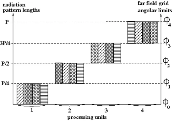
1) Each PU splits its level L radiation pattern into four sub-patterns of equal lengthPL/4 (corresponding to a
Fig. 1. L-level pattern lengths and angular limits along φ (far field directions).
2) Each PU performs an immediate send of the sub-patterns of length PL/4 to the three PUs which share the same
observation grid for neighboring sub-domains, its ”level L associates”.
3) Each PU performs a blocking receive of the sub-patterns sent by its ”levelL associates”.
At the end of this communication process, instead of having in their memory four sub-patterns for the same sub-domain, each of the PUs uses the same memory allocation to store four patterns of neighboring sub-domains on the same ob-servation sub-grid. This is illustrated in Figures 1 and 2, where the different fillings correspond to patterns radiated by four neighboring sub-domains, and where the far field pattern partitioning is supposed to be performed along theφ angular variable (for the simplicity of visual representation). It must be noted that in the course of this communication procedure, the maximum number of pattern values to be stored at a given PU is 2PL. Also, at a given level, a PU communicates only
with three other PUs, and the size of the data to be sent (resp. received) remains constant, equal to3PL/4 pattern values.
Fig. 2. Pattern lengths and angular limits along φ after the communication process and before interpolation-aggregation.
Once the levelL communications are over at a given node, the usual aggregation operations are performed (”interpola-tion - origin transla(”interpola-tion - aggrega(”interpola-tion”), yielding the level
(L − 1) pattern of the ”parent” sub-domain. The size of the initial patterns being PL/4, interpolation leads to a pattern
of size PL. Successive interpolations and summations of the
four initial patterns do not require more memory allocation than3PL pattern values.
After aggregation, the memory requirement at a given node is again for a single pattern defined in PL directions, hence
PL−1= PL. In this way, memory requirement per processing
unit is kept the same through successive aggregation levels. When the final L = 0 level is reached each PU stores a radiation pattern of the whole aperture on a partial observation grid. All together, the patterns stored at the different nodes represent the full 3D radiation pattern of the antenna.
V. FIRST NUMERICAL TESTS
We consider a centered reflector antenna system as depicted in Fig. 3, with reflector diameterDm= 20λ and f /Dm= 0.8
as a scale s = 1 configuration. The linear electrical size of the scale 1 antenna is No ∼ 62.8. Scaled models, with
increasing scales ranging from s = 2 to 8 (N = sNo), are
used to establish preliminary results regarding computation time and memory requirements. We take a Huygens source as the primary source feed. Physical Theory of Diffraction (PTD) contributions are added in the form of line integrals of Incremental Length Diffraction Currents along the reflector edge when computing the radiation patterns of the smallest sub-domains at the highest level. In the present work, the formulation used for ILDCs is taken from [8].
Fig. 3. Geometry of the reflector antenna with its circumscribing sphere.
The number of levels in the multilevel algorithm is automat-ically determined so as to reach roughly a wavelength size for sub-domains at the highest level. For the scale 1 antenna, the number of levels is M = 4, and this number is increased by 1 each time the scale is multiplied by 2. The MLPO algorithm computes the 3D radiation pattern of the antenna on the total solid angle. It is implemented with relatively high oversampling. At the highest level (small sub-domains) the number ofθ samples is Pθ(M ) = 28, the number of φ samples
isPφ(L) = 38. These pattern lengths include four extra-points
required at end points by the centered cubic interpolation scheme used to interpolate patterns at successive levels. The
surface integration on the levelM sub-domains is performed with an eight point Gaussian quadrature routine along each integration variable defining the surface (here, polar variables describing the reflector projection in a plane perpendicular to the antenna symmetry axis). Figures 4 and 5 present half plane cuts of the scale 1 antenna radiation pattern.
Fig. 4. E-plane amplitude pattern computed by MLPO (to be compared with Fig. 4a in [8]).
Fig. 5. φ = 45 deg cross-polar amplitude pattern computed by MLPO (to be compared with Fig. 4c in [8]).
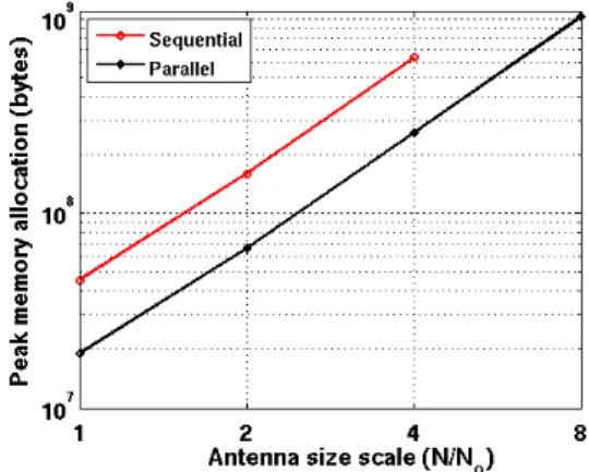
A parallel version based on the message passing approach has been implemented on a grid of four PCs, and memory checks have been performed, comparing sequential and paral-lel executions. Due to the small number of PUs, distribution of the observation grid among the processing units is only performed at the last level (L = 1, with transition to L = 0). The level M to 2 computations are performed independently by each PU, which computes the radiation pattern of a level 1 sub-domain. Figure 6 compares memory requirements for computations performed with the sequential and parallel implementations of the previously described MLPO algorithm, applied to the antenna configurations described above. It must be stressed first that the sequential code runs out of memory in the scale 8 case (on our grid of PCs). The fact that the distributed memory algorithm allows for larger problem computations validates the mixed ”sub-domain and pattern
distribution” approach of the MLPO algorithm presented here. Former ”sub-domain distribution only” approaches lead to memory bottlenecks at even smaller scales than with sequential execution.
For scales amenable to sequential execution, the memory requirements of the parallel MLPO are clearly reduced by an approximately constant factor with respect to the sequential execution memory requirements. This was the expected result, and the fact that this factor remains constant with increased scale illustrates the validity of our pattern distribution scheme.
Fig. 6. Peak memory requirements for sequential and parallel executions (4 PU), versus the linear electrical size of the problem normalized to the initial size No.
Numerical results regarding execution time, communication cost and maximum size of the problem versus available memory per node will be presented at the conference.
REFERENCES
[1] A. Boag and C. Letrou, “Fast radiation pattern evaluation for lens and reflector antennas,” IEEE Trans. Antennas Propagat., vol. 51, pp. 1063– 1068, May 2003.
[2] ——, “Multilevel Fast Physical Optics algorithm for radiation from non-planar apertures,” IEEE Trans. Antennas Propagat., vol. 53, pp. 2064– 2072, June 2005.
[3] A. Boag, “A Fast Physical Optics (FPO) algorithm for high frequency scattering,” IEEE Trans. Antennas Propagat., vol. 52, pp. 197–204, Jan. 2004.
[4] O. Bucci and G. Franceschetti, “On the spatial bandwidth of scattered fields,” IEEE Trans. Antennas Propagat., vol. 35, pp. 1445–1455, Dec. 1987.
[5] S. Velamparambil and W. Chew, “Analysis and performance of a dis-tributed memory multilevel fast multipole algorithm,” IEEE Trans.
An-tennas Propagat., vol. 53, pp. 2719–2727, Aug. 2005.
[6] C. Letrou and A. Boag, “Analysis of very large dual-reflector antennas using multilevel physical optics (MLPO) algorithm,” in ICEAA ’07 :
International Conference on Electromagnetics in Advanced Application (10th edition), September 17-21, Torino, Italy, IEEE, Ed., Piscataway, NJ, USA, 2007, pp. 281 – 282.
[7] A. Shlivinski, C. Letrou, and A. Boag, “Fast time domain physical optics for non linear scattering,” in EuCAP 2007 : The Second European
Conference on Antennas and Propagation , November 11-16, Edinburgh, UK, T. I. of Engineering and Technology, Eds., 2008.
[8] R. Shore and D. Yaghjian, “Application of incremental length diffraction coefficients to calculate the pattern effects of the rim and surface cracks of a reflector antenna,” IEEE Trans. Antennas Propagat., vol. 41, pp. 1–11, Jan. 1993.