HAL Id: hal-01692471
https://hal.archives-ouvertes.fr/hal-01692471
Submitted on 25 Jan 2018
HAL is a multi-disciplinary open access archive for the deposit and dissemination of sci-entific research documents, whether they are pub-lished or not. The documents may come from teaching and research institutions in France or abroad, or from public or private research centers.
L’archive ouverte pluridisciplinaire HAL, est destinée au dépôt et à la diffusion de documents scientifiques de niveau recherche, publiés ou non, émanant des établissements d’enseignement et de recherche français ou étrangers, des laboratoires publics ou privés.
A new approach of studying mixed gas hydrates
involving propane at non-equilibrium conditions and
final state: An experimental study and modeling
Saheb Maghsoodloo Babakhani, Baptiste Bouillot, Jérôme Douzet, Son
Ho-Van, Jean-Michel Herri
To cite this version:
Saheb Maghsoodloo Babakhani, Baptiste Bouillot, Jérôme Douzet, Son Ho-Van, Jean-Michel Herri. A new approach of studying mixed gas hydrates involving propane at non-equilibrium conditions and final state: An experimental study and modeling. Chemical Engineering Science, Elsevier, 2018, 179, pp.150 à 160. �10.1016/j.ces.2018.01.017�. �hal-01692471�
A new approach of studying mixed gas hydrates involving propane
at non-equilibrium conditions and final state: An experimental study
and modeling
Maghsoodloo Babakhani S.*, Bouillot B., Douzet J., Ho-Van S., Herri J.M.
Ecole des Mines de Saint-Etienne, SPIN, CNRS 5307, LGF, F-42023 Saint-Etienne, France * Corresponding author: saheb.m@emse.fr
Abstract
Metastable clathrate hydrates are a promising energy source in the shallow geosphere and present challenges in flow assurance, energy storage, and carbon capture sequestration. While they have been widely studied, little pertinent data is available for common propane hydrates concerning hydrate phase composition, nor its volume or the amount of converted water. This was the initial motivation for our work. Therefore, with a novel technique, propane hydrate composition and volume were measured dynamically at non-equilibrium conditions over time and at the final states for slow and quick rates of crystallization. Surprisingly, equilibrium pressure, hydrate volume and composition are different according to crystallization rate. The hydrate volume and water conversion in the quick crystallization process were larger. Moreover, at a slow crystallization rate, in a hydrocarbon mixture, enclathration of propane is more considerable and the hydrate crystals appear to be more homogeneous. Furthermore, the hydrate crystallization of a gas mixture is closer to the thermodynamic equilibrium at slow crystallization rates where the impact of kinetics is slight. A new compilation of propane Kihara parameters was presented. Unlike methane, ethane and carbon dioxide, for propane we strongly recommend two Kihara parameters, one for pure and the other for mixtures of propane. A thermodynamic model based on classical van der Waals and Platteuw model was also used to investigate the effects of kinetics. The simulation results have a satisfactory accordance with the experimental data from literature to predict the hydrate equilibrium pressure. The consequence of this research could have a substantial impact on design calculations in which the assumption of thermodynamic equilibrium are done. For instance, at present there would be excess hydrates volume estimations for pipe-lines, equilibrium conditions in energy storage and transportation or carbon capture sequestration and thus increase expenses or loss of productivity where propane is concerned. Keywords: Clathrate hydrates, crystallization, thermodynamics, non-equilibrium, modeling, flow assurance
1. Introduction
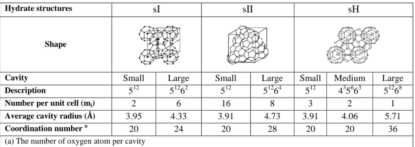
Clathrate hydrates, are solid compounds composed of cages of water with guest “gas molecules” trapped inside (Sloan and Koh, 2007). Based on the number and type of cavities and the gas
molecular arrangements, three different principal structures can be formed: I, II and H. Table 1 briefly details the structures.
Table 1. The differences between the various structures of gas hydrates (Sloan and Koh, 2007)
Hydrate structures sI sII sH
Shape
Cavity Small Large Small Large Small Medium Large
Description 512 51262 512 51264 512 435663 51268
Number per unit cell (mi) 2 6 16 8 3 2 1 Average cavity radius (Å) 3.95 4.33 3.91 4.73 3.91 4.06 5.71
Coordination number a
20 24 20 28 20 20 36
(a) The number of oxygen atom per cavity
Understanding better gas hydrates has been crucial since they can form in oil and gas pipelines and block their flow. Therefore, flow assurance has been a crucial interest of research for decades (Song and Kobayashi, 1982; Dholabhai and Bishnoi, 1994; Chen et al., 2015; Balakin et al., 2016). Recently several new applications for gas hydrates have been investigated, such as gas separation (Linga et al., 2007; Eslamimanesh et al., 2012), CO2 capture (Duc et al., 2007; Herri
and Kwaterski, 2012; Herri et al., 2014; Zhou and Infante Ferreira, 2017), gas storage and transportation (Ogata et al., 2008; Ando et al., 2012; Maghsoodloo Babakhani and Alamdari, 2015), energy resources (Ji et al., 2001; Makogon, 2010; Wang et al., 2015) and even planetary science (Herri and Chassefière, 2012). Hence, it is obvious that studying the thermodynamics and crystallization mechanisms of clathrate hydrates is essential to many scientific domains. There are two important questions. When and how much (Volume) do gas hydrates form?
While gas hydrates of mixed hydrocarbon have been widely studied, still to the best of our knowledge there are few publications involving propane in the literature. Furthermore, two significant parameters: hydrate phase composition and volume, are rarely provided. Therefore, we applied two diverse procedures to furnish our data for propane mixtures.
Furthermore, although several studies can be found that report the final state of equilibrium for gas hydrates, is thermodynamic equilibrium reached? How does the rate of crystallization affect the final state? In addition, several studies already pointed out some discrepancies between experimental results (Eslamimanesh et al., 2013), while others showed the possible mixed hydrate formation under non-equilibrium conditions (Bouillot and Herri, 2017). Consequently, studying the influence of the crystallization rate on the final state of the system in a closed batch reactor was also chosen.
Since gas hydrate experiments can be quite time consuming, developing reliable robust and efficient models is of great importance. In the last section, a thermodynamic model, implementing classic van der Waals and Platteuw model (van der Waals and Platteeuw, 1959) and using Kihara parameters, were utilized. Then, a new set of Kihara parameters for propane were re-fitted and the accuracy of modelling was evaluated for our experiments with benchmarks from literature. Conclusions and some final remarks on possible future work and their significance finish this article.
2. Experimental section
2.1. Experimental set-upTwo almost identical apparatuses were employed, having the same characteristics and specs except for volumes. The first is 2.36 liter, while the second is 2.23L. Both are closed batch reactors equipped with vertical stirrers each with two sets of four blades. The top set of blades is in the gas phase and the bottom set in liquid. The temperature is controlled by a thermal jacket in which is circulated a fluid at constant temperature (ranging from -2 to 20 degrees C.) refrigerated with cryostat HUBERT CC-250. The liquid is injected in the reactor under pressure by using a HPLC pump (JASCO). Temperature is monitored by two Pt100 probes, for gas and liquid phases. An online ROLSI sampler is mounted on the reactor sampling the gas and subsequently sending it into a gas chromatograph (GC Varian model 38002) equipped with a TCD detector and two columns PoraBOND Q and CP-Molsieve. Peak integration is possible with software provided by Varian Galaxie. Another sampling system is used for the liquid phase via a mechanical valve and capillary tube. The liquid is analyzed by ion chromatography. Thus, the volume of the liquid phase can be determined, thanks to an ionic tracer LiNO3. Data acquisition is controlled on a
Figure 1. The schematic of the apparatus
2.2. Experimental procedures
2.2.1. Quick crystallization procedure
Using the same previous procedure as we did on gas hydrates equilibria (Herri et al., 2011; Le Quang et al., 2015), the crystallization occurs at a “high rate” (or at a high initial supersaturation). At first, the reactor is cleaned and vacuumed (for 40-50 minutes). Then, the cell is filled with the prepared gas mixture. Pressure and temperature are measured and the gas composition is checked with GC analysis. Thanks to these measurements, the amount of each gas molecules can be calculated using an appropriate Equation of State (EoS). Then, the cryostat temperature is set to 1°C. A 10 mg/L water mixture of LiNO3 is then prepared and pumped (about 800g) into the
reactor via the aforementioned HPLC. The water is ultrapure water (first category, 18.2 MΩ.cm) and LiNO3 acts as a tracer to monitor the water volume. It does not influence hydrate
equilibrium. An increase of pressure, due to the added volume of liquid, is observed. Then, the batch is stirred at the rate of 400 rpm on both the upper gas and lower liquid sections. After the gas dissolution into the liquid phase, and the induction time, the crystallization begins. Due to the exothermicity of the reaction, a short-term increase of temperature is observed. At this point, it is necessary to wait for equilibrium to be attained (no more changes in temperature or pressure). After equilibrium is reached, a sample of the gas phase is taken and injected into the gas chromatograph to determine the molar composition. A liquid sample is also taken to be analyzed by ionic chromatography (about 2-3mg). Then, the dissociation of the hydrate is begun. Temperature is increased by about 1-2°C, over about 24 hours with a maximum of two days.
Then when second equilibrium is reached, new samples of the fluid phases are taken. Then, the process is iterated until there is no longer a hydrate phase into the reactor. The whole procedure is summarized on Figure 2a.
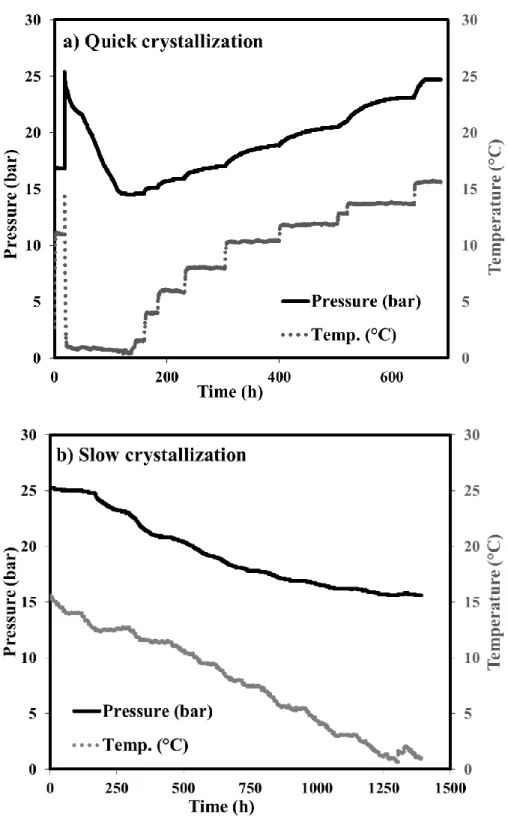
2.2.2. Slow crystallization process
In this procedure, from an initial state of just liquid and gas, the temperature is decreased slowly. Therefore, crystallization starts near the first liquid-hydrate equilibrium temperature. The temperature is then decreased very slowly (0.6°C/day). With each temperature drop of approximately 2 degrees, gas and liquid samples are taken and analyzed by gas-chromatograph and ion-chromatograph, respectively. Our aim is to focus on the thermodynamic equilibrium conditions (ignoring kinetic effects). This is closer to a steady state process. A diagram of this procedure is illustrated in Figure 2b.
Figure 2. Schematic of the experimental procedures: a) Quick crystallization process. b) Slow crystallization process
2.3. Mass balance
The mass balance for each molecule is used to determine the amount of gas molecules in the hydrate phase (𝑛𝑗𝑔):
𝑛𝑗0 = 𝑛𝑗𝐿+ 𝑛𝑗𝐻+ 𝑛𝑗𝑔 (1)
Where j is guest molecule, 0 indicates the initial condition, n is mole number, L, H and g stand for the liquid, hydrate and gas phases, respectively.
Fluid phases are analyzed through GC and ionic chromatography. The amount of gas sampled is really small (about µm3), so it can be neglected. For liquid analysis, at each point, about 2-3 ml of solution is taken. Hence its removal was taken into account at each step when evaluating the actual mass of water and lithium concentration in the solution.
As aforementioned, about 10ppm Li+ was used for each experiment as a tracer. The volume of the water phase can be calculated based on the mass balance of the lithium concentrations:
𝑉𝐿 =𝑉0𝐿[𝐿𝑖0+]
[𝐿𝑖+] (2)
where 𝑉𝐿 is the volume of liquid at equilibrium, 𝑉0𝐿 is the volume of injected solution, 𝐿𝑖0+ the initial concentration of Lithium and 𝐿𝑖+ is the concentration of lithium at equilibrium. The two last parameters can be measured by an ion-chromatograph. Knowing the mass of water in liquid phase, and consequently the mass of water in the hydrate phase, the volume of hydrate at equilibrium can be calculated based on the theoretical density of structures I and II (Sloan and Koh, 2007). In fact, density difference between structures I and II, only based on water molecules (β reference state), is 5 kg/m3
(790 kg/m3 and 785 kg/m3 for structures I and II, respectively). Therefore, if the wrong structure is assumed in the calculations, the error on the calculated hydrate volume is about 0.6%. If both structures are present, this error is even lower. That is why the reliability of the hydrate volume is not really affected by the structure assumption. In fact, ionic chromatography analysis is probably more affected by uncertainties.
It should be noted that for taking samples at each three phase equilibrium condition (V-L-H), we stopped the agitation. Due to difference in density of water and hydrate, hydrate and liquid phases separated; liquid phase at the bottom of reactor and hydrate phase at the top. The sampling tube is located at the bottom of reactor. Furthermore, we saw neither crystals nor turbidity showing presence of crystals in the samples with our naked eyes. Hence, we assumed that hydrate crystals were not sampled with the liquid.
The mole number of each gas in liquid phase can be also determined from gas solubility in water. Note that the effect of LiNO3 is neglected, due to its low solubility in water. Gas solubility is
calculated according to the Henry’s law under the following form (Holder et al., 1980): 𝑛𝑗𝐿 =𝑉𝐿𝜌𝑤0 𝑀𝑤 𝑦𝑖𝜑𝑗𝐺𝑃 𝐾𝐻,𝑗∞𝑒𝑥𝑝(𝑃𝑣𝑗 ∞ 𝑅𝑇 ⁄ ) (3)
where 𝜌𝑤0and 𝑀𝑤 stand for the density and molecular weight of water, respectively, 𝜑𝑗𝐺 fugacity coefficient of gas j, 𝑣𝑗∞ is the partial molar volume of the gas j in the solvent water (𝑣𝑗∞=32 cm3mol-1 (Holder et al., 1980)) and 𝐾𝐻,𝑗∞ is Henry’s constant and can be calculated from the following equation (Holder et al., 1988):
𝐾𝐻,𝑗∞ = exp (𝐴 +𝐵
𝑇) (4)
Table 2. The values of A and B for calculating the Henry’s constants (Holder et al., 1988) Gas A B (K) CO2 14.283146 -2050.3269 N2 17.934347 -1933.3810 CH4 15.872677 -1559.0631 C2H6 18.400368 -2410.4807 C3H8 20.958631 -3109.3918
2.3.2. The gas phase
The composition of gas phase at any state during the course of experiments can be known by gas-chromatograph. Then the mole number of gas at initial state (𝑛𝑗0) and at equilibrium (𝑛
𝑗𝑒𝑞) can be
calculated as following:
𝑛 =𝑍(𝑃,𝑇,𝑦)𝑅𝑇𝑃𝑉𝐺 (5)
where P is pressure, Z is compressibility factor which can be calculated from Soave-Redlich-Kwong equation of state (Danesh, 1998). The gas volume 𝑉𝐺 at equilibrium is:
𝑉𝐺 = 𝑉𝑅− 𝑉𝐿− 𝑉𝐻 (6)
Volumes for the reactor (𝑉𝑅) are 2.23 and 2.36 liter. The two last parameters in equation 6 are
known at each state based on the procedure explained in section 2.3.1.
2.3.3. The hydrate phase
Once the mole number of gas in gas and liquid phases is calculated, then the mole number and composition of each gas in hydrate phase can be calculated by equation 1.
3. Modeling
During the past decades, many researchers have tried to model gas hydrate phenomena based on different approaches, such as K-value method (Wilcox et al., 1941), gas gravity charts (Katz, 1945), statistical and neural networks (Ghavipour et al., 2013; Maghsoodloo Babakhani et al., 2015) and thermodynamic models (van der Waals and Platteeuw, 1959; Parrish and Prausnitz, 1972; Javanmardi et al., 1998; Bouillot and Herri, 2015). Nevertheless, the most reliable approach is thermodynamic model and moreover, it has fewer limitations compared to other approaches.
Thermodynamic equilibrium can be described by the equality of chemical potential at each phase. In the case of gas hydrates, the equality of chemical potential of water in liquid phase (µ𝑊𝐿 ) and
hydrate phase (µ𝑊𝐻) can be taken into account:
µ𝑊𝐿 = µ 𝑊
𝐻 (7)
van der Waals and Platteuw model was used in this paper to describe the gas hydrate equilibria (van der Waals and Platteeuw, 1959). Some of the assumptions required for this model should be noted. First, cavities are postulated to be spherical and only a single gas molecule can be trapped in one cavity. Second, a pair potential function of gas-molecule is used to describe the interaction between the guest molecule and water. Third, there is no interaction among the guest molecules and additionally these guest molecules do not deform the cavities. Van der Waals and Platteuw model also includes a hypothetical phase β which corresponds to the empty cavities in hydrate phase. So the equation 7 can be re-written as the equality of difference between chemical potential of water in liquid phase and β phase (∆𝜇𝑊𝐿−𝛽) and the difference between chemical potential of water in hydrate phase and β phase (∆𝜇𝑊𝐻−𝛽).
∆𝜇𝑊𝐿−𝛽 = ∆𝜇𝑊𝐻−𝛽 (8)
3.1. Liquid phase
In the left hand side of equation 8, the difference in chemical potential of water in liquid phase and β phase, can be described by classical thermodynamics using Gibbs-Duhem equation of state as following: ∆𝜇𝑊𝐿−𝛽 = 𝑇∆𝜇𝑊 𝐿−𝛽| 𝑇0𝑃0 𝑇0 − 𝑇 ∫ ∆ℎ𝑊,𝑚𝐿−𝛽| 𝑃0 𝑇2 𝑑𝑇 𝑇 𝑇0 + ∫ ∆𝑣𝑊,𝑚𝐿−𝛽|𝑇𝑑𝑃 𝑃 𝑃0 − 𝑅𝑇𝑙𝑛𝑎𝑊𝐿 |𝑇,𝑃 (9)
Where T0=273.15K and P0=0 bar are the reference temperature and pressure, respectively. 𝑎𝑊𝐿 is the water activity in liquid phase. It can be described by the activity coefficient and as we used pure water without any additives, with an adequate approximation, the water activity can be expressed by 𝑎𝑊𝐿 = 𝑥𝑊𝐿 . ∆𝑣𝑊,𝑚𝐿−𝛽|
𝑇is the molar volume difference between the liquid phase and β
phase and von Stackelberg measured its value by X-ray diffraction (Stackelberg and Müller, 1951). ∆ℎ𝑊,𝑚𝐿−𝛽|
𝑃0 is the difference in enthalpy between the liquid phase and β phase and it can be
expressed by using the classical thermodynamics (Sloan and Koh, 2007): ∆ℎ𝑊,𝑚𝐿−𝛽| 𝑃0 = ∆ℎ𝑊,𝑚 𝐿−𝛽| 𝑃0𝑇0+ ∫ ∆𝐶𝑝,𝑤 𝐿−𝛽| 𝑃0𝑑𝑇 𝑇 𝑇0 (10)
By assuming linear dependence of ∆𝐶𝑝,𝑤𝐿−𝛽|
∆𝐶𝑝,𝑤𝐿−𝛽| 𝑃0 = ∆𝐶𝑝,𝑤 𝐿−𝛽| 𝑃0𝑇0 + 𝑏𝑃,𝑊 𝐿−𝛽(𝑇 − 𝑇0) (11) ∆ℎ𝑊,𝑚𝐿−𝛽| 𝑃0𝑇0and ∆𝜇𝑊 𝐿−𝛽|
𝑇0𝑃0 are the thermodynamic properties with various values corresponding
to each author. Based on a previous study of our team, by comparing several thermodynamics values, we concluded that the values from Handa and Tse are the best set to use for modeling of gas hydrates (Herri et al., 2011). The values of all reference and thermodynamic properties are in Tables 3 & 4.
Table 3. Reference properties of the two different structures of gas hydrates (Sloan and Koh, 2007)
Parameters (units) Structure I Structure II
∆𝐶𝑝,𝑤𝐿−𝛽| 𝑃0𝑇0 (J/mol/K) -38.12 -38.12 𝑏𝑃,𝑊𝐿−𝛽 (J/mol/K2) 0.141 0.141 ∆𝑣𝑊,𝑚𝐿−𝛽| 𝑇0𝑃0 (10 -6 m3/mol) 4.5959 4.99644
Table 4. Thermodynamic properties of gas hydrates for structures I and II (Handa and Tse, 1986)
Structure I Structure II ∆𝜇𝑊𝐿−𝛽| 𝑇0𝑃0 ∆ℎ𝑊,𝑚 𝐿−𝛽| 𝑃0𝑇0 ∆𝜇𝑊 𝐿−𝛽| 𝑇0𝑃0 ∆ℎ𝑊,𝑚 𝐿−𝛽| 𝑃0𝑇0 1287 934 1068 764
Hence by re-writing the equation 9, the difference in chemical potential of water in liquid and β phases can be expressed by following equation:
∆𝜇𝑊𝐿−𝛽 = 𝑇∆𝜇𝑊 𝐿−𝛽| 𝑇0𝑃0 𝑇0 + (𝑏𝑃,𝑊𝐿−𝛽𝑇0− ∆𝐶𝑝,𝑤𝐿−𝛽|𝑃0𝑇0) − 𝑇𝑙𝑛𝑇𝑇0+ 1 2𝑏𝑃,𝑊 𝐿−𝛽𝑇(𝑇 − 𝑇0) + (∆ℎ 𝑊,𝑚 𝐿−𝛽| 𝑃0𝑇0+ 𝑇0(𝑏 𝑃,𝑊𝐿−𝛽𝑇0− ∆𝐶𝑝,𝑤𝐿−𝛽| 𝑃0𝑇0) − 1 2𝑏𝑃,𝑊 𝐿−𝛽𝑇02 ) (1 −𝑇𝑇0) + ∆𝑣𝑊,𝑚𝐿−𝛽| 𝑇0(𝑃 − 𝑃 0) − 𝑅𝑇𝑙𝑛𝑥 𝑊𝐿 (12) 3.2. Hydrate phase
The right hand side of equation 8 is the difference between chemical potential of water in hydrate phase and β phase (∆𝜇𝑊𝐻−𝛽) and it can be described by statistical thermodynamic functions. In the model of van der Waals and Platteuw, this parameter was expressed based on the occupancy factor of the guest molecule i in cavity j (𝜃𝑗𝑖).
where 𝑣𝑖 is the number of cavities type i per mole of water. The occupancy factor can be described by considering the analogy among gas adsorption in the three dimensional hydrate structures and two-dimensional Langmuir adsorption (Sloan and Koh, 2007).
𝜃𝑗𝑖 = 𝐶𝑗𝑖𝑓𝑗(𝑇,𝑃)
1+∑ 𝐶𝑗 𝑗𝑖𝑓𝑗(𝑇,𝑃) (14)
where 𝑓𝑗(𝑇, 𝑃) is the fugacity of guest molecule j at a desired temperature and pressure. The value of fugacity in the gas phase can be calculated based on Soave-Redlich-Kwong equation of state, because at equilibrium condition the equality of fugacity in gas, liquid and hydrate phases is taken into account. By re-writing the equation 13:
∆𝜇𝑊𝐻−𝛽 = 𝑅𝑇 ∑ 𝑣𝑖 𝑖ln(1 − ∑ 𝐶𝑗 𝑗𝑖𝑓𝑗(𝑇, 𝑃)) (15)
In this equation, 𝐶𝑗𝑖 is the Langmuir constant of guest molecule j in the cavity type i and it is defined as the interaction potential between the trapped guest molecules and the surrounding water molecules and can be expressed by a spherical symmetrical potential as follows:
𝐶𝑗𝑖 =4𝜋 𝑘𝑇∫ exp(− 𝑤(𝑟) 𝑘𝑇 )𝑟 2𝑑𝑟 ∞ 0 (16)
where w(r) is the interaction potential between the guest molecule and the cavity based on the distance between the gas and water molecules in the structure (r). van der Waals and Platteeuw (van der Waals and Platteeuw, 1959) and Parrish and Prausnitz (Parrish and Prausnitz, 1972) proposed some models to determine the interaction potential. McKoy and Sinagoglu reported that so-called Kihara parameters are the most reliable model to calculate the interaction potential (McKoy and Sinanoğlu, 1963). Hence w(r) can be defined as following:
𝑤(𝑟) = 2𝑧𝜀 [𝑅𝜎1112𝑟(∆10+𝑎 𝑅∆11) − 𝜎6 𝑅5𝑟(∆4+ 𝑎 𝑅∆5)] (17) ∆𝑁= 1 𝑁[(1 − 𝑟 𝑅− 𝑎 𝑅) −𝑁 − (1 +𝑟𝑅−𝑎𝑅)−𝑁] (18)
Parameters𝜀, 𝜎 and a are Kihara parameters and correspond to the maximum attractive potential, distance from the center of cavity and the hard-core radius, respectively. Two of the Kihara parameters are fitted according to the experimental data of pure gas hydrates. The hard-core radius is calculated from viscosity (Tee et al., 1966b) or by values of the second virial coefficient (Sherwood and Prausnitz, 1964) and the radius value for each gas does need to be optimized again. The algorithm for optimal Kihara parameters is depicted in Figure 3.
Figure 3. The algorithm of Kihara parameters optimization
During the past years, we have optimized the set of Kihara parameters for several gases such as CO2, Ar, N2, CH4, C2H6 etc. (Herri et al., 2011, p. 2; Herri and Chassefière, 2012; Le Quang et
al., 2015) and this article provides a set of Kihara parameters for propane in the gas mixtures. The results will be explained in the section 4.2.
All the thermodynamic modelling section and Kihara parameter optimization process have been implemented in our in-house software, GasHyDyn, which helps us to predict equilibrium pressure, gas composition in hydrate phase, as well as optimization of Kihara parameters.
4. Results and discussion
4.1. Experimental results
Two binary mixtures involving propane have been experimentally studied to measure the gas composition in hydrate phase and also the volume of hydrate, not only at final state, but also during the crystallization and at non-equilibrium conditions. For each binary mixture, we also conducted two different experiments to understand better the impact of the rate of crystallization on hydrate formation. To obtain the precious data, for each binary mixture, initial conditions must be the same. Table 5 lays out the initial condition of experiments. Figure 4 shows the change over
time of pressure and temperature for the mixtures of methane-propane and ethane-propane according to the different crystallization rates.
Table 5. The initial conditions for performing the experiments
Type of experiment
Gas composition (%) Reactor volume (L) Water injected (g) Initial pressure (bar) Initial temperature (°C) CH4 C2H6 C3H8 Quick crys. 86.14 - 13.86 2.36 801.4 25.3 14.9 Slow crys. 87.56 - 12.44 2.36 802.4 25.2 15.3 Quick crys. - 81.09 18.91 2.23 798.6 19.1 10.5 Slow crys. - 81.72 18.28 2.23 799.1 18.7 10.4 Uncertainties 0.01 0.01 0.1 0.1 0.02
Figure 4. The evolution of pressure and temperature during the course of experiments for methane-propane mixture: a) Quick crystallization process and b) Slow crystallization process
As seen in Figure 4, for the quick crystallization process, after the injection of gas and solution, the temperature was rapidly decreased. Once gas hydrate formation was completed, the temperature was increased incrementally and at each two day step gas and liquid samples were taken for analysis. It took about one month to perform this experiment. Contrarily, for the slow crystallization process with the same initial condition, instead of decreasing temperature rapidly, we decreased temperature very slowly and at each step gas and liquid samples were taken. This experiment took longer, more than two months to finish. The results of these two experiments for all the mixtures are detailed in the table 6. Additionally, table 6 provides all the information about non-equilibrium condition during crystallization, as well as the final state.
It should be noted that it might be possible that the structure of gas hydrates depend on the feed gas composition. Unfortunately, without expensive special instruments, such as Raman spectroscopy, it was impossible for our team to be 100% certain about the structure of these hydrates. For a methane-propane mixture with high concentration of methane, Thakore and Holder reported that it could be structure II (Thakore and Holder, 1987). For ethane-propane mixture, it was stated that, at low and high concentrations of ethane, structures I and II can be formed, respectively (Jager, 2001; Mooijer – van den Heuvel, 2004). Hence, according to the composition of our gas mixtures, it was assumed that, methane-propane mixture formed structure II and ethane-propane mixture formed structure I. Moreover, we compared our experimental results of pressure, temperature and composition with the thermodynamic model for both structures. The modeling results for methane/propane and ethane/propane mixtures agreed much better with the structure II and I, respectively. Therefore, we hypothecated that at the studied conditions in this work, methane/propane mixture had structure II and ethane/propane mixture formed structure I. The results of modelling in the following sections show that the selected structures could be correct. In fact, during the optimization of Kihara parameters, we tested also the possibility of other structures, but they did not seem to fit the majority of the cases of experimental data considered.
One of the most interesting observations in Table 6 is the enclathration of propane. As the table indicates, at final state for all the mixtures, the composition of propane in hydrate phase at slow crystallization process is larger than the quick process (for example, for methane-propane mixture at quick and slow crystallizations, they are 0.31 and 0.37, respectively). This shows that in a hydrocarbon mixture at slow crystallization rate, enclathration of heavier hydrocarbon is more substantial. Nota bene: the water conversion in slow crystallization is lower than quick crystallization (for example for ethane-propane mixture at about 1°C , it is 27.57% for quick crystallization compare to 22.02% for slow crystallization, and 12.69% against 16.11% for methane-propane mixture). This means that less crystals of hydrate formed (column of hydrate volume in Table 6), and more occupation of cavities might have occurred. Based on these observations, we propose that the driving force for hydrate crystallization has a significant impact on the enclathration of guest molecules and their selectivity. A brief summary of these
comparisons is presented in table 7. These new investigations about the hydrate composition and volume help to determine more realistic the amount of kinetic inhibitors (KHI) to use in flow-assurance issues. Furthermore, these would propose new concepts about using clathrate hydrate applications which thermodynamic equilibrium is essentially taken into account.
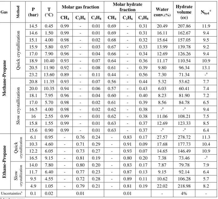
Table 6. The results of quick and slow crystallization processes for all the mixtures
Gas M et h o d P (bar) T (°C)
Molar gas fraction Molar hydrate
fraction Water conv.(%) Hydrate volume (cc) Nhyd c CH4 C2H6 C3H8 CH4 C2H6 C3H8 M et ha ne -P ro pa ne Qu ick cr y stallizatio n 14.5 0.45 0.99 - 0.01 0.69 - 0.31 20.49 207.86 11.9 14.6 1.50 0.99 - 0.01 0.69 - 0.31 16.11 162.67 9.4 15.1 4.00 0.98 - 0.02 0.68 - 0.32 15.64 157.05 9.5 15.9 5.80 0.97 - 0.03 0.67 - 0.33 13.99 139.78 9.2 17.0 7.90 0.96 - 0.04 0.66 - 0.34 12.69 126.26 9.4 18.9 10.40 0.93 - 0.07 0.64 - 0.36 11.17 110.54 10.9 20.5 11.90 0.92 - 0.08 0.61 - 0.39 9.80 96.34 13.1 23.2 13.60 0.89 - 0.11 0.44 - 0.56 7.30 71.34 -a Slo w cr y stallizatio n 20.8 11.35 0.93 - 0.07 0.56 - 0.44 5.32 53.62 7.7 20.0 10.35 0.94 - 0.06 0.57 - 0.43 6.03 60.41 7.4 18.1 7.95 0.96 - 0.04 0.60 - 0.40 8.23 81.90 7.2 17.0 5.70 0.98 - 0.02 0.61 - 0.39 8.56 84.78 6.5 16.5 4.00 0.98 - 0.02 0.62 - 0.38 -a -a 9.4 16 2.55 0.99 - 0.01 0.62 - 0.38 11.06 108.21 7.5 15.8 1.55 0.99 - 0.01 0.63 - 0.37 12.69 123.33 8.5 15.6 0.90 0.99 - 0.01 0.63 - 0.37 -a -a 6.4 E tha ne -P ro pa ne Qu ick cr y st al li za ti o n 6.1 0.95 - 0.76 0.24 - 0.83 0.17 27.57 278.72 11.3 10.3 4.60 - 0.71 0.29 - 0.91 0.09 17.68 177.73 10.4 12.2 6.05 - 0.73 0.27 - 0.93 0.07 14.65 146.49 10.9 16.5 9.15 - 0.81 0.19 - 0.80 0.20 7.38 73.46 -a Slo w cr y st al li za ti o n 14.0 7.80 - 0.80 0.20 - 0.83 0.17 7.87 79.78 7.9 11.7 6.40 - 0.77 0.23 - 0.87 0.13 9.15 92.14 6.4 9.5 4.55 - 0.72 0.28 - 0.89 0.11 10.62 106.28 5.7 4.9 1.05 - 0.79 0.21 - 0.81 0.19 22.02 218.98 8.2 Uncertaintiesb 0.1 0.02 0.01 0.01 - 4% - a Analyses error b
The calculation of uncertainties can be found in our previous work (Le Quang, 2016)
c Hydration number
Pressure-temperature diagram of two different methods for methane-propane and ethane-propane mixtures is presented in Figure 5. Ordinarily, for these two mixtures, the final pressure for both crystallization rates should be identical but significantly, they are slightly different. This clarifies
that kinetics have a substantial impact on the final equilibrium. Although for methane-propane mixture, at a given temperature the equilibrium pressure at slow crystallization process is higher than quick crystallization process (For example at 7.9°C and 10.3°C), the inverse was observed for ethane-propane mixture (For example at 4.6°C).
Table 7. A summary of influence of the rate of crystallization
C2H6-C3H8 Method P (bar) T (°C) xC2H6 in hydrate Hydration number Water Conversion Slow 4.9 1.05 0.81 8.2 22.02% Quick 6.1 0.95 0.83 11.3 27.57% CH4-C3H8 Method P (bar) T (°C) xCH4 in hydrate Hydration number Water Conversion Slow 15.8 1.55 0.63 8.5 12.69% Quick 14.6 1.50 0.69 9.4 16.11%
Figure 5. Pressure-temperature diagram of two different methods for methane/propane and ethane/propane mixtures
In order to optimize the Kihara parameters for a guest molecule, it is necessary to choose a set of liquid-hydrate equilibrium data. To avoid the impact of kinetic and non-equilibrium conditions, it is suggested to use equilibrium data for pure gas hydrates. Moreover the set of data must be consistent. This set of Kihara parameters must provide the equilibrium pressure which satisfies equation 8. When the deviation is a function of Kihara parameters, the minimum of deviation selects the best set of Kihara parameters. This is not the case for pure propane; the minimum of deviation function cannot be found. Hence, the equilibrium data from a mixture containing propane furnishes a satisfactory solution. However, the Kihara parameters for other components must be known. The other difficulty is that the experimental data for the mixed gas hydrates must be at thermodynamic equilibrium. It means that for the mixed gas hydrates data, the impact of kinetic effects must be minimized as much as possible. Therefore, the equilibrium results from slow crystallization seem to be an important key in retrieving the Kihara parameters for propane. About 61 experimental points from literature as well as our results of slow crystallization were used to optimize Kihara parameters of propane (Deaton and Frost, 1946; Robinson and Metha, 1971; Adisasmito and Sloan, 1992; Tohidi et al., 1993; Nixdorf and Oellrich, 1997; Yasuda and Ohmura, 2008).
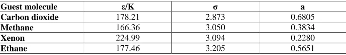
Figure 6 presents the optimization of 𝜀/𝐾, 𝜎 values and their corresponding average deviations for three different mixtures including propane as well as pure propane’s experimental data. As it is clear in the figure, for pure propane a global minimum of average deviation cannot be found to generate the best set of Kihara parameters. Ergo, we used our experimental results from slow crystallization of methane-propane mixed hydrates as well as experimental results for xenon-propane and carbon dioxide-xenon-propane from literature (Adisasmito and Sloan, 1992; Tohidi et al., 1993). It should be noted that, these experimental results from literature were carefully selected based on the fact that the Kihara parameters for methane, xenon and carbon dioxide had been obtained by our team and they are given in Table 8 (Herri et al., 2011; Herri and Chassefière, 2012).
Table 8. ε/K and σ for the guest molecules from our previous work (Herri et al., 2011; Herri and Chassefière, 2012), a from literature (Barrer and Edge, 1967; Sloan, 1998)
Guest molecule ε/K σ a
Carbon dioxide 178.21 2.873 0.6805
Methane 166.36 3.050 0.3834
Xenon 224.99 3.094 0.2280
Ethane 177.46 3.205 0.5651
As illustrated in figure 6, the Kihara parameters curves for methane-propane (slow crystallization), carbon dioxide-propane and xenon-propane meet each other at a point specified on the curve. This point provides the best set of Kihara parameters for propane in the mixtures. ε/K and σ for propane based on this point is 195.0 and 3.34, respectively.
Figure 6. 𝜺/𝑲 versus 𝝈 for pure propane and three different mixtures including propane corresponding to average deviation by implementing experimental data from this paper and literature (Deaton and Frost, 1946; Nixdorf and
Oellrich, 1997; Yasuda and Ohmura, 2008)
4.3. Test of Thermodynamic model 4.3.1. Equilibrium pressure
Different Kihara parameters for propane can be found in the literature due to the usage of the various experimental data and also thermodynamic properties. They are listed in Table 9.
Table 9. Different sets of Kihara parameters for propane
Reference ε/K σ a
(Sloan, 1998) 203.31 3.3093 0.6502
(Ng and Robinson, 1977) 213.58 3.2296 0.6700
(Barkan and Sheinin, 1993) 194.55 3.3144 0.8340
(Moradi and Khosravani, 2013) 493.70 4.5190 0.6502
The accuracy of these sets of propane’s Kihara parameters for predicting the hydrate equilibrium pressure has been calculated and compared to several experimental data of mixed gas hydrates from the literature. The results are presented in Table 10.
Table 10. The comparison between the different sets of propane Kihara parameters for predicting hydrate equilibrium pressure Str uct ure Numb er o f equil ibrium po ints
Kihara parameters (The values were presented in Table 9) Ng a nd Ro bin so n B a rka n a nd Sh eini n Slo a n M o ra di a nd K ho sra v a ni T hi s wo rk
Mixtures Experimental data resources Average Deviation (%)
CH4-C3H8
(McLeod and Campbell, 1961) II 17 38.7 51.0 37.4I 85.0 26.6I
(Deaton and Frost, 1946) II 24 20.5 30.2 20.4 306.0 18.0
(Nixdorf and Oellrich, 1997) II 7 27.4 42.0 26.8 103.9 14.5
(Verma et al., 1975) II 12 33.9 8.8 34.7 386.0I 24.4I
Our results (Quick crys.) II 8 14.8 29.8 14.1 177.0 3.2
(Song and Kobayashi, 1982) II 11 13.7 28.9 13.0 397.0 9.7
C2H6-C3H8
(Mooijer – van den Heuvel, 2004) I 11 67.8II 67.8 65.7 67.8II 15.8
(Jager, 2001) I 7 71.8II 71.8II 66.2 71.9 11.0
(Nixdorf and Oellrich, 1997) I 6 73.8 7.5 42.0 8.0 17.5
Our results (Quick crys.) I 4 82.6 18.2 55.7 19.0 24.0
Our results (Slow crys.) I 4 79.8 26.8 49.7 27.6 16 .0
CO2-C3H8 (Robinson and Metha, 1971) II 37 34.0 52.5 33.6 216.0 14.6I
CH4-C2H6
-C3H8
(Nixdorf and Oellrich, 1997) II 7 13.0 29.0 12.6 69.2I 4.5
(Dharmawardhana et al., 1980) I 11 50.9II 7.0 44.2 7.0 24.5
(Yasuda and Ohmura, 2008) II 20 16.2 29.4 7.9I 65.6 12.5
(Le Quang et al., 2015) I 8 15.5 22.0 10.8 13.5II 16.8
CO2-CH4
-C3H8
(Bishnoi and Dholabhai, 1999) II 4 29.7 42.5 23.2I 75.0 20.1
Average deviation (%) 198 30.6 32.2 26.9 142.1 14.5
A wide range of experimental equilibrium data from literature and our experiments (198 equilibrium points) have been used to investigate the accuracy of the thermodynamic model based on our new set of Kihara parameters and also Kihara parameters from the other researchers. As demonstrated in the table, the average deviation of our thermodynamic model based on the new Kihara parameters is 14.5% and it is considerably lower than the other better known sets (26.9% for Sloan, 30.6% for Ng and Robinson, 32.2% for Barkan and Sheinin and 142.1% for Moradi and Khosravani). The other advantage of our new thermodynamic model is uniformity in other words: for all the mixtures, the average deviation is relatively quite small, whilst the average deviation of the other models varies significantly, according to the components
of the mixtures and also literature resources. Another interesting observation in Table 10 is that for C2H6-C3H8 mixture, the result of thermodynamic model for slow crystallization rate is better
than quick crystallization rate (16% compare to 24%). This clarifies that the crystallization of mixed gas hydrate at slow crystallization rate can occur at thermodynamic equilibrium. As mentioned, at quick crystallization, the kinetics consideration may affect the results.
4.3.2. Gas composition in hydrate phase
As stated earlier, the gas composition in hydrate phase is a new challenge and it is very difficult to find pertinent data in literature. Our objectives were to investigate the hydrate temperature-pressure and gas composition dynamically in hydrate phase; not only at the final state (overall thermodynamic equilibrium), but also during the crystallization at non-equilibrium conditions (local equilibrium). Hence, the thermodynamic model based on the new Kihara parameter was used to model the evolution of hydrate composition from the initial state to final state (Methane-propane and ethane-(Methane-propane mixtures at two different crystallization rates). The results are presented in Table 11. It should be highlighted that the results of slow crystallization process for methane-propane mixture were not presented in this table, as its results had been already used for the thermodynamic model.
Table 11. Gas composition in hydrate phase, experimental and predicted results
Mixture Method P (bar) T (°C) S tru ctu re Experimental Hydrate compositions Predicted hydrate compositions CH4 C2H6 C3H8 CH4 C2H6 C3H8 M et ha ne -P ro pa ne Qu ick cr y stallizatio n 14.5 0.45 II 0.69 - 0.31 0.65 - 0.35 14.6 1.5 II 0.69 - 0.31 0.64 - 0.36 15.1 4 II 0.69 - 0.31 0.64 - 0.36 15.9 5.8 II 0.68 - 0.32 0.63 - 0.37 17 7.9 II 0.66 - 0.34 0.63 - 0.37 18.9 10.4 II 0.64 - 0.36 0.62 - 0.38 20.5 11.9 II 0.61 - 0.39 0.62 - 0.38 23.2 13.6 II 0.44 - 0.56 0.62 - 0.38 Average deviation (%) 9.1 - 10.6 E tha ne -P ro pa ne Qu ick cr y stallizatio n 6.1 0.95 I - 0.83 0.17 - 0.65 0.35 10.3 4.60 I - 0.91 0.09 - 0.62 0.38 12.2 6.05 I - 0.93 0.07 - 0.65 0.35 16.5 9.15 I - 0.80 0.20 - 0.76 0.24 Average deviation (%) - 22.6 237 Slo w cr y stallizatio n 14 7.80 I - 0.83 0.17 - 0.74 0.26 11.7 6.40 I - 0.87 0.13 - 0.69 0.31 9.5 4.55 I - 0.89 0.11 - 0.63 0.37 4.9 1.05 I - 0.82 0.18 - 0.70 0.30 Average deviation (%) - 18.9 127
As Table 11 clarifies, for methane-propane mixture, the simulation results have a satisfactory accordance with experimental results during the crystallization and at final state (the average deviation for methane and propane are 9.1% and 10.6% respectively). For ethane-propane mixture, although the accuracy of prediction for the major component Ethane is 22.6% and 18.9% for quick and slow crystallization, respectively, for the case of Propane, the average deviation is huge due to low percentage of propane molecules in the cavities. If we consider the composition of major component as a reference of comparison, it is clear that the results of gas composition in hydrate phase for slow crystallization experiments are close to the thermodynamic equilibrium. This means that the hydrate crystals are more homogeneous. But at quick crystallization process where the driving force is high, kinetics effects could dominate. Indeed, gas dissolution in liquid phase depends on the driving force, mass transfer coefficients as well as the characteristics of the contact surface. Therefore, instantaneous gas concentration in the liquid phase should not be at thermodynamic equilibrium. Finally, the driving force for the crystallization does not match what we could expect from only one gas’s thermodynamic considerations. The final solid phase should be the result of all mass transfer considerations (Le Quang et al., 2015).
Moreover, it should be emphasized that it is difficult to optimize a unique set of Kihara parameters to model both pure propane hydrate and mixtures that include propane. Hence we concluded that for using van der Waals and Platteuw model based on Kihara approach, it is necessary to use different sets of Kihara parameters based on the kind of feed gas (pure propane or a mixture involving propane).
5. Conclusion and possible future work
During the last decade, our GasHyDyn team has measured equilibrium data for many gas mixtures, and this document adds new data and extends previous techniques for the mixed hydrates involving propane at equilibrium and non-equilibrium conditions. In truth, the impetus for this research was that we found no appropriate information of hydrate composition in literature for the mixtures including propane. In the experiments, two different rates of crystallization (Quick and slow crystallization) were performed in order to study the significance of kinetics. What was desired was not a snapshot but an overall time sequence of the equilibrium temperature and pressure during the crystallization at non-equilibrium conditions as well as at final state for two crystallization processes were obtained as well as the gas composition in hydrate phase, volume of hydrate and water conversion. Furthermore a thermodynamic model based on classical van der Waals and Platteeuw approach was used to investigate the effects of kinetics. New Kihara parameters of propane were obtained in this study based on our results of slow crystallization and it were benchmarked with the other values of propane Kihara parameters in literature.
The results of experiments show that the equilibrium pressure at a desired temperature for two crystallization processes is slightly different. It was also observed that the enclathration of
heavier hydrocarbon is more influential at slow crystallization process. Plus, water conversion and the volume of hydrate formed with the quick crystallization process were more prominent than with slow crystallization.
The simulation results based on the new Kihara parameters of propane confirm that it has an adequate accordance with our and known experimental data and thus is useful to predict the hydrate equilibrium pressure for a wide range of temperatures. It was also noticed that the results of thermodynamic model is closer to the results of slow crystallization process. Hence, we suggest that the hydrate crystallization of a gas mixture occurs at slow crystallization where the impact of kinetics can be neglected as much as possible. The hydrate compositions at final state and also during the crystallization were obtained in our experiments. Simulation shows that by considering the composition of major component as a reference of comparison, the results of gas composition in hydrate phase for slow crystallization experiments are close to the thermodynamic equilibrium. This signifies that at slow crystallization, hydrate crystals appear to be more homogeneous.
Finally, it looks difficult to compute good Kihara parameters to model both pure propane hydrates and some mixed hydrates involving propane (such as methane-propane). This indicates that there might not be a unique set of Kihara parameters for propane which satisfied standard approach of van der Waals and Platteeuw model with the Kihara potential. We never faced this problem in our previous work relative to CH4, C2H6, CO2 gas mixtures. For example, methane
had a unique set of Kihara parameters which could be used for mixtures involving methane as well as pure methane. But for propane, it was impossible to optimize a set of Kihara parameters which can be used to model both pure propane and also mixtures including propane. Hence we recommend that there should be two different sets of Kihara parameters for propane: one to model pure propane hydrates, and another to model mixtures involving propane.
These new investigations; the differences in hydrate volume, hydrate compositions and final pressures, could change and introduce the new fundamental questions and ideas based on the thermodynamic equilibrium of mixed gas hydrates. Our observations could also have a significant impact on design calculations in which the assumption of thermodynamic equilibrium is made in the real world. For example, over estimation of the hydrates volume in the pipe-lines, equilibrium conditions in energy storage and transportation or carbon capture and sequestration and thus increasing costs or loss of efficiency.
Acknowledgments
The authors would like to thanks the members of “GasHyDyn” team for their technical supports; Fabien Chauvy, Richard Drogo and Hubert Faure and Chris Yukna for his help in proofreading
References
Adisasmito, S., Sloan, D.E., 1992. Hydrates of Hydrocarbon Gases Containing Carbon Dioxide. J. Chem. Eng. Data 37, 343–349. https://doi.org/DOI: 10.1021/je00007a020
Ando, N., Kuwabara, Y., Mori, Y.H., 2012. Surfactant effects on hydrate formation in an unstirred gas/liquid system: An experimental study using methane and micelle-forming surfactants. Chem. Eng. Sci. 73, 79–85. https://doi.org/10.1016/j.ces.2012.01.038
Balakin, B.V., Lo, S., Kosinski, P., Hoffmann, A.C., 2016. Modelling agglomeration and deposition of gas hydrates in industrial pipelines with combined CFD-PBM technique. Chem. Eng. Sci. 153, 45–57. https://doi.org/10.1016/j.ces.2016.07.010
Barkan, E.S., Sheinin, D.A., 1993. A general technique for the calculation of formation conditions of natural gas hydrates. Fluid Phase Equilibria 86, 111–136. https://doi.org/10.1016/0378-3812(93)87171-V
Barrer, R.M., Edge, A.V.J., 1967. Gas Hydrates Containing Argon, Krypton and Xenon: Kinetics and Energetics of Formation and Equilibria. Proc. R. Soc. Math. Phys. Eng. Sci. 300, 1– 24. https://doi.org/10.1098/rspa.1967.0154
Bishnoi, P.., Dholabhai, P.D., 1999. Equilibrium conditions for hydrate formation for a ternary mixture of methane, propane and carbon dioxide, and a natural gas mixture in the presence of electrolytes and methanol. Fluid Phase Equilibria 158–160, 821–827. https://doi.org/10.1016/S0378-3812(99)00103-X
Bouillot, B., Herri, J.-M., 2017. Volume and Non-Equilibrium Crystallization of Clathrate Hydrates, in: Gas Hydrates: Fundamentals, Characterization and Modeling. Wiley, pp. 227–282.
Bouillot, B., Herri, J.-M., 2015. Framework for clathrate hydrate flash calculations and implications on the crystal structure and final equilibrium of mixed hydrates. Fluid Phase Equilibria. https://doi.org/10.1016/j.fluid.2015.10.023
Chen, J., Yan, K.-L., Chen, G.-J., Sun, C.-Y., Liu, B., Ren, N., Shen, D.-J., Niu, M., Lv, Y.-N., Li, N., Sum, A.K., 2015. Insights into the formation mechanism of hydrate plugging in pipelines. Chem. Eng. Sci. 122, 284–290. https://doi.org/10.1016/j.ces.2014.09.039 Danesh, A., 1998. PVT and Phase Behaviour Of Petroleum Reservoir Fluids, Volume 47.
Elsevier Science, Amsterdam ; New York.
Deaton, W.M., Frost, E.M., 1946. Gas hydrates and their relation to the operation of natural-gas pipe lines. Printed by the American Gas Association.
Dharmawardhana, P.B., Parrish, W.R., Sloan, E.D., 1980. Experimental Thermodynamic Parameters for the Prediction of Natural Gas Hydrate Dissociation Conditions. Ind. Eng. Chem. Fundam. 19, 410–414. https://doi.org/10.1021/i160076a015
Dholabhai, P.D., Bishnoi, P.R., 1994. Hydrate equilibrium conditions in aqueous electrolyte solutions: mixtures of methane and carbon dioxide. J. Chem. Eng. Data 39, 191–194. https://doi.org/10.1021/je00013a054
Duc, N.H., Chauvy, F., Herri, J.-M., 2007. CO2 capture by hydrate crystallization – A potential solution for gas emission of steelmaking industry. Energy Convers. Manag. 48, 1313– 1322. https://doi.org/10.1016/j.enconman.2006.09.024
Eslamimanesh, A., Babaee, S., Gharagheizi, F., Richon, D., 2013. Assessment of Clathrate Hydrate Phase Equilibrium Data for CO2 + CH4/N2 +Water System. Fluid Phase Equilibria 349, 71–82. https://doi.org/DOI: 10.1016/j.fluid.2013.03.015
Eslamimanesh, A., Mohammadi, A.H., Richon, D., Naidoo, P., Ramjugernath, D., 2012. Application of gas hydrate formation in separation processes: A review of experimental studies. J. Chem. Thermodyn. 46, 62–71. https://doi.org/10.1016/j.jct.2011.10.006
Ghavipour, M., Ghavipour, M., Chitsazan, M., Najibi, S.H., Ghidary, S.S., 2013. Experimental study of natural gas hydrates and a novel use of neural network to predict hydrate formation conditions. Chem. Eng. Res. Des. 91, 264–273. https://doi.org/10.1016/j.cherd.2012.08.010
Handa, Y.P., Tse, J.S., 1986. Thermodynamic properties of empty lattices of structure I and structure II clathrate hydrates. J. Phys. Chem. 90, 5917–5921. https://doi.org/10.1021/j100280a092
Herri, J.-M., Bouchemoua, A., Kwaterski, M., Brântuas, P., Galfré, A., Bouillot, B., Douzet, J., Ouabbas, Y., Cameirao, A., 2014. Enhanced Selectivity of the Separation of CO2 from N2 during Crystallization of Semi-Clathrates from Quaternary Ammonium Solutions. Oil Gas Sci. Technol. – Rev. D’IFP Energ. Nouv. 69, 947–968. https://doi.org/10.2516/ogst/2013201
Herri, J.-M., Bouchemoua, A., Kwaterski, M., Fezoua, A., Ouabbas, Y., Cameirao, A., 2011. Gas hydrate equilibria for CO2–N2 and CO2–CH4 gas mixtures—Experimental studies and thermodynamic modelling. Fluid Phase Equilibria 301, 171–190. https://doi.org/10.1016/j.fluid.2010.09.041
Herri, J.-M., Chassefière, E., 2012. Carbon dioxide, argon, nitrogen and methane clathrate hydrates: Thermodynamic modelling, investigation of their stability in Martian atmospheric conditions and variability of methane trapping. Planet. Space Sci. 73, 376– 386. https://doi.org/10.1016/j.pss.2012.07.028
Herri, J.-M., Kwaterski, M., 2012. Derivation of a Langmuir type of model to describe the intrinsic growth rate of gas hydrates during crystallisation from gas mixtures. Chem. Eng. Sci. 81, 28–37. https://doi.org/10.1016/j.ces.2012.06.016
Holder, G.D., Corbin, G., Papadopoulos, K.D., 1980. Thermodynamic and Molecular Properties of Gas Hydrates from Mixtures Containing Methane, Argon, and Krypton. Ind. Eng. Chem. Fundam. 19, 282–286. https://doi.org/10.1021/i160075a008
Holder, G.D., Zetts, S.P., Pradhan, N., 1988. Phase Behavior in Systems Containing Clathrate Hydrates: A Review. Rev. Chem. Eng. 5, 1–70. https://doi.org/10.1515/REVCE.1988.5.1-4.1
Jager, M.D., 2001. High Pressure Studies of Hydrate Phase Inhibition Using Raman Spectroscopy (Ph.D. Chemical Engineering Thesis). Colorado School of Mines, USA. Javanmardi, J., Moshfeghian, M., Maddox, R.N., 1998. Simple Method for Predicting
Gas-Hydrate-Forming Conditions in Aqueous Mixed-Electrolyte Solutions. Energy Fuels 12, 219–222. https://doi.org/10.1021/ef9701652
Ji, C., Ahmadi, G., Smith, D.H., 2001. Natural gas production from hydrate decomposition by depressurization. Chem. Eng. Sci. 56, 5801–5814. https://doi.org/10.1016/S0009-2509(01)00265-2
Katz, D.L., 1945. Prediction of Conditions for Hydrate Formation in Natural Gases. Trans. AIME 160, 140–149. https://doi.org/10.2118/945140-G
Le Quang, D., 2016. Investigation of non-equilibrium crystallization of mixed gas clathrates hydrates: an experimental study compared to thermodynamic modeling with and without flash calculation. Ecole des mines de Saint-Etienne.
Le Quang, D., Le Quang, D., Bouillot, B., Herri, J.-M., Glenat, P., Duchet-Suchaux, P., 2015. Experimental procedure and results to measure the composition of gas hydrate, during
crystallization and at equilibrium, from N2–CO2–CH4–C2H6–C3H8–C4H10 gas mixtures. Fluid Phase Equilibria. https://doi.org/10.1016/j.fluid.2015.10.022
Linga, P., Kumar, R., Englezos, P., 2007. Gas hydrate formation from hydrogen/carbon dioxide and nitrogen/carbon dioxide gas mixtures. Chem. Eng. Sci. 62, 4268–4276. https://doi.org/10.1016/j.ces.2007.04.033
Maghsoodloo Babakhani, S., Alamdari, A., 2015. Effect of maize starch on methane hydrate formation/dissociation rates and stability. J. Nat. Gas Sci. Eng. 26, 1–5. https://doi.org/10.1016/j.jngse.2015.05.026
Maghsoodloo Babakhani, S., Bahmani, M., Shariati, J., Badr, K., Balouchi, Y., 2015. Comparing the capability of artificial neural network (ANN) and CSMHYD program for predicting of hydrate formation pressure in binary mixtures. J. Pet. Sci. Eng. 136, 78–87. https://doi.org/10.1016/j.petrol.2015.11.002
Makogon, Y.F., 2010. Natural gas hydrates – A promising source of energy. J. Nat. Gas Sci. Eng. 2, 49–59. https://doi.org/10.1016/j.jngse.2009.12.004
McKoy, V., Sinanoğlu, O., 1963. Theory of Dissociation Pressures of Some Gas Hydrates. J. Chem. Phys. 38, 2946. https://doi.org/10.1063/1.1733625
McLeod, H.O., Campbell, J.M., 1961. Natural Gas Hydrates at Pressures to 10,000 psia. J. Pet. Technol. 13, 590–594. https://doi.org/10.2118/1566-G-PA
Mooijer – van den Heuvel, M.., 2004. Phase Behaviour and Structural Aspects of Ternary Clathrate Hydrate Systems The Role of Additives. Technische Universiteit Delft, Netherlands.
Moradi, G., Khosravani, E., 2013. Modeling of hydrate formation conditions for CH4, C2H6, C3H8, N2, CO2 and their mixtures using the PRSV2 equation of state and obtaining the Kihara potential parameters for these components. Fluid Phase Equilibria 338, 179–187. https://doi.org/10.1016/j.fluid.2012.11.010
Ng, H.-J., Robinson, D.B., 1977. The prediction of hydrate formation in condensed systems. AIChE J. 23, 477–482. https://doi.org/10.1002/aic.690230411
Nixdorf, J., Oellrich, L.R., 1997. Experimental determination of hydrate equilibrium conditions for pure gases, binary and ternary mixtures and natural gases. Fluid Phase Equilibria 139, 325–333. https://doi.org/10.1016/S0378-3812(97)00141-6
Ogata, K., Hashimoto, S., Sugahara, T., Moritoki, M., Sato, H., Ohgaki, K., 2008. Storage capacity of hydrogen in tetrahydrofuran hydrate. Chem. Eng. Sci. 63, 5714–5718. https://doi.org/10.1016/j.ces.2008.08.018
Parrish, W.R., Prausnitz, J.M., 1972. Dissociation Pressures of Gas Hydrates Formed by Gas Mixtures. Ind. Eng. Chem. Process Des. Dev. 11, 26–35. https://doi.org/10.1021/i260041a006
Robinson, D.B., Metha, B.R., 1971. Hydrates In the PropaneCarbon Dioxide- Water System. J. Can. Pet. Technol. 10. https://doi.org/10.2118/71-01-04
Sherwood, A.E., Prausnitz, J.M., 1964. Intermolecular Potential Functions and the Second and Third Virial Coefficients. J. Chem. Phys. 41, 429. https://doi.org/10.1063/1.1725884 Sloan, E.D., Koh, J., Carolyn, 2007. Clathrate Hydrates of Natural Gases, 3rd ed. Taylor &
Francis.
Sloan, J.E.D., 1998. Clathrate Hydrates of Natural Gases, Second Edition, Revised and Expanded. CRC Press.
Song, K.Y., Kobayashi, R., 1982. Measurement and interpretation of the water content of a methane-propane mixture in the gaseous state in equilibrium with hydrate. Ind. Eng. Chem. Fundam. 21, 391–395. https://doi.org/10.1021/i100008a013
Stackelberg, M. v., Müller, H.R., 1951. On the Structure of Gas Hydrates. J. Chem. Phys. 19, 1319. https://doi.org/10.1063/1.1748038
Tee, L.S., Gotoh, S., Stewart, W.E., 1966b. Molecular Parameters for Normal Fluids. Kihara Potential with Spherical Core. Ind. Eng. Chem. Fundam. 5, 363–367. https://doi.org/10.1021/i160019a012
Thakore, J.L., Holder, G.D., 1987. Solid vapor azeotropes in hydrate-forming systems. Ind. Eng. Chem. Res. 26, 462–469. https://doi.org/10.1021/ie00063a011
Tohidi, B., Burgass, R.W., Danesh, A., Todd, A.C., 1993. Measurement and Prediction of Amount and Composition of Equilibrium Phases in Heterogeneous Systems Containing Gas Hydrates. Presented at the SPE Student Paper Contest, Aberdeen, UK.
van der Waals, J.H., Platteeuw, J.C., 1959. Clathrate Solutions, in: Prigogine, I. (Ed.), Advances in Chemical Physics. John Wiley & Sons, Inc., Hoboken, NJ, USA, pp. 1–57.
Verma, Y.K., Hand, J.H., Katz, D.L., 1975. Gas hydrates from liquid hydrocarbons methane-propane-water system, in: GVC/AIChE Joint Meeting. Munich, Germany, p. 10.
Wang, X.-H., Sun, C.-Y., Chen, G.-J., He, Y.-N., Sun, Y.-F., Wang, Y.-F., Li, N., Zhang, X.-X., Liu, B., Yang, L.-Y., 2015. Influence of gas sweep on methane recovery from hydrate-bearing sediments. Chem. Eng. Sci. 134, 727–736. https://doi.org/10.1016/j.ces.2015.05.043
Wilcox, W.I., Carson, D.B., Katz, D.L., 1941. Natural Gas Hydrates. Ind. Eng. Chem. 33, 662– 665. https://doi.org/10.1021/ie50377a027
Yasuda, K., Ohmura, R., 2008. Phase Equilibrium for Clathrate Hydrates Formed with Methane, Ethane, Propane, or Carbon Dioxide at Temperatures below the Freezing Point of Water. J. Chem. Eng. Data 53, 2182–2188. https://doi.org/10.1021/je800396v
Zhou, H., Infante Ferreira, C., 2017. Effect of type-III Anti-Freeze Proteins (AFPs) on CO2 hydrate formation rate. Chem. Eng. Sci. 167, 42–53. https://doi.org/10.1016/j.ces.2017.03.060