HAL Id: hal-02405635
https://hal.archives-ouvertes.fr/hal-02405635
Submitted on 11 Dec 2019
HAL is a multi-disciplinary open access
archive for the deposit and dissemination of
sci-entific research documents, whether they are
pub-lished or not. The documents may come from
teaching and research institutions in France or
abroad, or from public or private research centers.
L’archive ouverte pluridisciplinaire HAL, est
destinée au dépôt et à la diffusion de documents
scientifiques de niveau recherche, publiés ou non,
émanant des établissements d’enseignement et de
recherche français ou étrangers, des laboratoires
publics ou privés.
Design of a Cable-Driven Parallel Robot with Grasping
Device
Antoine Martin, Stéphane Caro, Philippe Cardou
To cite this version:
Antoine Martin, Stéphane Caro, Philippe Cardou. Design of a Cable-Driven Parallel Robot with
Grasping Device. Procedia CIRP, ELSEVIER, 2018, 70, pp.290-295. �10.1016/j.procir.2018.03.105�.
�hal-02405635�
ScienceDirect
ScienceDirect
Procedia CIRP 00 (2017) 000–000
www.elsevier.com/locate/procedia
2212-8271 © 2017 The Authors. Published by Elsevier B.V.
Peer-review under responsibility of the scientific committee of the 28th CIRP Design Conference 2018.
28th CIRP Design Conference, May 2018, Nantes, France
A new methodology to analyze the functional and physical architecture of
existing products for an assembly oriented product family identification
Paul Stief *, Jean-Yves Dantan, Alain Etienne, Ali Siadat
École Nationale Supérieure d’Arts et Métiers, Arts et Métiers ParisTech, LCFC EA 4495, 4 Rue Augustin Fresnel, Metz 57078, France
* Corresponding author. Tel.: +33 3 87 37 54 30; E-mail address: [email protected]
Abstract
In today’s business environment, the trend towards more product variety and customization is unbroken. Due to this development, the need of agile and reconfigurable production systems emerged to cope with various products and product families. To design and optimize production systems as well as to choose the optimal product matches, product analysis methods are needed. Indeed, most of the known methods aim to analyze a product or one product family on the physical level. Different product families, however, may differ largely in terms of the number and nature of components. This fact impedes an efficient comparison and choice of appropriate product family combinations for the production system. A new methodology is proposed to analyze existing products in view of their functional and physical architecture. The aim is to cluster these products in new assembly oriented product families for the optimization of existing assembly lines and the creation of future reconfigurable assembly systems. Based on Datum Flow Chain, the physical structure of the products is analyzed. Functional subassemblies are identified, and a functional analysis is performed. Moreover, a hybrid functional and physical architecture graph (HyFPAG) is the output which depicts the similarity between product families by providing design support to both, production system planners and product designers. An illustrative example of a nail-clipper is used to explain the proposed methodology. An industrial case study on two product families of steering columns of thyssenkrupp Presta France is then carried out to give a first industrial evaluation of the proposed approach.
© 2017 The Authors. Published by Elsevier B.V.
Peer-review under responsibility of the scientific committee of the 28th CIRP Design Conference 2018. Keywords: Assembly; Design method; Family identification
1. Introduction
Due to the fast development in the domain of communication and an ongoing trend of digitization and digitalization, manufacturing enterprises are facing important challenges in today’s market environments: a continuing tendency towards reduction of product development times and shortened product lifecycles. In addition, there is an increasing demand of customization, being at the same time in a global competition with competitors all over the world. This trend, which is inducing the development from macro to micro markets, results in diminished lot sizes due to augmenting product varieties (high-volume to low-volume production) [1]. To cope with this augmenting variety as well as to be able to identify possible optimization potentials in the existing production system, it is important to have a precise knowledge
of the product range and characteristics manufactured and/or assembled in this system. In this context, the main challenge in modelling and analysis is now not only to cope with single products, a limited product range or existing product families, but also to be able to analyze and to compare products to define new product families. It can be observed that classical existing product families are regrouped in function of clients or features. However, assembly oriented product families are hardly to find.
On the product family level, products differ mainly in two main characteristics: (i) the number of components and (ii) the type of components (e.g. mechanical, electrical, electronical).
Classical methodologies considering mainly single products or solitary, already existing product families analyze the product structure on a physical level (components level) which causes difficulties regarding an efficient definition and comparison of different product families. Addressing this
Procedia CIRP 70 (2018) 290–295
2212-8271 © 2018 The Authors. Published by Elsevier B.V.
Peer-review under responsibility of the scientific committee of the 28th CIRP Design Conference 2018. 10.1016/j.procir.2018.03.105
© 2018 The Authors. Published by Elsevier B.V.
Peer-review under responsibility of the scientific committee of the 28th CIRP Design Conference 2018.
Procedia CIRP 00 (2018) 000–000 www.elsevier.com/locate/procedia
28th CIRP Design Conference, May 2018, Nantes, France
Design of a Cable-Driven Parallel Robot with Grasping Device
Antoine Martin
a,*, St´
ephane Caro
b, Philippe Cardou
ca
Centrale Nantes, LS2N, UMR CNRS 6004, 1 rue de la No¨e, 44321 Nantes, France
b
CNRS, LS2N, UMR CNRS 6004, 1 rue de la No¨e, 44321 Nantes, France
c
Universit´e Laval, 1065 Avenue de la m´edecine, Qu´ebec G1V 0A6, Canada ∗Corresponding author. Tel.: +33-0671996080. E-mail address: [email protected]
Abstract
Cable-Driven Parallel Robots (CDPRs) are composed of a base frame and a moving-platform. A set of cables actuated by winches and guided by pulleys on the base frame are attached to the moving-platform. Those cables are used to generate motions or to apply forces to the moving-platform throughout its workspace. CDPRs are being increasingly used in industry due to several advantages provided by the cables such as a large translational workspace, a high payload-to-weight ratio and high velocities and accelerations. However since the cables can only pull the moving-platform, the latter cannot go out of the robot base frame bounded by the pulleys. An example is the treatment of large structures by using a CDPR. The structure itself can be used to hold the pulleys of the CDPR and the moving-platform would therefore need to go out of the robot volume to reach it. To overcome this issue a grasping device is mounted onto the moving-platform to grab the structure. It should be noted that when the structure is grabbed, the model of the overall system changes as the motions of the moving-platform is not only controlled by cables anymore, but the contact between the grasping device and the structure should be considered. This paper deals with the conceptual design of a grasping device for CDPRs and the definition of two workspaces. The first workspace characterize the area covered by the moving-platform when the latter is free of contact with the environment. The second workspace is the region that the gripper can follow dur-ing grippdur-ing phase. It turns out that the robot workspace increases while considerdur-ing the structure graspdur-ing into the system modeldur-ing.
c
2018 The Authors. Published by Elsevier B.V.
Peer-review under responsibility of the scientific committee of the 28th CIRP Design Conference 2018.
Keywords: Cable-Driven Parallel Robots, Grasping, Design, Modeling, Workspace
1. Introduction
Because of their large workspace, Cable-Driven Paral-lel Robots (CDPRs) seem well suited for the maintenance of large structures such as bridges or buildings. Several workspaces have been studied in the literature, such as the Wrench Closure Workspace [1,2] or Wrench Feasible
Workspace[3] for the static equilibrium of CDPR. In most cases, those workspaces are included inside the volume en-closed by the pulleys guiding the cables. Indeed the cables can only pull and not push the moving-platform, there-fore limiting the pose it can reach outside of the volume of the pulleys. One technique for the moving-platform to go out from the area delimited by the pulleys is to take advantage of the dynamic behavior of the CDPR [4]. Ac-cordingly, Barrette et al. defined the Dynamic Workspace [5] of CDPRs. However, it is not realistic from an indus-trial viewpoint to use this approach to make the moving-platform move along tubes outside the CDPR wrench-closure workspace.
To the best of the author’s knowledge, two solutions exist to operate along large structures. The first one consists on the discrete reconfiguration of CDPRs [6,7] to cover the entire structure to treat. Gagliardini et al. defined a reconfiguration strategy to find a way to cover the entire structure with the smallest number of reconfigurations in [8]. However, some manual operations are still required to change the robot from one configuration to another. The second approach aims at embedded a serial manipulator onto the moving-platform to extend the workspace locally [9,10].
To avoid those drawbacks, a multi-link CDPR, namely, a CDPR with poly-articulated moving-platform, can be used. This concept was studied through the analysis of the Force-Closure Workspace in [11] or the Tensionable
Workspacein [12], but there are still few applications [13]. The main one is the modeling of the human neck by Lau et al. who developed a generalized model of multi-link CDPR in [14,15].
This paper introduces a planar CDPR with a two-link
2212-8271 c 2018 The Authors. Published by Elsevier B.V.
Peer-review under responsibility of the scientific committee of the 28th CIRP Design Conference 2018.
Procedia CIRP 00 (2018) 000–000 www.elsevier.com/locate/procedia
28th CIRP Design Conference, May 2018, Nantes, France
Design of a Cable-Driven Parallel Robot with Grasping Device
Antoine Martin
a,*, St´
ephane Caro
b, Philippe Cardou
ca
Centrale Nantes, LS2N, UMR CNRS 6004, 1 rue de la No¨e, 44321 Nantes, France
b
CNRS, LS2N, UMR CNRS 6004, 1 rue de la No¨e, 44321 Nantes, France
c
Universit´e Laval, 1065 Avenue de la m´edecine, Qu´ebec G1V 0A6, Canada ∗Corresponding author. Tel.: +33-0671996080. E-mail address: [email protected]
Abstract
Cable-Driven Parallel Robots (CDPRs) are composed of a base frame and a moving-platform. A set of cables actuated by winches and guided by pulleys on the base frame are attached to the moving-platform. Those cables are used to generate motions or to apply forces to the moving-platform throughout its workspace. CDPRs are being increasingly used in industry due to several advantages provided by the cables such as a large translational workspace, a high payload-to-weight ratio and high velocities and accelerations. However since the cables can only pull the moving-platform, the latter cannot go out of the robot base frame bounded by the pulleys. An example is the treatment of large structures by using a CDPR. The structure itself can be used to hold the pulleys of the CDPR and the moving-platform would therefore need to go out of the robot volume to reach it. To overcome this issue a grasping device is mounted onto the moving-platform to grab the structure. It should be noted that when the structure is grabbed, the model of the overall system changes as the motions of the moving-platform is not only controlled by cables anymore, but the contact between the grasping device and the structure should be considered. This paper deals with the conceptual design of a grasping device for CDPRs and the definition of two workspaces. The first workspace characterize the area covered by the moving-platform when the latter is free of contact with the environment. The second workspace is the region that the gripper can follow dur-ing grippdur-ing phase. It turns out that the robot workspace increases while considerdur-ing the structure graspdur-ing into the system modeldur-ing.
c
2018 The Authors. Published by Elsevier B.V.
Peer-review under responsibility of the scientific committee of the 28th CIRP Design Conference 2018.
Keywords: Cable-Driven Parallel Robots, Grasping, Design, Modeling, Workspace
1. Introduction
Because of their large workspace, Cable-Driven Paral-lel Robots (CDPRs) seem well suited for the maintenance of large structures such as bridges or buildings. Several workspaces have been studied in the literature, such as the Wrench Closure Workspace [1,2] or Wrench Feasible
Workspace[3] for the static equilibrium of CDPR. In most cases, those workspaces are included inside the volume en-closed by the pulleys guiding the cables. Indeed the cables can only pull and not push the moving-platform, there-fore limiting the pose it can reach outside of the volume of the pulleys. One technique for the moving-platform to go out from the area delimited by the pulleys is to take advantage of the dynamic behavior of the CDPR [4]. Ac-cordingly, Barrette et al. defined the Dynamic Workspace [5] of CDPRs. However, it is not realistic from an indus-trial viewpoint to use this approach to make the moving-platform move along tubes outside the CDPR wrench-closure workspace.
To the best of the author’s knowledge, two solutions exist to operate along large structures. The first one consists on the discrete reconfiguration of CDPRs [6,7] to cover the entire structure to treat. Gagliardini et al. defined a reconfiguration strategy to find a way to cover the entire structure with the smallest number of reconfigurations in [8]. However, some manual operations are still required to change the robot from one configuration to another. The second approach aims at embedded a serial manipulator onto the moving-platform to extend the workspace locally [9,10].
To avoid those drawbacks, a multi-link CDPR, namely, a CDPR with poly-articulated moving-platform, can be used. This concept was studied through the analysis of the Force-Closure Workspace in [11] or the Tensionable
Workspacein [12], but there are still few applications [13]. The main one is the modeling of the human neck by Lau et al. who developed a generalized model of multi-link CDPR in [14,15].
This paper introduces a planar CDPR with a two-link
2212-8271 c 2018 The Authors. Published by Elsevier B.V.
Antoine Martin et al. / Procedia CIRP 70 (2018) 290–295 291
2 A. Martin et al. / Procedia CIRP 00 (2018) 000–000
moving-platform, which is used as a gripper. The con-tact between the grasping device and the structure mod-ifies the model of the robot, which increases the part of the structure covered by the robot. The mechanism under study and its targeted applications are described in Sec. 2. Section 3 deals with the geometrico-static modeling of the mechanism at hand in both free phase, i.e, non grasping phase, and grasping phase. The manipulator workspace is analyzed in Sec. 4. Finally, some conclusions are drawn in Sec. 5.
2. Mechanism under study
Fig. 1. represents a planar CDPR with six cables, which come out of winches placed on the corner of a rect-angle represented in blue. Those cables are attached to a four degree-of-freedom moving-platform. The latter is a grasping device composed of two jaws, the upper one in red and the lower one in blue. Those jaws are linked together by a revolute joint. This revolute joint gives a fourth degree-of-freedom to the gripper, in addition to the two usual translation and the rotation of the planar moving-platform. The grasping device should grab the guide and translate it along the rib.
The static workspace of CDPR is usually contained in the volume defined as the convex hull of the pulleys. In the case where those pulleys are fixed to the external structure to be treated, one need to ensure that the moving-platform can reach it even if it is located outside of this volume. To do so, the solution studied here consists of grasping the structure. It should be noted that the geometrico-static model of the robot differs from the free phase to the grasp-ing phase.
A guide is placed inside this rib and is connected to it with a prismatic joint along the direction of the rib. The goal is to manage to move the guide along the entire rib by using the CDPR. To do so, two phases are considered. The first one, called free phase, corresponds to the motion of the moving-platform when it is only actuated by the cables. In this phase, the moving-platform is moved in the workspace of the CDPR to reach the guide and grasp it. The model of the robot changes since not only the ca-bles generate forces on the moving-platform, but also the reaction forces between the guide and the jaws of the grip-per. In the second phase, named grasping phase, the robot should be able to grab and move the guide all along the rib.
3. Geometrico-static modeling of a planar CDPR with an articulated moving-platform
3.1. Free phase
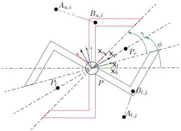
The moving-platform consists of a grasping device pre-sented in Fig.2. It is composed of two jaws, the upper one is red and the lower one is blue, linked together in a point
P by a revolute joint. The cables are attached to each jaw. The exit point (anchor point, resp.) of the ith ca-ble connected to the upper jaw is named Aui, (Bui, resp.) i= 1, . . . , 3. The exit point (anchor point, resp.) of the
Aui Bui Cui Alj Blj Clj O x b yb Fb cable rig guide moving-platform
Fig. 1. Planar CDPR with an articulated gripper
P Pr Pl xl xp xu xb φ γ Au,i Bu,i Al,j Bl,j
Fig. 2. A one degree-of-freedom gripper
jth cable connected to the lower jaw is named Alj, (Blj,
resp.) j = 1, . . . , 3.
Therefore the moving-platform has four degrees of free-dom in this planar case, the two usual translations and one rotation along with the opening/closing of the jaws. The frame attached to the moving-platform is denoted Fp = (P, xp,yp) and φ is the rotation angle between axis xb and axis xp. Fu = (P, xu,yu) is the frame attached
to the upper jaw and Fl= (P, xl,yl) the one attached to
the lower jaw. The angle between axis xl and axis xu is
denoted γ and the frame Fp is chosen so that each jaw
is placed symmetrically around it. Therefore the angle between Fp and Fuor between Fpand Flis γ2. The loop-closure equations associated to the cables attached to the upper and lower jaws are the following:
bc
ui=baui−bp − Rpbui (1a) bc
lj=balj−bp − Rpblj (1b)
uui and ulj are the unit vectors of cables Cui and Clj,
respectively: uui= cui ||cui||2 (2a) ulj= clj ||clj||2 (2b)
P Bui τui weu flu P Blj τlj wel ful (a) (b)
Fig. 3. Free body diagram of the upper jaw (a) and the lower jaw (b)
Wu (Wl, resp.) denotes the wrench matrix associated
to the upper jaw and maps the tensions exerted in cables Cui, i = 1, . . . , 3, (Clj, j = 1, . . . , 3 resp.) into the three
dimensional wrench space. Wu and Wltake the following
form: Wu= bu u1 buu2 buu3 buT u1E T Rpb u1 buTu2E T Rpb u2 buTu3E T Rpb u3 Wl= bu l1 bul2 bul3 buT l1E T Rpb l1 bu T l2E T Rpb l2 bu T l3E T Rpb l3 (3) where E = 0 −1 1 0 (4)
and R is the rotation matrix from Fb to Fp, namely:
R = cos(φ) −sin(φ)sin(φ) cos(φ)
(5)
The free body diagram of the upper jaw and of the lower jaw are represented in Fig.3(a) and Fig.3(b), respectively. To keep the moving-platform in static equilibrium, the vec-tor of the tension in the cables τuand τlneed to balance
the external wrenches weu and wel applied to the upper
and lower jaw, respectively. The center of mass of both jaws is supposed to be located in point P . fuldenotes the
wrenches applied by the lower jaw onto the upper one, and fluthe opposite. Therefore the relation Eq.(6) stands.
ful= −flu (6)
The equation for the static equilibrium of both jaws ex-pressed in point P are:
Wuτu+ ful+ weu= 03 (7a) Wlτl+ flu+ wel = 03 (7b)
To control the opening and closing of the grasping device, the relative angle between both jaws needs to be
consid-ered. With this structure, only the cables control the open-ing/closing of the grasping device if the pivot is considered without friction. A positive resulting moment generated by the cables on the upper jaw leads to an opening of the pliers, and one on the lower jaw leads to its closing. Therefore Eq.(8) needs to be verified to keep constant the relative angle between both jaws.
zT
b(Wuτu− Wlτl) = 0 (8)
The static equilibrium of the grasping device is obtained by adding Eq.(7a) to Eq.(7b) with respect to Eq.(6), and taking into account Eq.(8):
Wτ + we= 04 (9) where τ = [τu; τl], we= [weu+ wel; 0] and: W = Wu Wl zT bWu −zTbWl (10) 3.2. Grasping phase
When the moving-platform grasps the guide, the model of the robot changes due to the contact between both jaws and the guide. The free body diagram of the grasping device is shown in Fig.4. In addition to the six cables at-tached to the moving-platform, the contact between the guide and the jaws are considered in four contact points. The modeling methodology is similar to the one shown previously. Wcu and Wcl are the wrench matrices
associ-ated to the contact points between the guide and the upper jaw and the lower jaw, respectively. Those matrices are de-fined as in Eq.(3a) and Eq.(3b), but for the contact points
Cu1 and Cu2 or Cl1 and Cl2 respectively. By taking into
account the effect of the contact to the opening/closing of the jaws, we obtain the global wrench matrix for the contact points Wc: Wc= Wcu Wcl zT bWcu −zTbWcl (11)
and the static equilibrium of the moving-platform be-comes:
Wτ + Wcτc+ we= 04 (12)
where τc = [fu1; fu2; fl1; fl2] is the vector containing the
contact forces. The contact is maintained as long as τc≥
04. In addition, the static equilibrium of the guide needs to be considered. The guide in the rib is represented in Fig.5. The prismatic joint between the guide and the rib balances the forces applied to the guide in the direction normal to
Antoine Martin et al. / Procedia CIRP 70 (2018) 290–295 293
4 A. Martin et al. / Procedia CIRP 00 (2018) 000–000
r
P
Cu2 Cu1 Cl2 Cl1φ
f
u2f
u1f
l2f
l1Fig. 4. Free body diagram of the moving-platform grasping the guide
u
sx
bα
−f
u2−f
u1−f
l2−f
l1w
sFig. 5. Free body diagram of the stud inside the rib
the sliding direction us. However if the joint is considered
ideal, the only forces applied along direction us are the
contact forces between the guide and the moving-platform and the effect of gravity on the guide. Therefore to remain in static equilibrium the following equation needs to be verified:
−uT
sWcτc+ uTsws= 0. (13)
4. Workspace analysis
4.1. Free phase
This section deals with the workspace analysis of this CDPR. More precisely, we wish to evaluate the impact of the grasp on the workspace size. The workspace studied is the Weight Feasible Workspace which contains every pose of the moving platform for which the tension available in the cables can balance the effect of gravity on the moving-platform.
τ= [τ1, ..., τ6]Tdenotes the vector of the tensions applied to the six cables. The tension τi in each cable i can vary
between τ = 5N and τ = 50N , 5N being the minimal value required to keep the cable in tension and 50N being the maximal tension the actuating system can provide. Therefore, the six-dimensional box of feasible tensions is
defined as:
T = {τ ∈ R6
: τ ≺ τ ≺ τ } (14)
The side of the grasping device which is taken into account is chosen in the set of configurations S defined by:
S = {r; l} (15)
where r denotes the right side of the grasping device and
l the left side. The external forces applied on the moving-platform are generated by its weight only. A mass of
mp= 1kg is considered for this study, therefore the vector of external forces is we= [0; −mpg; 0]T applied in point P .
The workspace considered when the CDPR is in its free phase consists of every pose that Pror Plcan reach, and for
which the grasping device can perform an opening/closing operation in static equilibrium. The mathematical defini-tion associated is:
F1= {p ∈ R2: ∃c ∈ S, ∃φ ∈ [φ; φ], ∀γ ∈ [0; γ], ∃τ ∈ T , Wτ +we= 04}
(16)
In this case, the boundaries considered are φ = −π
2, φ =
π
2 for the orientation of the moving-platform and γ = π
8 for its opening. This value allows it to perform a grasping op-eration without colliding with the guide. The workspace obtained is shown in Fig.6. One can see that the moving-platform can reach the external structure only in its cor-ners.
Fig. 6. Weight Feasible Workspace of the CDPR in its free phase
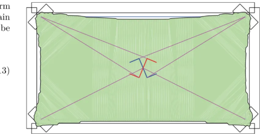
4.2. Grasping phase
When the moving-platform is grasping the guide, the model of the robot is different and therefore the definition of the previous workspace is not suited for its study. In addition to the mass of the moving-platform, the mass of the guide, arbitrarily set to ms= 1kg, is also considered.
This time, the workspace consists of every pose that Pror Pl can reach while grasping the guide, and maintain the static equilibrium of both the moving-platform and the
A. Martin et al. / Procedia CIRP 00 (2018) 000–000 5
Fig. 7. Workspace of the CDPR grasping the guide
guide. Its mathematical definition is:
F2= {p ∈ R 2 : ∃c ∈ S, ∃φ ∈ [φ; φ], ∃τ ∈ T , ∃τc ≥ 04 Wτ + Wcτc+ we= 04 uT sWcτc+ uTsws= 0 } (17)
The resulting workspace is represented in blue in Fig.7. One can see that the portion of the external structure covered by the robot is greatly increased by grasping the guide.
4.3. Analysis
On the example shown in Fig.7, the rib on the right was not covered at all in the free phase, since the cables could not pull the moving-platform further enough on the right side. Indeed, one can see that the cables coming from the right cannot generate forces in this direction since they are close to being vertical. However a large portion can be covered when the guide is grasped. This means that the contact forces between the grasping device and the guide can the balance the effect of the cables pulling it back to the center of the workspace, and that the cables can maintain the jaws closed onto the guide.
To cover the largest portion of the external structure, one need to follow the steps:
• Move the grasping device in its free phase to a grasp-ing point belonggrasp-ing to both F1 and F2 to reach the guide. Those poses correspond to the corners of the external structure in this example.
• Close the jaws to grasp the guide.
• Move along the ribs to cover the external structure in the grasping phase.
• Return to one of the grasping points. • Repeat to cover the largest portion possible.
It is to note that the workspace is different depending on which plier grasps the guide. Figure 8 represents the workspace of the robot when the right plier grasp the guide, and Fig.9 the one when the left plier grasps the guide. It is necessary to find the position where both pli-ers can grasp the guide to switch between them.
Fig. 8. Workspace of the right plier grasping the guide
Fig. 9. Workspace of the left pliers grasping the guide
5. Conclusion/Future work
This paper presents a planar CDPR with a new moving-platform with two degrees of freedom. This moving-platform consists of a grasping device that will grab a guide sliding on an external structure. The interaction with the guide can be considered as online reconfiguration since it changes the model of the robot. This reconfiguration in-creases the workspace of the CDPR, allowing it to move along a structure it could not reach from its standard con-figuration.
First, the static model of the robot equipped with the new moving-platform is developed in its free phase, and in its grasping phase. Two new workspaces are then defined to fit with the study of this concept. The first one is suited for the study of CDPR using a moving-platform with sev-eral degrees of freedom and the second for the study of CDPR interacting with an external object or structure. The analysis of those workspaces show the interest of the interaction between the moving-platform of a CDPR and its environment to improve its properties such as increase its workspace.
Those promising results are the first steps of an ongoing work in this area, that is focused on the experimental vali-dation of the results, the study of new designs of the grasp-ing device and to extend this work to spatial cases. References
[1] Marc Gouttefarde and Cl´ement M. Gosselin. On the properties and the determination of the wrench-closure workspace of planar parallel cable-driven mechanisms. In ASME 2004 International
Antoine Martin et al. / Procedia CIRP 70 (2018) 290–295 295
6 A. Martin et al. / Procedia CIRP 00 (2018) 000–000
Design Engineering Technical Conferences and Computers and Information in Engineering Conference, pages 337–346.
Ameri-can Society of Mechanical Engineers, 2004.
[2] Ethan Stump and Vijay Kumar. Workspaces of Cable-Actuated Parallel Manipulators. Journal of Mechanical Design, 128(1):159, 2006.
[3] Marc Gouttefarde, Jean-Pierre Merlet, and David Daney. Wrench-feasible workspace of parallel cable-driven mechanisms. In Robotics and Automation, 2007 IEEE International
Confer-ence on, pages 1492–1497. IEEE, 2007.
[4] Xiaoling Jiang and Cl´ement Gosselin. Dynamic Transition Trajectory Planning of Three-DOF Cable-Suspended Parallel Robots. In Cable-Driven Parallel Robots, Mechanisms and Ma-chine Science, pages 231–242. Springer, Cham, 2018.
[5] Guillaume Barrette and Cl´ement M. Gosselin. Determination of the Dynamic Workspace of Cable-Driven Planar Parallel Mech-anisms. Journal of Mechanical Design, 127(2):242, 2005. [6] Lorenzo Gagliardini, St´ephane Caro, Marc Gouttefarde, Philippe
Wenger, and Alexis Girin. A reconfigurable cable-driven parallel robot for sandblasting and painting of large structures. In
Cable-Driven Parallel Robots, pages 275–291. Springer, 2015.
[7] L. Gagliardini, S. Caro, M. Gouttefarde, and A. Girin. Dis-crete reconfiguration planning for Cable-Driven Parallel Robots.
Mechanism and Machine Theory, 100:313–337, June 2016.
[8] Lorenzo Gagliardini, St´ephane Caro, Marc Gouttefarde, and Alexis Girin. A reconfiguration strategy for reconfigurable cable-driven parallel robots. In 2015 IEEE International Conference
on Robotics and Automation (ICRA), pages 1613–1620. IEEE,
2015.
[9] G. El-Ghazaly, M. Gouttefarde, V. Creuze, and F. Pierrot. Max-imum wrench feasible payload in cable-driven parallel robots equipped with a serial robot. In 2016 IEEE International
Conference on Advanced Intelligent Mechatronics (AIM), pages
1572–1578, July 2016.
[10] Marc Gouttefarde. Static Analysis of Planar 3-DOF Cable-Suspended Parallel Robots Carrying a Serial Manipulator. In
New Trends in Mechanism and Machine Science, Mechanisms
and Machine Science, pages 363–371. Springer, Cham, 2017. [11] S. K. Mustafa and S. K. Agrawal. On the Force-Closure Analysis
of n-DOF Cable-Driven Open Chains Based on Reciprocal Screw Theory. IEEE Transactions on Robotics, 28(1):22–31, February 2012.
[12] Siavash Rezazadeh and Saeed Behzadipour. Workspace Analysis of Multibody Cable-Driven Mechanisms. Journal of Mechanisms
and Robotics, 3(2):021005, 2011.
[13] Lihui Wang and Fengfeng Xi, editors. Smart Devices and
Ma-chines for Advanced Manufacturing. Springer-Verlag, London,
2008.
[14] D. Lau, D. Oetomo, and S. K. Halgamuge. Generalized Mod-eling of Multilink Cable-Driven Manipulators With Arbitrary Routing Using the Cable-Routing Matrix. IEEE Transactions
on Robotics, 29(5):1102–1113, October 2013.
[15] Darwin Lau and Denny Oetomo. Conditions on the Cable-Routing Matrix for Wrench Closure of Multilink Cable-Driven Manipulators. Journal of Mechanical Design, 138(3):032303,
2016.
[16] Dinh Quan Nguyen, Marc Gouttefarde, Olivier Company, and Fran¸cois Pierrot. On the analysis of large-dimension reconfig-urable suspended cable-driven parallel robots. In 2014 IEEE
International Conference on Robotics and Automation (ICRA),
pages 5728–5735. IEEE, 2014.
[17] Samuel Bouchard, Cl´ement Gosselin, and Brian Moore. On the Ability of a Cable-Driven Robot to Generate a Prescribed Set of Wrenches. Journal of Mechanisms and Robotics, 2(1):011010, 2010.