HAL Id: hal-01428955
https://hal-lara.archives-ouvertes.fr/hal-01428955
Submitted on 6 Jan 2017HAL is a multi-disciplinary open access archive for the deposit and dissemination of sci-entific research documents, whether they are pub-lished or not. The documents may come from teaching and research institutions in France or abroad, or from public or private research centers.
L’archive ouverte pluridisciplinaire HAL, est destinée au dépôt et à la diffusion de documents scientifiques de niveau recherche, publiés ou non, émanant des établissements d’enseignement et de recherche français ou étrangers, des laboratoires publics ou privés.
James Baudouin, Jean-Paul Bello
To cite this version:
James Baudouin, Jean-Paul Bello. Servomotor press design - Safety recommendations. [Research Report] Notes scientifiques et techniques NS 340, Institut National de Recherche et de Sécurité(INRS). 2016, 74p. �hal-01428955�
NS 340
Servomotor press design -
Safety recommendations
Servomotor press design -
Safety recommendations
James Baudoin
Jean-Paul Bello
INRS, Département Ingénierie des équipements de travail
Laboratoire Sûreté des systèmes automatisés
NS 340
January 2016
Institut national de recherche et de sécurité pour la prévention des accidents du travail et des maladies professionnelles Siège social : 65, boulevard Richard-Lenoir 75011 Paris • Tél. 01 40 44 30 00 Centre de Lorraine : 1, rue du Morvan CS 60027 54519 Vandœuvre-les-Nancy cedex • Tél. 03 83 50 20 00
Abstract:
Servopresses are innovative machines whose sales are increasing. The evolution of servomotors and the recent arrival on the market of power drive systems including safety functions have contributed to their emergence. For example, servomotors are used to participate in the “safe” stopping of the slide when protective devices are actuated.
There is still no European or international standard for these specific presses, though a draft is scheduled at ISO standardization level.
This document presents an inventory of specific servopress techniques and the results of their detailed study in normal operation and in the case of failure. In particular, it points out that a safety-related power drive system, when affected by a failure, reacts to the latter by initiating a failsafe position which may be different from the initially intended safety function. In the case of servopresses, this can result in the degradation of safety function performances.
Recommendations regarding the safety functions supported by the power drive system are proposed. For example, safe stop “types” have been defined, describing the different steps assigned to servomotors and those that require an additional mechanical brake to stop the slide in the absence of motor torque.
In conclusion, the paper describes the conditions in which the means of protection listed in the standards for the design of "traditional" machines can ensure their function.
This document is a translation into English of NS 338 first issue in French dated November 2015.
CONTENTS
1. Presentation of the problem ... 6
2. Scope of application of the document ... 7
3. Functionalities and contributions of servomotors ... 7
3.1. Traditional presses (without servomotor) ... 7
3.2. Servomotor presses ... 8
4. Classification of servomotor presses ... 9
5. Main principles for operating an eccentric drive servomotor press ... 11
5.1. Slide stroke control by action on the rotation of the servomotor ... 11
Case of a classical stroke ... 11
5.1.1. Case of reduced stroke with intermediate top point and bottom dead centre point ... 12
5.1.2. Case of reduced stroke with intermediate top and bottom points ... 12
5.1.3. 5.2. Intermediate transmission between a servomotor and an eccentric drive ... 13
5.3. Slide stops ... 15
A reminder on “traditional” mechanical eccentric drive presses ... 15
5.3.1. Eccentric drive servomotor presses... 15
5.3.2. 5.4. Tool opening movements ... 16
5.5. Slide speed ... 16
5.6. Summary of the main characteristics of a mechanical servomotor press and comparison with a traditional mechanical press ... 16
6. General operating principles of a servomotor screw press ... 18
6.1. The different slide drive modes using a screw/nut system ... 18
6.2. Management of slide displacement curves by varying servomotor speed ... 18
6.3. Management of the slide stroke through action on servomotor rotation ... 18
6.4. Intermediate transmission between a servomotor and a screw/nut system ... 18
6.5. Slide stops ... 18
6.6. Tool opening movement ... 19
7. Main principles of operating a servomotor driven hydraulic press ... 19
8. General operating principles of a belt and pulley driven servomotor press ... 19
8.1. Principle of moving the beam ... 19
8.2. Beam stops ... 20
9. Safety functions relating to servomotor presses ... 20
9.1. Generalities/Introduction ... 20
9.2. Identification of functions involved in safety ... 21
9.3. Specification of safety functions ... 21
Functional requirements relating to stop and safe hold to stop functions ... 22
9.3.1. Reminder of the stop categories according to standard EN 60204-1 ... 22 9.3.2.
The different stop functions of a mechanical servomotor press (eccentric or screw drive) ... 23 9.3.3.
10. Analysis of functions involved in safety ... 27
10.1. Analysis of the behaviour of the PDS/SR – All servomotor presses ... 29
Generalities ... 29 10.1.1.
Level of safety of the PDS/SR and behaviour in the presence of a failure ... 29 10.1.2.
Implementation of a PDS/SR for safe stop functions ... 30 10.1.3.
10.2. “Safe hold to stop without energy” using an STO function ... 31
Functional analysis ... 31 10.2.1.
Effects of a failure ... 31 10.2.2.
10.3. Type 0 safe stop function using an STO function ... 31
Functional analysis ... 31 10.3.1.
Effects of a failure ... 32 10.3.2.
10.4. Type 1 safe stop function using an STO function ... 32
Functional analysis of case SS1, a) ... 32 10.4.1.
Functional analysis of case SS1, b) ... 33 10.4.2.
Effects of a failure for case SS1, b) ... 34 10.4.3.
Functional analysis of SS1, c) case ... 35 10.4.4.
Effects of a failure for case SS1, c) ... 35 10.4.5.
10.5. Type 2 safe stop function using an SS2 function ... 37
Functional analysis of case SS2, a) ... 37 10.5.1.
Functional analysis of case SS2, b) ... 37 10.5.2.
Effects of a failure for case SS2, b) ... 38 10.5.3.
Functional analysis of the case SS2, c) ... 40 10.5.4.
Effects of a failure for the case SS2, c) ... 40 10.5.5.
10.6. Safe hold to stop function with energy using an SOS function ... 42
Functional analysis ... 42 10.6.1.
Effects of a failure ... 43 10.6.2.
10.7. Contribution of the PDS/SR to the command of a restraint device or a brake ... 43 10.8. Conclusion on the implementation of a PDS/SR to manage servomotor press stop functions ... 44
General remarks ... 44 10.8.1.
Remarks specific to the implementation of functions SS2 and SOS involved in type 2 safe stop 10.8.2.
functions and safe hold to stop with energy functions ... 44
10.9. Management of slide movements by a PDS/SR ... 45
Generalities ... 45 10.9.1.
Behaviour in the presence of a failure of the monitoring functions... 45 10.9.2.
Control of the slide displacement direction ... 46 10.9.3.
Speed management ... 46 10.9.4.
Case of a PDS/SR composed of several servomotors or comprising an energy recovery system 10.9.5.
47
10.10. Considerations on the mechanical part of the drive system ... 48
Introduction ... 48 10.10.1.
Belt transmission ... 48 10.10.2.
Transmission by a screw/nut system ... 49 10.10.3.
Braking and/or hold to stop system ... 49 10.10.4.
10.11. Braking and stopping performances ... 50
Control of braking performances ... 50 10.11.1.
Control of stopping performances ... 51 10.11.2.
Synthesis of performance controls to be performed ... 54 10.11.3.
12. Discussion and conclusions ... 55 Appendix A: Examples of PDS/SR configurations as a function of the level of integration of safety “modules” in the variable speed control ... 57 Appendix B : Examples of specifications of functional requirements of safety functions ... 61 Appendix C: Example of determining the global response time of a protection stop function on a mechanical servomotor press ... 65 Appendix D: Stop functions of standard IEC 61800-5-2 ... 73
1. Presentation of the problem
Metalworking presses remain particularly hazardous machines and require the implementation of adapted safety measures to avoid serious work accidents.
INRS is focusing on a generation of innovative machines, servomotor presses whose distribution will increase since users are interested in the new functions they provide. For example, the slide movement and force characteristics can be varied in real time, making it possible to perform complex work cycles. As yet, there is no safety standard that takes into account the specific characteristics of this type of press. It is important that these machines that implement new technologies reach a level of safety equivalent to that of conventional presses.
Specific start and stop techniques for the potentially hazardous mobile parts are applied on these new presses. The slide movements depend directly on an electric servomotor1, and are thus indissociable from its rotation (see Figure 1).
Figure 1: Diagrams of a conventional eccentric drive press and a servomotor press
The evolution of servomotors and the recent arrival on the market of electronic power systems incorporating “predefined” safety functions (IEC 61800-5-22) have contributed to the emergence of this type of press. Energy input based stop functions, never previously used as safety functions on this type of machine, can now be used. It has proven necessary to establish the design principles for safe control systems adapted to the case of servomotor presses using such electronic systems.
This document presents an inventory of techniques specific to servomotor presses, a detailed study of the parts relating to safety and takes stock of the validity of conventional protection devices in view to their use on servomotor presses.
1 The term “servomotor” in this document concerns the servomotor(s) required to drive the slide 2 IEC 61800-5-2:2007 - Adjustable speed electrical power drive systems - Part 5-2: Safety requirements – Functional
2. Scope of application of the document
This document deals with presses equipped with a slide that moves vertically and generates tool closing movements when it descends. It is assumed that the upward movement does not present a risk, which is often the case for this type of machine.
The other mobile elements such as die cushions, ejectors, etc., are not taken into account. The inventory of servomotor presses has permitted identifying many types of press. However, the case of eccentric drive servomotor presses has been dealt with in greater detail since they have the most specific characteristics for which the largest amount of technical information is available.
3. Functionalities and contributions of servomotors
3.1. Traditional presses (without servomotor)
Many machines use electric motors and, if needed, electronic controllers that allow managing:
- starting and stopping,
- changing the direction of motor rotation, - rotation speed,
- drive torque,
- acceleration and deceleration ramps,
- other functions such as overload, mechanical blocking of the rotor, etc.
Regarding traditional presses, electric motors are used to provide the basic motor energy. When electronic variable speed controllers are used, they are programmed for given characteristics that never change during the same work cycle (raising and lowering of the slide).
The electric motor runs constantly and does not play any role in controlling the movement of the slide, its positioning or holding in stop position. The position of the slide is controlled, via position sensors, by a clutch or hydraulic distributors. The position of the slide is not controlled by the electric motor.
Electric motor Controllable coupling Example : Clutch/Brake Feedback of information from movement of mobile working element. E.g., Slide speed/ position Control system of mobile
working element Variable speed controller Feedback of speed information of the motor Mechanical system transforming rotation movement into translation. E.g., Connecting rod
Figure 2: Diagrammatic example of a traditional mechanical eccentric drive press with a variable speed controller
Electric motor
Hydraulic control system
Stop/lower/raise control Management of speed, force, etc. Hydraulic pump Cylinder movement information sensors Feedback of hydraulic information Hold to stop
Electric control system of cylinder movements
Figure 3: Diagrammatic example of a traditional hydraulic press
3.2. Servomotor presses
Electronic variable speed controllers have evolved, and permit the constant and precise management of the angular position of controlled electric motors, and the management of the braking torque to ensure precise position holding. This holding in stopped position is achieved through the energy supplied to the motor and does not use additional mechanical braking. Great advances have also been made with electric motors, which now accept frequent start/stop and change of rotation direction commands, and provide considerable torques immediately on starting and at low speeds.
This has led to improvements in press kinematics and servomotor presses have appeared on the market.
As with traditional presses, the electric motor is used to provide the basic driving power. However, the slide movements are directly linked to its rotation.
The electric motor performs all the following tasks:
- it rotates only when the slide has to be moved,
- it manages the slide movement speed at every point of the stroke,
- it manages the direction of the slide movements at every point of the stroke, - it manages the positioning of the slide at programmed points at every point of the
stroke,
- it manages holding the slide stopped at every point of the stroke (servo-control as long as power is supplied).
The slide movements are therefore controlled directly via the command of the electric servomotor, hence the names “servomotor press” and “servopress”.
Management of stops not ensured by the servomotor
(e.g ; mechanical brake)
Control system for controlling the movements of the mobile
working element Mechanical system transforming rotation movement into translation. E.g., Connecting rod Feedback of information on movements of mobile working element. E.g., Slide speed/ position Electric servomotor
Safety-related power drive system (PDS/SR) Management of mobile working element movements Start/stop/raise/lower/speed/ force
Figure 4: Diagrammatic example of a servomotor controlled eccentric press
Hydraulic control system Hydraulic pump Cylinder movement information sensors Feedback of hydraulic information
Electric control system of cylinder movements
Management of stops not ensured by the
servomotor
Electric servomotor
Safety-related power drive system (PDS/SR) Management of cylinder
movements
Start/stop/raise/lower/speed/ force
Figure 5: Diagrammatic example of a servomotor controlled hydraulic press
4. Classification of servomotor presses
Two large families of servomotor presses with vertical slide movements have been taken into account:
- presses for general use such as stamping, cutting (or assembly such as fitting, clinching),
- press brakes.
A literature search led to the identification, among the presses on the market, of those whose name refers to the use of servomotors and to the collection of the main and important characteristics of these machines liable to have an impact on the safety of operators. Among these characteristics, note should be taken, for example, of the slide drive mode. Several types of drive have been identified.
Eccentric drive
The movement of the servomotor is transmitted to an eccentric drive that activates a connecting rod, either a toggle, or a “linkdrive” type mechanism (a mechanical system that slows down the speed of the slide during its descent). Several servomotors can be used. The transmission of the servomotor movement to the eccentric drive can be direct or indirect via a belt or gear reduction drive. This type of drive only concerns “mechanical” presses.
Screw drive
The servomotor movement is transmitted to a screw linked to the slide. Several servomotors can be used. The transmission of the servomotor movement to the screw can be direct or indirect via a belt or gear reduction drive.
Hydraulic drive
The servomotor movement is transmitted to a hydraulic pump that drives the cylinder supporting the slide and which directly manages the working parameters of the machine, without additional analogic components such as servo valves, for example. Several associated servomotors and pumps can be used as well as several cylinders.
Belt pulley drive system
This principle is found specifically on press-brakes. The servomotor movement is transmitted to a belt linked to the slide by pulleys. Several servomotors can be used.
An inventory of servomotor press drive techniques available on the market in 2013 led to the synthetic classification of the main solutions used for presses and press brakes. They are presented in the flowchart of Figure 6.
Direct drive Gear reduction drive Belts reduction drive
Planetary reduction drive
Conventional gear drive
Presses
Stamping, cutting, etc.
Direct drive Planetary reduction drive Belts reduction drive
Press brakes Servomotor
Eccentric drive Screw Hydraulic Pulleys/belts
5. Main principles for operating an eccentric drive servomotor
press
5.1. Slide stroke control by action on the rotation of the servomotor
Case of a classical stroke 5.1.1.
When the servomotor is still rotating in the same direction during the same cycle, the operation of the press is the same as that of a traditional press.
Figure 7 shows the kinematics of a servomotor press whose eccentric drive is always driven in the same direction (shown in the upper part of each drawing) for slide lowering and raising. The servomotor is stopped each time the slide stops, whereas the motor rotates constantly in a traditional press. The stroke of the slide is constant throughout each cycle as it depends directly on the mechanical regulation.
1 2 3 4 5
TDC Stop
Stop Forward Forward Stop
Lowering Raising TDC Stop 6 Forward Lowering BDC Raising
TDC = Top Dead Center ; BDC = Bottom Dead Center
Forward
Figure 7: Mechanical press (eccentric drive) with servomotor – Maximum stroke (top and bottom dead centre points) – Single direction rotation of the servomotor
A servomotor press reproduces the displacement curve of a traditional press if the speed of the servomotor is constant (curve on the left of Figure 8), and also varies this curve if the speed is varied (other curves).
TRADITIONAL ECCENTRIC STOP AT BDC DECELERATION AT TDC LINK DRIVE TDC
BDC BDC BDC BDC
TDC TDC
TDC
Figure 8: Mechanical press (eccentric drive) with servomotor without mechanical stroke adjustment -Examples of slide displacement curves (position of slide/time)
Servomotor presses provide highly flexible utilisation by making it possible to sequence and vary slide strokes by reversing the direction of the servomotor at the time desired.
In Figure 9 and Figure 11, the stroke of the slide is reduced only by the servomotor, without mechanical adjustment as would be the case for a traditional variable stroke mechanical
press. The successive reversals of the rotation direction of the servomotor generate a pendular movement of the eccentric drive and the connecting rod.
Case of reduced stroke with intermediate top point and bottom dead centre 5.1.2.
point
In this mode of operation, at the end of the cycle, the servomotor is stopped at an intermediate top point located below the top dead centre point. Its rotation is controlled to permit the movement of the slide, which passes systematically via the bottom dead centre point. The direction of rotation of the servomotor (detailed in the upper part of each drawing) is reversed at each departure from the intermediate top point. It remains the same for each full cycle, for raising and lowering the slide. Thus the slide does not pass via the top dead centre point.
1 2 3 4 5 6
ITP = Intermediate Top Point ; BDC = Bottom Dead Center ITP Stop
Stop Forward Forward Forward Stop Backward
Lowering Lowering
ITP Stop
Raising BDC
Raising
Figure 9: Mechanical press (eccentric drive) with servomotor – Stroke reduced by the servomotor (intermediate top point and bottom dead centre point) - Example of the “pendular” cycle
Figure 10 shows an example of the displacement curve for this type of pendular cycle.
PENDULAR
Intermediate TP
BDC
Figure 10: Mechanical press (eccentric drive) with servomotor - Examples of slide displacement curves in a “pendular” cycle with passage via the bottom dead centre point (position of the slide/time)
Case of reduced stroke with intermediate top and bottom points 5.1.3.
In this mode of operation, at the end of the cycle, the servomotor is stopped at an intermediate top point, located below the top dead centre point. The servomotor is controlled in a rotation direction to produce the slide lowering movement, then, once the intermediate bottom point is reached, corresponding to the stroke desired, the rotation direction is reversed for the raising phase. Thus the slide does not pass via the top and bottom dead centre points.
Each rotation direction of the servomotor (detailed in the upper part of each drawing) corresponds to a direction of the slide movement.
2 3 4
ITP Stop
1
ITP Stop
5 ITP = Intermediate Top Point ; IBP = Intermediate Bottom Point
Stop Forward Backward
Descente IBP Raising Stop Lowering Forward
Figure 11: Mechanical press (eccentric drive) with servomotor - Stroke reduced by the servomotor (intermediate top and bottom points)
Figure 12 shows an example of the displacement curve for this type of cycle.
Reversing before TDC/BDC
BDC TDC
Figure 12: Mechanical press (eccentric drive) with servomotor - Examples of slide displacement curves without passing via the top and bottom dead centre points (position of slide/time)
5.2. Intermediate transmission between a servomotor and an eccentric drive
The eccentric drive is driven by the servomotor via a “non declutchable” transmission. To ensure the correct and precise positioning of the slide, and transfer the full power of the servomotor, the movement of the servomotor must be perfectly in phase with that of the eccentric drive. In most of the cases identified, the link between the latter and the servomotor is ensured by a gear train, out of alignment (conventional, e.g., harness type) or planetary (planetary reduction drive) assembled at the end of the shaft. Some manufacturers use toothed belts. Figure 13, Figure 14 and Figure 15 show how these types of drive are implemented.
A
Figure 13: Diagrammatic view of a drive with a conventional reduction gear drive
B
Figure 14: Diagrammatic view of a drive with a planetary reduction drive
Servomotor Planetary reduction drive Eccentric drive shaft Connecting rod Eccentric drive Slide Frame Servomotor Conventional reduction gear drive Eccentric drive shaft Connecting rod Eccentric drive Slide Frame
Figure 15: Diagrammatic view of a belt reduction drive
5.3. Slide stops
A reminder on “traditional” mechanical eccentric drive presses 5.3.1.
Traditional presses with clutch/brake units are all equipped with a mechanical brake whose minimum safety characteristics are written in standard NF EN 6923. This mechanical brake is initiated automatically by the control system each time it is necessary to stop the slide, thus for stops:
- of production to allow, for example, manual loading/unloading of parts (at top dead centre point),
- for safety when an operator safety device is used or in the case of control failure (at any point of the stroke),
- in case of disconnection or a power supply failure (at any point of the stroke). Each stop is controlled systematically by declutching, cutting off the power supplied to the mechanical brake and by activating springs to apply the brake pads.
Eccentric drive servomotor presses 5.3.2.
Different slide stops can be performed with servomotor presses:
Stop due to cutting off power:
A stop similar to that of traditional presses can be performed by cutting off the driving power (cutting off the power supply to the servomotor) and applying a mechanical brake. This stop is not planned for use during production, but can be employed:
- for safety reasons when an operator protection device is used or in the case of failure of the control system (at any point of the stroke),
- if the power is cut off (at any point of the stroke).
3 NF EN 692:2009 - Machine tools - Mechanical presses - Safety
Servomotor Belt reduction drive Eccentric drive shaft Connecting rod Eccentric drive Slide Frame
Stop controlled by the servomotor: This can be performed for:
- production stops,
- safety stops when an operator protection device is used.
This stop is generated by the electronic regulation system of the servomotor then by a mechanical brake.
Stop and hold to stop phase controlled by the servomotor:
This is provided for stops linked to production, either, for example, for manual loading/unloading of parts, or between two phases of an automatic cycle.
This stop is performed through the characteristics provided by servomotors and their electronic regulation system. The stop holding phase is obtained by maintaining the power to the servomotor so that the slide does not deviate from the intended stop position, for example at the top dead centre point. Thus it is an electronic control system used for control in this position.
5.4. Tool opening movements
For conventional presses, the main motor runs permanently in the same direction of rotation, and the press mechanism ensures the raising and lowering of the slide via the eccentric drive. Generally, the protection devices can be inhibited during the slide raising phase, since this movement is not considered to represent a significant danger.
The motor reverse option is only used for the setting mode.
In the case of servomotor presses, the direction of the servomotor can change during the same cycle, for example, for pendular modes. These directions of movement are generated by the electronic regulation system.
5.5. Slide speed
Some servomotor presses provide the possibility, in setting mode, of controlling movements at reduced speed, with the speed limited to 10 mm/s to reduce risks, with an action held on a control device with three positions. The speed of the servomotor is therefore managed by the electronic regulation system.
5.6. Summary of the main characteristics of a mechanical servomotor press
and comparison with a traditional mechanical press
Main characteristics Traditional eccentric drive press
Eccentric drive servomotor press
Supply of energy needed for work
Electric motor and flywheel to store and restore the energy needed for work.
Electric torque motor and possibly an energy storage system (condensers, etc.) to store (notably during slide deceleration phases) and restore (when pressing sheet steel) the energy required for the task.
Power supply to the drive motor during production
Continuous supply to the motor, even when the slide is stopped.
Continuous supply to the servomotor for movements and maintaining the stop when it is ensured by the servomotor.
Main characteristics Traditional eccentric drive press
Eccentric drive servomotor press
Rotation of the drive motor
Continuous rotation of the motor, even when the slide is stopped.
The servomotor rotates only when slide movements are required.
Direction of motor rotation
Single direction in production mode and possibly
bi-directional when a “reverse setting” mode is intended.
Single or bi-directional as a function of the operating modes used.
Direction of motor rotation for lowering the slide in
production mode
“Forward” direction. “Forward” and “backward”
directions according to the operating modes used. Direction of motor rotation for
raising the slide in production mode
“Forward” direction. “Forward” and “backward”
directions according to the operating modes used. Motor rotation speed during a
cycle (lowering and raising) Fixed Variable “electronically”.
Mechanical transmission between the motor and the eccentric drive
Via a mechanical clutch between the motor/flywheel assembly and the eccentric drive.
Permanent link between the servomotor and the eccentric drive.
Slide movement speed
Sinusoidal variation for a traditional transmission (eccentric driver/connection rod), that can vary (speed + or – fast at the low dead centre point) according to the design of the transmission used (toggle, link-drive).
Sinusoidal variation for a traditional transmission (eccentric driver/connection rod) at a constant servomotor rotation speed, that can be varied as desired as a function of the servomotor speed during the movement.
Slide stroke
Non adjustable, or adjustable mechanically by varying the eccentricity.
Possibility of adjustment without the mechanical system, by reversing the direction of rotation of the servomotor before the top/bottom dead centre points.
Type of stop during production (e.g., to permit manual loading/unloading of parts)
Mechanical uncoupling of the drive (declutching)
and
cutting off power to the brake.
Either by cutting off power to the servomotor and
mechanical braking, or controlled stop with stop maintained by continuing the power supply to the
servomotor.
Table 1: Comparison of the main characteristics between a traditional eccentric drive press and an eccentric drive servomotor press
6. General operating principles of a servomotor screw press
Servomotor screw presses (also called electric presses) for cold metalworking have come on the market quite recently. This is due to the progress made in screw/nut systems whose efficiency (that can now reach 95%), longevity and admissible forces have been improved in particular by satellite or planetary roller screws, and above all the evolution of servomotors and the electronic control systems.Several motors and screws can be used for the same slide.
Servomotor driven screw presses are intended to perform works usually done by hydraulic and pneumatic presses such as metal cutting and stamping, bending, and assembly by clinching and fitting, for example.
6.1. The different slide drive modes using a screw/nut system
Two cases can be considered:
- the screw is driven in rotation by the servomotor. The nut is linked to or incorporated in the press slide and drives its slide translation movement (raising/lowering),
- the nut is drawn in rotation by the servomotor. The screw is linked to the press slide and drives its translation movement (raising/lowering).
6.2. Management of slide displacement curves by varying servomotor speed
With a screw system, for a constant servomotor drive speed, the speed of the slide is the same throughout the stroke. By varying the servomotor’s parameters, this type of press can provide slide displacement curves comparable to those of a hydraulic press, and thus perform the same types of work, by eliminating the variations of the characteristics generated by variations in the temperature of the hydraulic fluid.
6.3. Management of the slide stroke through action on servomotor rotation
The servomotor also makes it possible to manage the stroke of the slide directly by reversing the direction of rotation at the time desired.
At the end of a cycle, the servomotor is stopped at a programmed intermediate top point, located below the maximum top point. The servomotor is controlled in one direction of rotation to produce the slide lowering movement, then as soon as the programmed intermediate bottom point is reached, it reverses for the slide raising movement.
Each direction of rotation of the servomotor corresponds to one direction of slide movement.
6.4. Intermediate transmission between a servomotor and a screw/nut system
The screw or nut is driven by the servomotor via a “non-declutchable” transmission. To ensure that the press operates correctly and precisely, and that all the power of the servomotor is transmitted, it is necessary for the movement of the servomotor to be in perfect phase with that of the screw/nut system. In most of the cases identified, transmission to the servomotor is done:
- either directly, via a planetary reduction gear (epicyclic) assembled in alignment with the servomotor and the screw,
- or using a toothed belt.
6.5. Slide stops
These stops are the same as those described for the eccentric drive presses (see § 5.3.2).
The lowering of the slide by gravity is a potential cause of risks.
The internal friction coefficients of screw/nut systems, for example, satellite or planetary roller screws, can be very low and permits reaching an efficiency of 95 %. Thus if the nut (or the screw in the second case) is subjected to an axial force (slide mass), the screw (or the nut in
the second case) is subjected to a rotation torque. The system is therefore reversible and the slide lowers by gravity if no additional stop system is provided.
For high power screw presses, the manufacturers mainly use pneumatically or hydraulically controlled brakes.
For low power presses, electromagnetically controlled brakes are usually used.
6.6. Tool opening movement
For the great majority of presses operating in “single cycle” mode (manual loading/unloading), the protection devices can be muted during the tool opening phase (raising of the slide), if this movement does not represent a significant hazard.
In the case of a screw servomotor press, the direction of servomotor rotation changes during the same cycle, either to obtain a lowering movement, or to obtain a raising movement. Thus it is the electronic regulation system of the servomotor that manages these directions of movement.
7. Main principles of operating a servomotor driven hydraulic
press
A servomotor drives a hydraulic pump that supplies the cylinder supporting the slide and which directly controls the working parameters of the machine. This assembly replaces the equivalent components usually used, such as servo-distributors, since the control of the hydraulic flow in the cylinder depends directly on the variations of the directions and characteristics of the servomotor. Several associated servomotors and pumps (servo pumps) can be used as well as several cylinders.
This type of press has not been studied in detail since the manufacturers use various techniques for which we have not been able to collect enough technical information, as most of it is subject to patents.
8. General operating principles of a belt and pulley driven
servomotor press
Belt and pulley drives can only be found on brake presses with a mobile upper beam mounted on an H-frame.
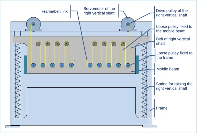
8.1. Principle of moving the beam
The mobile beam is equipped with two rows of loose pulleys (one row per vertical shaft) located in its upper part. The transversal part (between the two lateral sides forming an H) is also equipped with two rows of loose pulleys (one row per vertical shaft) located in its lower part and two drive pulleys (one per shaft) each driven by a servomotor. The pulleys of the frame and beam are linked together by a belt for each shaft driven by the servomotor.
Each of the shafts is equipped with springs that ensure a force in opposition to the lowering of the mobile beam (tool closing).
During the closing movement, the belts are tightened between a fixed point located on the frame and the drive pulley. This draws the pulleys of the beam closer to those of the frame and compresses the springs.
During the opening movement, the belts are loosened and the springs ensure the raising movement of the slide, controlled by the servomotors.
Figure 16: Principle of the pulley/belt drive system
According to the manufacturer and the model of press-brake, the latter can be equipped with two identical pulley/belt drive mechanisms located on either side of the mobile beam. This permits distributing the forces on either side of the beam for high powers.
Likewise for the number and type of springs equipping the vertical shafts. Each of the shafts is equipped with a retention system composed of one or several springs or assemblies of springs assembled in series (end to end). This solution ensures the slide raising function even if a spring breaks.
8.2. Beam stops
The stops can be the same as those described for eccentric drive presses (see § 5.3.2), taking into account that the springs prevent the lowering of the beam by gravity.
9. Safety functions relating to servomotor presses
9.1. Generalities/Introduction
In order to study the influence on safety of the new technologies implemented in servomotor presses, it is first necessary to identify [§ 9.2] and specify [§ 9.3] precisely the safety functions participating in the protection of operators. It is necessary to ensure they are capable of providing the service expected, by taking into account the technologies and principles employed on servomotor presses. For example, the definition of specific and adapted stop functions.
Belt of right vertical shaft
Servomotor of the right vertical shaft
Loose pulley fixed to the frame
Loose pulley fixed to the mobile beam
Spring for raising the right vertical shaft Mobile beam Drive pulley of the right vertical shaft
Frame Frame/belt link
9.2. Identification of functions involved in safety
In conformity with the requirements of the “machinery” directive and in application of the recommendations of standard NF EN ISO 121004, the manufacturer of a servomotor press must carry out a risk assessment, and reduce the risks from the design stage.
Presses, including servomotor presses, generally require human actions in the tool zone (slide movement zone). For example, they take place for setting and maintenance operations, and during certain phases of production such as the manual loading and unloading of parts. Safety measures must therefore be taken to ensure that no slide lowering movement can occur as long as the operator is exposed to a risk in this zone.
In the case of presses, the main safety functions are linked to the protection means (movable guards, protective devices, etc.) intended to cover risks relating to mobile working elements (slide, etc.).
- Mention can be made of stopping and/or hold to stop functions of potentially hazardous mobile elements that stem, for example, from using a movable guard equipped with an interlocking device, an interlocking device with guard locking or a protective device such as photoelectric barriers or a two-hand control.
- There is also a speed limitation function for the hazardous movement when this measure is associated with a hold to run control to reduce risk.
Of the other safety functions specific to presses and for which the use of servomotors requires reflection, mention must be made of the function used to mute the protection means which is authorised when the movement of the mobile element is not in the hazardous phase of a cycle. This is the case in particular when raising the slide (opening tools) of a press. This muting function can only be triggered when the slide is in a “safe” position and/or direction of movement. When the muting function is used, it must be associated with strict control of the slide position and its direction of movement. The latter point is especially important for eccentric drive servomotor presses for which the direction of slide movement is not ensured by the direction of rotation of the servomotor.
9.3. Specification of safety functions
All the safety functions must be specified precisely according to two criteria: - functional requirements,
- safety integrity requirements (e.g., Performance Level required [PLr]).
The functional requirements must permit specifying, among other things, the conditions for activating the function and the description of the action expected from the sensors to the actuators (e.g., stop or movement limitation). If necessary, the specification must specify the type of stop and/or hold to stop expected with the objectives in terms of time/distance of the stop and/or the position of the mobile element considered. Likewise, the movement and speed limitation values must be defined.
The determination of safety integrity requirements is not dealt with in this document. The level of performance required for the safety function (PLr) can be either determined by applying, for example, the methodology proposed in standard NF EN ISO 13849-15, or taken from the press design standard.
In the case of a mechanical servomotor press, Appendix B proposes examples of typical safety function specifications of these presses.
4 NF EN ISO 12100:2010 - Safety of machinery - General principles for design - Risk assessment and risk reduction
5 NF EN ISO 13849-1:2008 - Safety of machinery - Safety related parts of control systems. Part 1: General principles for design
Functional requirements relating to stop and safe hold to stop functions 9.3.1.
It is necessary to foresee and treat safe slide stop functions adapted to each of the potentially hazardous situations. Depending on the protection systems provided and the situations in which they are employed, these stop functions can play several roles. They can be assigned to stopping a movement in progress and/or maintaining a static load, while preventing an unintended start. This requires that different characteristics are taken into account and specified precisely.
By way of example, safety function no. 1 “stop by protective device”, specified in appendix B, requires a “protection stop” function which has two objectives:
- prevent slide movements from occurring as long as the photoelectric barrier is interrupted – this is the “safe” hold to stop function of the slide,
- stop slide movements “covered” by the photoelectric barrier while it is interrupted– it is a stop function triggered during the movement for which the maximum time of completion must be controlled.
To start this stop function, it is necessary to consider that:
the servomotor and its control system (variable speed control ) are integrally involved in the management of stop functions, which is not the case for mechanical presses of traditional design, for which a clutch/brake is used. This assembly can be used actively by adjusting the parameters (torque, speed) for the deceleration phases and also for maintaining the slide stopped;
the slide is a dynamic load subject to gravity that cannot be held in position by the servomotor as it is not powered up;
a mechanical brake is therefore required to ensure the stop phases not guaranteed by the servomotor.
Reminder of the stop categories according to standard EN 60204-1 9.3.2.
NF EN 60204-16 is the only standard to define the stop categories (see Figure 17) for machines. It deals with equipment designed exclusively on the basis of electric technology. As stated previously, the stop functions of servomotor presses use electric components as well as those with other technologies such as hydraulics.
Additional means using non electric technology are needed for stop functions not covered by this standard, and thus not included in the recommendations relating to stop categories, and they must be dealt with additionally by the designer.
Figure 17: Extract of standard EN 60204-1:2006
6 EN 60204-1:2006 - Safety of machinery - Electrical equipment of machines - Part 1: General requirements
The different stop functions of a mechanical servomotor press (eccentric or 9.3.3.
screw drive)
To take into account all the requirements specific to servomotor presses, different hold to stop and stop functions have been defined as a basis for specifications for their safety functions.
9.3.3.1. Safe hold to stop without energy
This is provided to ensure the hold to stop of the slide by doing the following:
o cutting off the electric energy to the servomotor concerned and simultaneously cutting off the power supply (electric or other) to the device maintaining the slide in stopped position (mechanical restraint device).
Note: Safe hold to stop without energy is the last phase of a type 0 safe stop (§ 9.3.3.3) or type 1 (§ 9.3.3.4).
It can also be used:
- to maintain the stop when initiating a “normal stop” (EHSR 1.2.4.1 of directive 2006/42/EC) of a servomotor press whose mobile element was at “safe hold to stop with energy” (§ 9.3.3.2) or “type 2 safe stop” (§ 9.3.3.5),
- to ensure a hold to stop at end of cycle (§ 9.3.3.9).
9.3.3.2. Safe hold to stop with energy
This is provided to ensure the hold to stop of the slide by maintaining the electric power supply to the servomotor concerned.
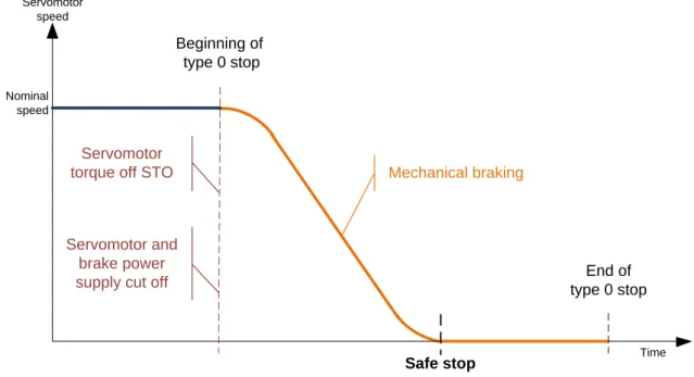
9.3.3.3. Type 0 safe stop
This is provided to ensure the stop of the slide and its hold to stop by doing the following: o Immediate cutting off of the electric power supply to the servomotor
concerned and immediate cutting off of the energy supply (electric or other) to the mechanical brake.
Note: During normal operation, this type of stop can be used to ensure: - a “protection stop” (§ 9.3.3.6),
- an “anti-repetition” (§ 9.3.3.7), - a “stop by control device” (§ 9.3.3.9).
Note: Safe hold to stop with energy constitutes the last phase of a type 2 safe stop (§ 9.3.3.6).
Servomotor speed Time Nominal speed Beginning of type 0 stop Mechanical braking
Stop without energy Hold to stop without energy
End of type 0 stop
Servomotor and brake power supply cut off
Figure 18: Chronogram of the principle of a type 0 safe stop
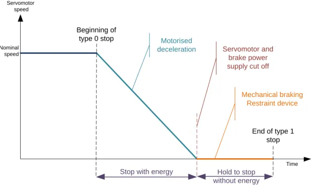
9.3.3.4. Type 1 safe stop
This is provided to ensure the stop of the slide and its hold to stop by doing the following: o decelerate the servomotor by maintaining the electric power supply until the
movement stops,
o then, when the movement stops, cut off the electric power supply to the servomotor and immediately cut off the supply of energy (electric or other) to the mechanical brake.
Note: During normal operation, this type of stop can be used to ensure: - a “protection stop” (§ 9.3.3.6),
- an “anti-repetition” (§ 9.3.3.7), - a “stop by control device” (§ 9.3.3.9).
Servomotor speed Time Nominal speed Beginning of type 0 stop Mechanical braking Restraint device
Stop with energy Hold to stop without energy
End of type 1 stop
Servomotor and brake power supply cut off
Motorised deceleration
Figure 19: Chronogram of the principle of a type 1 safe stop
9.3.3.5. Type 2 safe stop
This is provided to ensure the stop of the slide and its hold to stop by doing the following: o decelerate the servomotor until the movement stops,
o then, when the movement stops, hold to stop.
All this is done while maintaining the electric power supply to the servomotor.
Note: During normal operation, this type of stop can be used to ensure: - a “anti-repetition” (§ 9.3.3.7),
- a “stop by control device” (§ 9.3.3.9).
Servomotor speed Time Nominal speed Beginning of type 2 stop
Motorised hold to stop Hold to stop with energy End of type 2 stop Motorised deceleration Motorised hold to stop
9.3.3.6. Protection stop
Stopping and holding to stop of the slide in reaction to the activation of a protection means (movable guards interlocking device, protective devices such as photoelectric barriers, two-hand controls, etc.) during a hazardous movement, and acting in the form of a type 0 safe stop (§ 9.3.3.3) or a type 1 safe stop (§ 9.3.3.4).
When a stop function (type 0 or 1) is activated in the framework of a protection stop, the control of the stopping time must be ensured, when the slide is stopped, to guarantee the correct positioning of the protection systems in all situations. Control of the stop position must also be ensured during the hold to stop phase to guarantee that the slide does not lower while the operator may be in the hazardous zone.
Note: The notion of the function “Protection stop” (in the draft of the ISO standard), defined previously stems from the works of the standardisation group ISO/TC 39/SC 10/WG. 1, responsible for works on servomotor presses (draft of standard ISO 16092-2).
9.3.3.7. Anti-repetition
When muting function of a protection is activated on an eccentric drive servomotor press during the automatic raising phase, a safety stop must guarantee that the slide is stopped and held to stop at the end of the cycle. This safety function must prevent the cycle from being repeated, leading to a hazardous movement for the operator. This function can be ensured by a type 0 safe stop (§ 9.3.3.3), a type 1 safe stop (§ 9.3.3.4) and type 2 safe stop (§ 9.3.3.5).
When a stop function (type 0, 1 or 2) is implemented in the framework of anti-repetition, control of the stop position must be ensured when stopping the slide and holding the stop, to prevent the slide from lowering after passing through the top dead centre point while the operator is located in the hazardous zone.
Note: For screw presses, hydraulic presses and press brakes, whose kinematics do not allow cycle repetitions in the case of failure, a safety function is not necessary to stop the raising of the slide at the end of the cycle, when the protective device is muted.
However, on these machines, when the stop is obtained normally (not by a safety function), a hold to stop at end of cycle safety function must be implemented when the inhibition of the protection is active.
9.3.3.8. Hold to stop at end of cycle
This safety function guarantees holding the slide to stop in production when the protection device is muted during the planned functional stop, for example, for manual machine loading/unloading operations.
When the protection of a servomotor press (screw, hydraulic or press brake) is ensured by a movable guard without guard locking or protective device, the hold to stop at end of cycle can be ensured by a safe hold to stop without energy (§ 9.3.3.1) or a safe hold to stop with energy (§ 9.3.3.2).
Note: If necessary, this safety function can be ensured by a type 0 safe stop, a type 1 safe stop or a type 2 safe stop which also comprises a hold to stop phase.
When the protection means of a servopress (whatever technology is used) is ensured by a movable guard with an interlockingand guard locking, the hold to stop at end of cycle can be ensured by a safe hold to stop without energy (§ 9.3.3.1). This hold function is required
when the guard is unlocked or not closed, to guarantee the stop of the mobile element and prevent its unintended start-up.
A “safe hold to stop with energy” function can also suffice. However, the advantage for a servomotor press of implementing this (interlocking with guard locking) measure, when not imposed by a problem of movement inertia (stopping time of mobile elements too long to employ an interlocking guard without guard locking) is to override a slide stop safety function with the ensuing material consequences (control of slide stopping time and the need for an adapted braking capacity). Furthermore, since the “safe hold to stop with energy” function requires the supply of energy, in the case of an electric power failure or absence of power, the function can no longer be ensured, meaning that it will be necessary to implement a “safe hold to stop without energy”. In this case, the advantage of choosing a guard equipped with guard locking will be lost.
Recommendation:
When a movable guard with guard locking is considered (see also §11, Analysis of the validity of conventional protection means on servomotor presses
), it is recommended not to
ensure that the slide is held in stopped position by a “safe hold to stop with energy” but to privilege a “safe hold to stop without energy”.When a safe hold to stop function (with or without energy) is implemented in the framework of a hold to end of cycle stop, the control of the stop position must be ensured to guarantee that there is no lowering movement of the slide when the operator is in the hazardous zone.
9.3.3.9. Safe stop by control device
This safety stop ensures that the slide stops and is held to stop when a control device is used (release of the 2nd position or actuation of the 3rd position) and when this measure participates in reducing the risk associated with the reduction of the slide speed. This function can be ensured by a type 0 safe stop (§ 9.3.3.3), and type 1 safe stop (§ 9.3.3.4) or a type 2 safe stop (§ 9.3.3.5).
Note: The current draft of the ISO standard on servomotor presses does not yet define whether a type 2 safe stop can be accepted to ensure this function.
When a stop function (type 0, 1 or 2) is employed in the framework of a stop by control device, control of the stop position must be ensured when holding the slide at stop to ensure that there is no downwards movement of the slide when the operator is in the hazardous zone.
10. Analysis of functions involved in safety
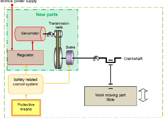
The analysis of the kinematic chain of eccentric drive servomotor presses has led to the identification of the parts (links) involved in the slide downwards movement (hazardous movement), and analyse their functional role. For example, Figure 21 shows the different parts making up the kinematic chain of an eccentric drive servomotor press by highlighting in the green square, the parts that differentiate this type of press from a conventional (clutch/brake) mechanical press.
Figure 21: Example of the kinematic chain of an eccentric drive servomotor press
It is necessary to analyse the behaviour of the components contributing to these safety functions to ensure that they correspond to these specifications during normal operation and in the case of failure. A failure mode and effects analysis (FMEA) must therefore be carried out. Measures must be taken right from the design phase to ensure that none of the links of the chain is defective, whether mechanical, electric or otherwise, and that they cannot dangerously affect the performance of safety functions. Great attention must be given to certain safety functions which, in the case of failure, continue to fulfil their function, but with abnormal characteristics such as longer response times.
This analysis must be conducted according to two criteria:
- functional – to verify that these material parts and the techniques used are capable of ensuring the functions expected,
- functional safety – to characterise their behaviour if a fault occurs in view to identifying those that could cause hazardous situations. To do this, the following points must be analysed for each of the links in the chain and for each of the safety functions considered:
o the type of failure, if necessary the part of the element affected by a potentially hazardous failure and the conditions of its occurrence (type of stop, press cycle phase, etc.),
o the effect on the behaviour of the safety function, o the type of hazard liable to result from this failure,
o the measures to be implemented to react to the failures and prevent hazardous situations from occurring.
Note: Only the parts that include new features in comparison to what is implemented at present on conventional presses are analysed. Indeed, regarding the latter, design recommendations are already included in the standards of the presses concerned.
These new features concern:
- the power drive system related to safety (PDS/SR for Power Drive System / Safety Related as per IEC 61800-5-2), for the instrumentation and control part [§ 10.1],
- and in particular belts and ball screws for the mechanical parts involved in safety [§ 10.10].
The following parts deal with several important points of these analyses regarding different functions or parts of the safety function such as:
- failure mode and effects analysis of the PDS/SR in the framework of applying a stop function,
- the influence of the servomotor’s direction of rotation for eccentric drive presses, - the management of the servomotor’s rotation speed when it contributes to the
implementation of a safety function,
- the analysis of certain mechanical elements of the kinematic chain.
10.1. Analysis of the behaviour of the PDS/SR – All servomotor presses
Generalities 10.1.1.
The power drive system related to safety (PDS/SR) is an essential and unavoidable element of servomotor press control systems and safety functions. It is composed of the servomotor and its control system (including at least an electronic variable speed control and sensors) as shown in Figure 22.
Figure 22: Diagrammatic view of the PDS/SR
The manufacturers of variable speed controllers offer different safety “options” or “modules” to ensure part of the safety functions specified by the press designer. In most cases, these safety “modules” claim conformity with the safety function definitions of standard IEC 61800-5-2 (STO, SS1, SS2, SLS, etc.) which specifies the requirements and gives recommendations for the design, development, integration and validation of the PDS/SR.
The control diagram of a servomotor press incorporating a PDS/SR, can take different forms depending on the level of integration of the safety “modules” offered by the manufacturers and ensuring all or part of the safety functions specified.
Several examples illustrating these different configurations are presented in appendix A.
For certain machines, the PDS/SR can be composed of several servomotors to provide the power required for the slide, or include an energy recovery system. These two specific cases are dealt with in § 10.9.5 to analyse their possible impact on operator safety.
Level of safety of the PDS/SR and behaviour in the presence of a failure 10.1.2.
A PDS/SR must be capable, through its design, to ensure the parts of the safety functions in which it participates, with a Performance Level in accordance with standard NF EN ISO
13849-1 or SIL according to standard NF EN 620617 compatible with the level of risk to be covered.
The manufacturers of variable speed controllers claim safety performance levels for all the “modules” proposed or individually per “module”.
NOTE: Designers of servomotor press control systems must give attention to the fact that these levels of performance are not always easy to find in the manufacturers’ documentation. Moreover, it is not always obvious that when a single global level of performance is claimed, it covers all the “modules” proposed.
Of the different functions (modules) offered by the manufacturers, it must be borne in mind that only the STO function (cf. § 10.2) is capable of ensuring behaviour in the presence of a failure in conformity with its nominal behaviour.
The other safety functions ensure monitoring of the function specified whose reaction, in the case of failure or deviation in comparison to the nominal result expected, lead to a safe fall-back position. This is why the safe fall-fall-back position is characterised by an STO function for these different monitoring functions and in most of the cases observed.This behaviour is the same whatever the safety performance level claimed by the manufacturer of the PDS/SR (level PL or SIL). This safety performance level is in fact assigned to the monitoring function. The entire monitoring system, including the acquisition of information from the sensors (coders) must conform to the performance level specified for the function.
Recommendations:
Generally, and in case of failure, whether following a lack of energy, internal failure or a regulation problem, the reaction to the PDS/SR defect must lead to a fall-back position corresponding to a type 0 safe stop function (§ 9.3.3.3).
This must correspond to the absence of servomotor torque and therefore a fall-back position corresponding to an STO function. Likewise, possible safety outputs on the PDS/SR intended to cut the brake control (to obtain braking) must be designed and programmed to mirror the STO function in all situations.
In the framework of our analysis of the PDS/SR, it is vital to define the role it can play for each type of safety function specified as well as the programming conditions that must be satisfied. It is also necessary to understand its behaviour in the presence of a failure in order to be capable to define adapted safety recommendations.
Note: Failures taken into account at PDS/SR level are those that lead the loss of the safety function required for servomotor presses.
In the framework of stop functions, they can cause the downwards movement of the slide to accelerate instead of decelerate or an unintended downwards movement instead of holding the stop.
For the other safety functions implemented (e.g., speed limitation, control of rotation direction, etc.), they can cause an unintended increase of the downwards movement of the slide or a reversal of the slide movement (transformation of a non-hazardous upwards movement into a potentially hazardous downwards movement).
Implementation of a PDS/SR for safe stop functions 10.1.3.
The stop functions of standard IEC 61800-5-2, which can be used to participate in the functions defined specifically for servomotor presses, are the following:
- STO (Safe Torque Off) – safe absence of torque, - SS1 (Safe Stop 1),
7 NF EN 62061:2005 - Safety of machinery - Functional safety of electric, electronic and programmable electronic control systems related to safety
- SS2 (Safe Stop 2),
- SOS (Safe Operating Stop) – holding to safe stop. The definitions of these functions are available in appendix D.
10.2.
“Safe hold to stop without energy” using an STO function
Functional analysis 10.2.1.
The description of the function is given below:
Reminder: The STO function alone does not hold the slide in stopped position (see NOTE 3 of § 4.2.2.2 of standard IEC 61800-5-2). Thus it must be completed by a mechanical device intended and designed for this purpose.
Recommendations:
Cutting off the supply of energy to the mechanical restraint device must be actuated:
either independently of the PDS/SR, by the same information as that which commanded to the PDS/SR to cut off the energy to the servomotor,
or by using output information from the PDS/SR signalling the cutting off of energy to the servomotor.
Effects of a failure 10.2.2.
In the case of the energy supply being cut off and affecting the entire PDS/SR, and taking into account the reaction to the expected faults (see § 10.1.2), if the power cut occurs when the safe hold to stop function without energy is active:
it remains without energy since the servomotor is not supplied with energy due to the STO function,
it remains without energy since the brake is not powered up.
If the PDS/SR is subject to a failure and taking into account the reaction to faults expected (see § 10.1.2), the reaction of the PDS/SR produces the same effect (a fall-back function in the form of the STO) as the function without failure.
A loss of power supply or a PDS/SR failure does not affect the “safe hold to stop without energy” function.
10.3. Type 0 safe stop function using an STO function
Functional analysis 10.3.1.
The description of this function is given below:
Safe hold to stop using the STO function
Cutting off the electric power supply to the servomotor concerned via an STO function obtained by the PDS/SR and simultaneous cutting off of the supply of energy (electric or other) of the hold to stop device (mechanical restraint system).
Type 0 safe stop using an STO function
Immediate cutting off of the electric power supply to the servomotor concerned via an STO function obtained by the PDS/SR and simultaneous cutting off of the energy (electric or other) to the mechanical brake.