HAL Id: hal-01357553
https://hal.archives-ouvertes.fr/hal-01357553
Submitted on 31 Aug 2016
HAL is a multi-disciplinary open access
archive for the deposit and dissemination of
sci-entific research documents, whether they are
pub-lished or not. The documents may come from
teaching and research institutions in France or
abroad, or from public or private research centers.
L’archive ouverte pluridisciplinaire HAL, est
destinée au dépôt et à la diffusion de documents
scientifiques de niveau recherche, publiés ou non,
émanant des établissements d’enseignement et de
recherche français ou étrangers, des laboratoires
publics ou privés.
Designing a stacked three-element parasitic
superdirective antenna
Abdullah Haskou, Ala Sharaiha, Sylvain Collardey
To cite this version:
Abdullah Haskou, Ala Sharaiha, Sylvain Collardey. Designing a stacked three-element parasitic
su-perdirective antenna. 17th International Symposium on Antenna Technology and Applied
Electro-magnetics, Jul 2016, Montréal, Canada. �10.1109/ANTEM.2016.7550103�. �hal-01357553�
Designing a Stacked Three-Element Parasitic
Superdirective Antenna
Abdullah Haskou, Ala Sharaiha, and Sylvain Collardey
IETR UMR CNRS 6164- Université de Rennes 1, Rennes, France
[email protected], [email protected], [email protected]
Abstract—In this paper we investigate designing a stackedthree-element antenna arrays for UHF band. The array is based on miniaturized printed half-loop antenna integrated in a PCB of 8× 8cm2. To study the inter-element distance effect on the antenna performance (directivity, input impedance and radiation efficiency), a parametric analysis is performed. The obtained results show that for small distances high directivities can be achieved in the case of the fully driven element. However, to transform this array to a parasitic (loaded) one, negative resis-tances are required and neglecting these resisresis-tances significantly decrease the antenna directivity. The results are validated via measurements.
Keywords—Superdirectivity, parasitic-element, directivity, radi-ation efficiency
I. INTRODUCTION
Superdirective antenna arrays satisfy both the
miniaturization- and high directivity- criteria required in most of the modern wireless applications. Since the first practical validation of such arrays by Altshuler et al [1], a considerable research was done in this domain. In analogy to Yagi antenna, early works were based on wire-type antennas [2]-[5]. Recent works are based on printed antennas (due to their attractive characteristics) [6]-[10]. In this paper, we investigate designing a stacked three-element parasitic superdirective antenna array. The main tradeoffs between the antenna directivity, efficiency, and dimensions are detailed.1
II. PROPOSEDANTENNADESIGN
The design methodology of superdirective antenna arrays detailed in [10] was used to develop a three-element array. The unit-element used in this array is a miniaturized half-loop antenna printed on a 0.8mm-thick Rogers RO4003 substrate and integrated in a PCB of 8× 8cm2. It has a simulated
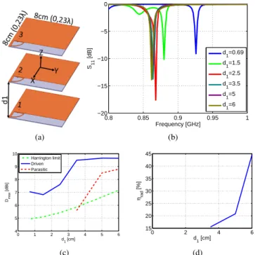
(ANSYS HFSS [11]) resonance frequency around 864M Hz. The antenna size factor is ka = 1, where k = 2π/λ and a is the radius of the smallest sphere enclosing the antenna. The antenna has a directivity of 2.4dBi and radiation efficiency of 89.4%. The proposed antenna geometry is shown in Fig. 1(a). The inter-element distance d1is varied from 0.69cm to 6cm to
investigate its effect on the antenna input reflection coefficient (Fig. 1(b)), maximum directivity (Fig. 1(c)) and radiation efficiency (Fig. 1(d)). For very small distances the antenna resonance is shifted to 926M Hz. As the distance increases this resonance approaches the one of the unit-element. As for
1This work was done with the funding of the French National Research
Agency as part of the project "SOCRATE" and the support of the "Images et Reseaux" cluster of Brittany region, France.
the maximum directivity, we see that starting from an inter-element distance of d1= 3.5cm interesting directivities can be
attained in the case of the fully-driven array. However, in the case of the parasitic array, some negative resistances are re-quired, and neglecting these resistances significantly decreases the attained directivity. As for the parasitic array radiation efficiency, it increases when the inter-element distance exceed 3cm(0.1λ). (a) 0.8 0.85 0.9 0.95 1 −20 −15 −10 −5 0 Frequency [GHz] S11 [dB] d 1=0.69 d 1=1.5 d 1=2.5 d1=3.5 d1=5 d1=6 (b) 0 1 2 3 4 5 6 4 5 6 7 8 9 10 Dmax [dBi] d1 [cm] Harrington limit Driven Parasitic (c) 0 2 4 6 15 20 25 30 35 40 45 ηrad [%] d 1 [cm] (d)
Fig. 1. Proposed array simulated parameters as a function of the inter-element distance. (a) Array geometry, (b) input reflection coefficient magnitude in dB, (c) total directivity and (b) radiation efficiency.
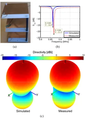
A prototype of the antenna array for d1= 6cm(0.17λ) was
fabricated and measured (Fig. 2(a)). In this array, the second element is excited, the first is short-circuited, while the third one is loaded by 8.3nH. Fig. 2(b) shows the antenna input reflection coefficient magnitude in dB. As it can be noticed, the antenna has a simulated/measured resonance at 863/868M Hz with a S11 < −10dB bandwidth of 1.7/5MHz. The higher
losses in the measurement may be attributed to the UFL cable used in measurement. Fig. 2(c) shows the antenna 3D total directivity radiation pattern. The figure shows a directive pattern with a directivity of 8.8/8.5dBi toward z-axis. This directivity is about 1.4dB greater than Harrington’s normal directivity limit for an antenna with the same size factor
(ka = 1.6) [12]. The HPBW in E (XoZ) and H (YoZ) planes are respectively 72o/73.1o and 64o/67.5o and FBR is 5.8dB/4.1dB (Fig. 3). The antenna presents a radiation efficiency of 34.7%/37%. Finally, Fig. 4 shows that the current on the first and third elements are on phase and they are out of phase compared to the second element. This is the condition for having three-element superdirective arrays with very small spacing. (a) 0.8 0.85 0.9 0.95 1 −25 −20 −15 −10 −5 0 X: 0.863 Y: −16.47 Frequency [MHz] S11 [dB] X: 0.868 Y: −22.15 Simulated Measured (b) Simulated Measured (c)
Fig. 2. Three-element array with 6cm spacing simulated and measured parameters. (a) Fabricated prototype, (b) input reflection coefficient magnitude in dB and (c) 3D total directivity radiation pattern.
−10 0 10 30 210 60 240 90 270 120 300 150 330 180 0 θ [°] Directivity [dBi] Simulated Measured (a) −10 0 10 30 210 60 240 90 270 120 300 150 330 180 0 θ [°] Directivity [dBi] Simulated Measured (b)
Fig. 3. Three-element array with 6cm spacing simulated and measured parameters 2D total directivity radiation patterns. (a) E-plane, (b) H-plane.
III. CONCLUSION
In this paper, we investigated the design of a three-element stacked parasitic antenna array for UHF band. The tradeoffs between the antenna directivity, radiation efficiency, and di-mensions were demonstrated. A prototype was fabricated and measure. The measured results were in a very good agreement with the simulated ones.
1 2 3
Fig. 4. Three-element array with 6cm spacing simulated surface current distribution.
REFERENCES
[1] E. E. Altshuler, T. H. O’Donnell, A.D. Yaghjian, and S. R. Best, "A
Monopole Superdirective Array", IEEE Transactions on Antennas and
Propagation, Vol. 53, No. 8, pp. 2653-2661, August 2005.
[2] T. H. O’Donnell, and A. D. Yaghjian, "Electrically Small Superdirective
Arrays Using Parasitic Elements", IEEE Antennas and Propagation
Society International Symposium 2006, pp. 3111,3114, 9-14 July 2006. [3] T. H. O’Donnell, A. D. Yaghjian, and E. E Altshuler, "Frequency
Optimization of Parasitic Superdirective Two Element Arrays", IEEE
Antennas and Propagation Society International Symposium 2007, pp. 3932,3935, 9-15 June 2007.
[4] S. Lim, and H. Ling, "Design of Electrically Small Yagi Antenna", Electronics Letters, Vol. 43, No. 5, pp. 3-4, 1 March 2007.
[5] A. D. Yaghjian, T. H. O’Donnell, E. E. Altshuler, and S. R. Best
"Electrically Small Supergain End-Fire Arrays", Radio Science, Vol. 43,
2008.
[6] O. S. Kim, S. Pivnenko, and O. Breinbjerg, "Superdirective Magnetic
Dipole Array as a First-Order Probe for Spherical Near-Field An-tenna Measurements", IEEE Transactions on AnAn-tennas and Propagation,
Vol. 60, No. 10, pp. 4670-4676, October 2012.
[7] P. Sharma, D. Arora, and H. Gupta, "Designing Superdirective Patch
An-tenna Array Using Metamaterial", International Journal of Engineering
Research & Technology (IJERT), Vol. 1, Issue 8, October 2012. [8] A. Clemente, M. Pigeon, L. Rudant, and C. Delaveaud, "Design of a
Super Directive Four-Element Compact Antenna Array Using Spherical Wave Expansion, IEEE Transactions on Antennas and Propagation,
vol. 63, no. 11, pp. 4715-4722, November 2015.
[9] A. Haskou, A. Sharaiha, and S. Collardey, "Integrating Superdirective
Electrically Small Antenna Arrays in PCBs", IEEE Antennas and
Wire-less Propagation Letters, doi: 10.1109/LAWP.2015.2425913.
[10] A. Haskou, A. Sharaiha, and S. Collardey, "Design of Small Parasitic
Loaded Superdirective End-Fire Antenna Arrays", IEEE Transactions on
Antennas and Propagation, vol. 63, no. 12, pp. 5456-5464, December 2015.
[11] ANSYS HFSS, Pittsburg, PA 15219, USA.
[12] R. F. Harrington, "On the Gain and Beamwidth of Directional
Anten-nas", IRE Transactions on Antennas and Propagation, pp. 219-225, July