Faculté de génie Département de génie civil
SHEAR STRENGTH AND BEHAVIOR OF
CIRCULAR CONCRETE MEMBERS REINFORCED
WITH FRP BARS AND SPIRALS
Étude du comportement et de la résistance à l’effort tranchant d'éléments
circulaires en béton armé de barres longitudinales et de spirales en matériaux
composites de PRF
Thèse de doctorat Spécialité: Génie civilAhmed Mohammed Hassan Ali
A dissertation submitted in partial fulfillmentof the requirements for the degree of Doctor of Philosophy
Specialty: Civil Engineering
Jury: Prof. Brahim Benmokrane (Directeur de recherche) Prof. Abdeldjélil Bélarbi (Examinateur)
Prof. Ehab El-Salakawy (Examinateur)
Prof. Charles-Philippe Lamarche (Rapporteur) Prof. Richard Gagné (Présidente du jury)
i
ABSTRACT
Circular reinforced concrete (RC) members are often used in civil engineering structures, for instance, as piers and piles in bridge substructures. Also, their applications are frequently utilized as a fender and piling system for harsh water front and marine environments. Such members are usually reinforced with conventional steel bars and stirrups. Corrosion of steel reinforcement constitutes one of the major problems that shorten the lifetime serviceability and, hence, brittle failure of many concrete structures worldwide. In the last decade, the use of fiber reinforced polymer (FRP) materials has been growing to solve some of these problems and increase the anticipated service life of RC structures, such as bridges, parking garages, tunnels, and marine structures. Recently, the use of FRP bars in soft-eyes, which are openings in retaining walls that will be pierced by tunnel boring machines (TBMs), is gaining popularity in the field of tunnel excavation.
In recent years, the shear behavior of RC members reinforced with FRP bars has been the focus of many studies. Accordingly, several codes and design guidelines are available for the design of concrete structures reinforced with FRP bars under shear loads.These codes and design guidelines were developed based on experimental work on rectangular concrete members reinforced with FRP bars and stirrups. Yet, no research seems to have assessed circular concrete members reinforced with FRP bars and spirals under shear loads.
In this research study, an experimental program was designed to investigate the shear behavior of circular members reinforced with glass FRP (GFRP) and carbon FRP (CFRP) bars, and spirals. A total of twenty full-scale circular RC specimens, with a total length 3,000 mm and 500 mm in diameter, were fabricated and tested experimentally under shear load. The specimens were divided to five series; series I contains two reference steel-RC specimens with and without spiral reinforcement. Series II contains three specimens internally reinforced with GFRP longitudinal bars and without spiral
ii
reinforcement. Series III contains five specimens reinforced with GFRP longitudinal bars and spirals (Type I). Series IV includes six specimens reinforced with GFRP bars and spirals (Type II), while series V includes four specimens totally reinforced with CFRP reinforcement. The experimental tests were performed at the structural laboratory, Faculty of Engineering, University of Sherbrooke. The main objective of testing these specimens is to investigate the behavior of circular concrete members reinforced with GFRP or CFRP longitudinal bars and transverse spirals reinforcement. Several parameters have been studied; type of reinforcement, longitudinal reinforcement ratio, shear reinforcement ratio (spiral diameter and spacing), and shear-span-to-depth ratio. The test results of the tested specimens were presented and discussed in terms of load deflection response, crack patterns and modes of failure, ultimate shear capacities, concrete, longitudinal, and spiral strains, effectiveness of FRP spirals, and beam action versus arch action through four journal papers in this dissertation. In addition, an analytical investigation was conducted to evaluate the validity and accuracy of available FRP shear design equations in codes and design guidelines, and to determine whether certain modifications should be introduced in order to make them suitable for circular concrete members reinforced with FRP bars and spirals. The tested specimens were also analysed using Response 2000 (R2K), which is based on the modified compression field theory (MCFT). Based on the finding of this investigation, the shear capacity of FRP-RC members with circular sections may be determined with the approaches developed for rectangular sections provided that certain modifications are made to take into account the effective shear depth, equivalent breadth, the mechanical properties and geometry of GFRP or CFRP spirals. Furthermore, a new equation was introduced to quantify the spirals contribution (Vsf) in circular concrete members to account for FRP spiral
inclination, curvature, and strength reduction as a result of the stretching process. The proposed equation provided more reasonably accurate predictions.
iii
RÉSUMÉ
Les éléments circulaires en béton armé sont largement utilisés dans les structures en génie civil, comme par exemple, les pieux et les piles de pont. Également, ils sont très utilisés dans les systèmes de pieux battus dans des environnements agressifs et marines. Ces éléments sont habituellement utilisés avec un renforcement interne en acier. La corrosion de l'acier est un des problèmes majeurs qui diminuent la durée de vie et peuvent même amener la structure à la ruine et ce, partout dans le monde. Dans la dernière décennie, utiliser des polymères renforcés de fibres (PRF) est une bonne solution aux problèmes précédents et augmente la durée de vie des structures en béton armé, comme les ponts, les stationnements, les tunnels et les structures marines. Récemment, l'utilisation des barres de PRF dans les murs-diaphragmes, qui sont des ouvertures dans les murs de soutènement percé avec de la machinerie d'excavation de tunnel, gagne en popularité dans le domaine de l'excavation de tunnel.
Depuis quelques années, le comportement en cisaillement des éléments en béton armé de PRF a été étudié dans plusieurs recherches. Par conséquent, les normes et les guides de dimensionnement sont disponibles pour les efforts tranchants. Ils sont développés à partir des expériences en laboratoires sur des éléments rectangulaires. Par contre, aucune recherche a été fait sur les éléments circulaires renforcés de PRF avec des barres et des spirales sous un effort tranchant.
Dans ce sujet d'étude, un programme expérimental a été développé pour regarder le comportement en cisaillement des éléments circulaires en béton armé de PRV de verre (PRFV) et de PRF de carbone (PRFC), pour les barres longitudinales ainsi que pour les spirales (transversales). Un total de 20 spécimens circulaire de grandeur réelle, avec comme dimension 3,000 mm de long et 500 mm de diamètre, ont été fabriqués et testés à l'effort tranchant. Les spécimens ont été divisés en cinq séries; la série I contient deux spécimens de références en acier avec et sans renforcement transversal. La série II contient trois spécimens ayant de l'armature longitudinale en PRFV avec et sans
iv
renforcement transversal. La série III contient cinq spécimens renforcés de PRFV (Type I) dans le sens longitudinal et transversal. La série IV comprend six spécimens renforcés de PRFV (Type II) dans le sens longitudinal et transversal. Finalement, la série V comprend quatre spécimens totalement renforcés de PRFC. Les essais expérimentaux ont été réalisés dans le laboratoire de structure de la Faculté de génie à l'Université de Sherbrooke. L'objectif principal est de tester ces spécimens pour étudier le comportement des poutres circulaires en béton armé avec des PRFV et PRFC pour le renforcement longitudinal et transversal (spiral). Plusieurs paramètres y sont étudiés : type de renforcement, le taux d'armature longitudinal, le taux d'armature en cisaillement (diamètre et espacement des spires) ainsi que le rapport portée en cisaillement sur la profondeur effective. Les résultats sur les spécimens sont présentés et discutés en terme de la flèche, du réseau de fissuration, du mode de rupture, de la capacité ultime en cisaillement, le béton, la déformation longitudinale et transversale, efficacité des spirales en PRF, l'action de poutre à arche sur quatre articles de journal discutés dans cette dissertation, une étude analytique pour évaluer la validité des équations disponibles dans les codes et les guides de dimensionnement et de déterminer si certaines modifications devraient être faites pour que les sections circulaires avec un renforcement complet avec des spirales en PRF soient mieux adaptées. Les poutres testées ont également été analysées en utilisant Response 2000 (R2K), où il est basé sur la théorie du champ de compression modifiée (TCCM). Basé sur les résultats obtenus, la capacité en cisaillement des éléments circulaires en béton armé de PRF a été déterminé avec l'approche d'une section rectangulaire mais en changeant certains paramètres pour prendre en compte la profondeur effective, la largeur équivalente, des propriétés mécaniques ainsi que la géométrie des PRFV et PRFC pour les spirales. De plus, une nouvelle équation est introduite pour quantifier la contribution des spirales (Vsf) des éléments circulaires pour
prendre en considération l'inclinaison des spires, de la courbure et de la réduction de la résistance suite à l'étirement de la spirale. L'équation proposée permet de prédire raisonnablement la capacité en cisaillement.
v
BIBLIOGRAPHY
During the research work at the University of Sherbrooke, the candidate has participated in the following publications related papers and reports that have been published:
Journal Papers
1. Ali, A. H., Mohamed H., and Benmokrane, B. (2016). ―Strength and Behavior of Circular FRP-Reinforced Concrete Sections without Web Reinforcement in Shear.‖ Journal of Engineering Structural, ASCE. Published 2016.
2. Ali, A. H., Mohamed H., and Benmokrane, B. (2015). ―Shear Strength of Circular Concrete Beams Reinforced with Glass FRP Bars and Spirals.‖ ACI Structural Journal. 19th, 2015, (#S-2015-202). In peer review.
3. Ali, A. H., Mohamed H., and Benmokrane, B. (2016). ―Shear Behavior of Circular Concrete Members Reinforced with GFRP Bars and Spirals at Shear-Span-to-Depth Ratios between 1.5 and 3.0.‖ Journal of Composites for Construction, ACSE. Published 2016.
4. Mohamed H., Ali, A. H., and Benmokrane, B. (2016). ―Behavior of Circular Concrete Members Reinforced with Carbon-FRP Bars and Spirals under Shear.‖ Journal of Composites for Construction, ACSE. Accepted 2016.
5. Mohamed H., Ali, A. H., and Benmokrane B. (2016). ―Shear Strength Contribution of FRP Discrete Hoops and Continuous Spirals in Circular Concrete Members.‖ Journal of Bridge Engineering, ACSE. Submitted April, 2016.
6. Ali, A. H., Mohamed H., and Benmokrane, B. (2016). ―Evaluation of Shear Section Models and Plasticity Approach for Design of Circular FRP Reinforced Concrete Members.‖ Engineering Structures, ElSEVIER. Submitted April, 2016. Refereed Conferences Publications
7. Ali, A. H., Mohamed H., and Benmokrane, B. )2013(. ―Shear Resistance of Circular Concrete Members Reinforced with FRP Bars: Code Predictions and
vi
Numerical Analysis.‖ 3rd Specialty Conference on Engineering Mechanics and Materials, CSCE Annual Conference, 29 May- 1 June 2013.
8. Ali, A. H., Mohamed H., and Benmokrane, B. )2016(. ―Shear Strength of Circular Concrete Beams Reinforced with GFRP Bars.‖ 5th International Structural Specialty Conference, CSCE Annual Conference, London, Canada, 1-4 June 2016. 9. Ali, A. H., Mohamed H., and Benmokrane, B. )2016(. ―Concrete Contribution to
Shear Resistance of Circular Concrete Piles Reinforced With GFRP Bars.‖ 7th International Conference on Advanced Composite Materials in Bridges and Structures, Vancouver, British Columbia, Canada, 24 – 26 August 2016 / 24. 10. Ali, A. H., Mohamed H., and Benmokrane, B. )2016(. ―Shear Performance of RC
Piles Reinforced With Glass FRP Bars and Spirals.‖ 7th International Conference on Advanced Composite Materials in Bridges and Structures, Vancouver, British Columbia, Canada, 24 – 26 August 2016 / 24.
Refereed Journal Papers
11. Benmokrane, B., Ali, A. H., Mohamed, H., Robert, M., and ElSafty, A. )2015(. ―Durability Performance and Service Life of CFCC Tendons Exposed to Elevated Temperature and Alkaline Environment.‖ Journal of Composites for Construction, 20(1), 04015043.
12. Benmokrane, B., Robert, M., Mohamed H., Ali, A. H., and Cousin, P. (2016). ―Durability Assessment of GFRP Bars Used for Ground Control in Jurong Rock Caverns-Singapore in Simulated Field Condition.‖ Journal of Composites for Construction, ACSE. Published, 2016.
13. Benmokrane, B., Ali, A. H., and Mohamed, H. (2016). ―Laboratory Characterization and Durability Performance of Vinylester, Poylester, and Epoxy Glass-FRP Bars.‖ Journal of Composite for Construction, ACSE. Submitted on Apirl, 2016.
14. Ahmed H. Ali, Mohammad Z. Afifi, Bahira Abdulsalam, Hesham Haggag, Awad El Hashimy, Tarek El-Sayed, and Hamdy M. Mohamed (2014). ―Performance
vii
Evaluation of One-Way Concrete Slabs Reinforced with New Developed GFRP Bars.‖ Materails Science and Application, Vol. (6), 420-435.
15. Bahira Abdulsalam, and Ahmed H. Ali (2014). ―The Preservation of Historical Masonry Heritage Structures using Advanced Composite Materials.‖ International Journal of Engineering Sciences and Research Technology, 4(8), 14-24.
16. Ahmed H. Ali, Awad El hashimy, Hesham Haggag, and Tarek El-Sayed (2015). ―Physical, Mechanical, and Durability Performance of GFRP Square Reinforcing Bars Exposed to Alkaline Solution.‖ International Journal of Engineering Sciences and Research Technology, 4(6), 548-553.
17. Ahmed H. Ali, Bahira Abdulsalam, Hamdy M. Mohamed, and Mohammad Z. Afifi (2015). ―Enhancing the behaviour of FRP RC Slabs using Square FRP Bars and Fiber Concrete.‖ International Journal of Civil and Structural Engineering, 6(1), 70-90.
Refereed Conference Publications:
18. Ahmed, H. Ali, Hamdy, M. Mohamed, Patrice Cousin, Adel Elsafty, and Brahim Benmokrane (2015). ―Physical, Mechanical, and Durability Characterization of Carbon FRP Cable.‖ 3th Conference on Smart Monitoring, Assessment and Rehabilitation of Civil Structures (SMAR), 7-10th September 2015, Istanbul, Turkey.
19. Ahmed, H. Ali, Hamdy M. Mohamed, Adel ElSafty, and Brahim Benmokrane (2015). ―Long-Term Durability Testing of Tokyo Rope Carbon Cables.‖ 20th International Conference on Composite Materials Copenhagen, 19-24th July 2015, Denamark.
20. Brahim Benmokrane, Ahmed, H. Ali, Hamdy M. Mohamed, and Adel ElSafty (2015). ―Durability of Tokyo Rope Carbon Cables in Alkaline Environment.‖ 7th International Conference on FRP Composites in Civil Engineering International Institute for FRP in Construction, 22-24th August, 2015, Vancouver.
viii
21. Brahim Benmokrane, Ahmed, H. Ali, H M Mohamed, and Adel El Safty (2015). ―Long-Term Tensile Properties of Carbon FRP Cable.‖ 15th International European Bridge Conference, London, UK 8-10th, July 2014.
22. Brahim Benmokrane, A. H. Ali, H. M. Mohamed, and M. Robert (2016). ―Mechanical and Durability Characteristics of Glass-FRP Bars with Different Types or Resins.‖ 7th International Conference on Advanced Composite Materials in Bridges and Structures, Vancouver, British Columbia, Canada, 24 – 26 August 2016 / 24.
Posters:
23. Ali, A. H., Mohamed H.M, and Benmokrane, B. (2015). ―Shear Strength of Circular FRP-Reinforced Concrete Beams.‖ NSERC Annual meeting, Sherbrooke, Canada, June 2015.
24. Ali, A. H., Mohamed H.M, and Benmokrane, B. (2015). ―Durability of Tokyo Rope Carbon Cables in Alkaline Solution and subjected to Extreme Temperatures.‖ NSERC Annual meeting, Sherbrooke, Canada, June 2015.
25. Ali, A. H., Mohamed H.M, and Benmokrane, B. (2015). ―Effect of Shear-Span-to-Depth Ratio on Shear Behavior of Circular RC Members.‖ Student meeting CRIB, Quebec City, Sherbrooke University, Canada, June 2015.
26. Ali, A. H., Mohamed H.M, and Benmokrane, B. (2014). ―Shear Behavior of Full-Scale FRP Circular Reinforced Concrete Beams as Pile Application.‖ Student meeting CRIB, Quebec City, Laval University, Canada, August 2014.
Also, the candidate has participated in the following related reports that have been published:
Technical Reports
27. Ali, A. H., Mohamed H., Benmokrane, B., and ElSafty, A. )2015(. ―Degradation Mechanisms of GFRP Rebar in Concrete and Testing Protocol Previously used To
ix
Evaluate The service Life of FRP Reinforcements in Concrete Based on Degradation Mechanisms.‖ Technical Report, October 10th.
28. Ali, A. H., Mohamed H., Benmokrane, B., and ElSafty, A. )2015(. ―Quantifying Degradation of CFCC under Sustained Tensile Loading in High Alkaline Environment and Elevated Temperatures.‖ Technical Report, November 2nd.
29. Ali, A. H., Mohamed H., and Benmokrane, B. (2015). ―Circular Concrete Beams Reinforced with FRP Reinforcement under Shear Load.‖ NSERC Industrial Research Chair in Innovative Fibre Reinforced Polymer (FRP) Composite Materials for Infrastructure, Technical Report.
30. Ali, A. H., Mohamed H., and Benmokrane, B. (2014). ―Flexural Properties of Polyester and Epoxy Glass Fibre-Reinforced Polymer Bars of Size 12 mm: Reference, 1000-h, Alkaline Conditioned Specimens.‖ Technical Report. September 11th.
31. Ali, A. H., Mohamed H., and Benmokrane, B. (2014). ―Long-term strength prediction of Polyester and Epoxy Glass Fibre-Reinforced Polymer Bars of Size 12 mm: Reference, 1000-hr, 3000 and 5000-hr Alkaline Conditioned Specimens.‖ Technical Report. June, 18p.
32. Ali, A. H., Mohamed H., and Benmokrane, B. (2013). ―Long-Term Performance of CFCC Tokyo Rope under Alkaline Conditioning: Reference, 1000-hr, 3000-hr, 5000, and 7000-hr Alkaline Conditioned Specimens.‖ Technical Report, July, 53p 33. Ali, A. H., Mohamed H., and Benmokrane, B. (2013). ―Long-Term long
Durability of Tubular and Solid GFRP Bars: Reference, 1000-hr, 3000-hr, and 5000-hr Alkaline Conditioned Specimens.‖ Technical Report, June, 21 p.
34. Ali, A. H., Mohamed H., and Benmokrane, B. (2013). ―Interlaminar Shear Strength of Vinylester, Polyester and Epoxy Glass Fibre-Reinforced Polymer Bars of Size 12 mm: Reference, 1000-hr, 3000 and 5000-hr Alkaline Conditioned Specimens.‖ Technical Report, September, 20 p.
35. Ali, A. H., Mohamed H., and Benmokrane, B. (2013). ―Tensile Properties of Polyester and Epoxy Glass Fibre-Reinforced Polymer Bars of Size 12 mm:
x
Reference, 1000-hr, 3000 and 5000-hr Alkaline Conditioned Specimens.‖ Technical Report. October, 28 p.
36. Ali, A. H., and Benmokrane, B. (2013).The Effect of Harsh Enviromental on Long-Term Performance of Internal and External FRP Reinforcement under Sustained Load.‖ Technical Report. March, 33p.
xi
ACKNOWLEDGEMENTS
I would like to express my sincere and profound gratitude to my supervisor Professor Brahim Benmokrane for offering me the opportunity to work on such a challenging subject. I am so proud to work with him. All of the guidance, insight, helpful advice, and constant encouragement provided throughout the course of the dissertation are greatly appreciated. I owe him an unbelievable amount of gratitude for his prominent role in helping me to achieve one of the greatest accomplishments in my life.
I am deeply grateful indebted to Dr. Hamdy Mohamed for his constant cooperation, continuous encouragement, consulting, guidance, and friendship not only on the academic side but also on the personal level.
I would like to thank the structural laboratory technical staff at the Structures Laboratory, Department of Civil Engineering at the Université de Sherbrooke, especially, Mr., Simon Kelly and Martin Bernard for their technical assistance during the fabrication, construction and testing of the specimens.
Also, we are thankful to Natural Science and Engineering Research Council of Canada (NSERC) and the Fonds québécois de la recherche sur la nature et les technologies (FQRNT) for their financial support; Pultrall Inc. (Thetford Mines, Quebec) for their donation of the FRP materials, and the University of Sherbrooke is greatly acknowledged for supporting this research.
Many thanks also go to all my colleagues and friends at the Université de Sherbrooke. Their friendliness streamlined and supported my studies and life style during the period of my doctoral studies.
I cannot end my acknowledgements without expressing my deep appreciation and thanks to: my brother and sisters from the bottom of my heart for their support, endless love and encouragement. Finally, I owe my loving thanks and deep love and appreciation to my wife for her steadfast support and continuously encouraged me throughout these years. She was always there to give me the push for this challenge. I cannot present this work without expressing my love to my children Eyad and Adam who enlightened my life with their smile; to them this thesis is dedicated.
xii
Dedication
To the researchers and engineers who appreciate the value of science and
knowledge.
To the memory of my father and mother
To my mother and father in law
To my brother and sisters whom always give their patience, support,
encouragement, and extensive supports at important times of my life.
To my lovely wife who always supports me and understands my special
circumstances as a researcher.
To my Children Eyad and Adam who come to the existence during my
doctorate and has made a big difference to my life.
xiii
TABLE OF CONTENTS
ABSTRACT ... i RÉSUMÉ ... iii BIBLIOGRAPHY ... v ACKNOWLEDGEMENTS ... xiTABLE OF CONTENTS ... xiii
LIST OF FIGURES ... xxiii
LIST OF TABLES ... xxxi
NOTATIONS ... xxxiii
CHAPTER 1 INTRODUCTION ... 1
1.1 Back Ground and Problem Definition ... 1
1.2 Research Significance ... 3
1.3 Research Objectives ... 4
1.4 Methodology ... 5
1.5 Structure of the Dissertation ... 6
CHAPTER 2 LITERATURE REVIEW ... 9
2.1 General ... 9
2.2 Shear Transfer Mechanisms of Concrete Members ... 9
xiv
2.2.2 Interlocking Action of Aggregate ... 10
2.2.3 Dowel Action of Longitudinal Reinforcing Bars ... 12
2.2.4 Arch Action ... 13
2.2.5 Residual Tensile Stresses ... 13
2.3 Modes of Shear Failure and Influencing Parameters ... 14
2.3.1 Shear Failure for Members without Shear Reinforcement ... 14
2.3.2 Shear Failure for Members with Shear Reinforcement ... 20
2.4 Fibre Reinforced Polymer Composite Material ... 21
2.4.1 Mechanical Properties of FRP Reinforcing Bars ... 23
2.4.1.1 Axial Tensile Strength ... 23
2.4.1.2 Compressive Strength ... 23
2.4.1.3 Shear Strength ... 26
2.4.1.4 Bond Strength (Pull-out Test) ... 27
2.4.1.5 Bend Portion Strength ... 28
2.5 Shear Behavior of FRP Reinforced Concrete Members with Rectangular Cross Section ... 31
2.5.1 Members without Shear Reinforcement ... 31
2.5.2 Members with Shear Reinforcement ... 37
xv
2.6.1 Introduction ... 43
2.6.2 Geometry ... 44
2.6.3 Efficiency of Hoops and Spirals Reinforcement ... 45
2.6.4 Previous Work on Circular Reinforced Concrete Members ... 48
2.7 Shear Design Provisions for FRP-Reinforced Concrete Members ... 51
2.7.1 ACI 440.1R-15 Design Guidelines ... 51
2.7.2 Canadian Standard Code CAN/CSA-S806-12 ... 52
2.7.3 Canadian Standard Code CAN/CSA-S6-14 ... 54
2.7.4 JSCE Shear Design Method ... 56
CHAPTER 3 RESEARCH PROGRAM ... 59
3.1 General ... 59
3.2 Experimental Research Program ... 59
3.2.1 Introduction ... 59 3.2.2 Material Properties ... 60 3.2.2.1 Concrete ... 60 3.2.2.2 Steel Reinforcement ... 60 3.2.2.3 GFRP Reinforcement ... 60 3.2.2.4 CFRP Reinforcement ... 61
xvi
3.2.4 Fabrication of Test Specimens ... 68
3.2.5 Instrumentations ... 73
3.2.6 Test Set-up and Procedure ... 74
CHAPTER 4 STRENGTH AND BEHAVIOR OF CIRCULAR FRP-REINFORCED CONCRETE SECTION WITHOUT WEB REINFORCEMENT IN SHEAR ... 77 4.1 Preface ... 77 4.1.1 Journal ... 77 4.1.2 Contribution in thesis: ... 77 4.2 Abstract ... 77 4.3 Introduction ... 78
4.1 Research on Concrete Contribution to the Shear Resistance of FRP-Reinforced Members ... 79
4.2 Research on the Shear Strength of Circular RC Members ... 81
4.3 Research Significance ... 82
4.4 Test Program ... 83
4.4.1 Specimen Design ... 83
4.4.1 Material Properties ... 84
4.4.2 Specimen Fabrication Details ... 86
xvii
4.5 Experimental Test Results and Discussion ... 88
4.5.1 Effect of Test Parameters on Load–Deflection Behavior ... 89
4.5.2 Crack Pattern and Modes of Failure ... 90
4.5.3 Strains in the Longitudinal Reinforcement ... 95
4.5.4 Concrete Strain ... 96
4.5.5 Shear Strength ... 99
4.5.6 Shear Crack Width ... 100
4.6 Design Provisions for Calculating Vcf in FRP-Reinforced-Concrete Members 102 4.6.1 ACI 440.1R-15 Design Guidelines ... 103
4.6.2 Canadian Standard Code CAN/CSA-S806-12 ... 103
4.6.3 Canadian Standard Code CAN/CSA-S6-14 ... 104
4.6.4 JSCE Shear Design Method ... 105
4.6.5 BISE Design Guidelines ... 105
4.7 Shear Design Provisions for Circular Members ... 106
4.8 Comparison of Codes, Design Guidelines, and Other Available Shear Design Methods with the Experimental Results ... 108
4.9 Conclusion ... 114
CHAPTER 5 SHEAR STRENGTH OF CIRCULAR CONCRETE BEAMS REINFORCED WITH GLASS-FRP BARS AND SPIRALS ... 117
xviii 5.1 Preface ... 117 5.1.1 Journal ... 117 5.1.2 Contribution in thesis: ... 117 5.2 Abstract ... 117 5.3 Introduction ... 118 5.4 Research Significance ... 121 5.5 Experiments ... 122 5.5.1 Specimen Details ... 122 5.5.2 Materials ... 124
5.5.1 Instrumentation and Test Setup ... 124
5.6 Test Results and Discussion ... 126
5.6.1 Effect of Test Parameters on Load–Deflection Response ... 126
5.6.2 Crack Pattern and Modes of Failure ... 129
5.6.1 Mid-Span Flexural Strains ... 130
5.6.2 Strain in the GFRP Spirals ... 134
5.6.3 Shear Strength ... 135
5.6.4 Contribution of GFRP Spirals ... 136
5.7 Shear Strength Predictions and Comparison with Experimental Results ... 139
xix
CHAPTER 6 SHEAR BEHAVIOR OF CIRCULAR CONCRETE MEMBERS REINFORCED WITH GFRP BARS AND SPIRALS AT
SHEAR-SPAN-TO-DEPTH RATIOS BETWEEN 1.5 AND 3.0 ... 147
6.1 Preface ... 147 6.1.1 Journal ... 147 6.1.2 Contribution in thesis: ... 147 6.2 Abstract ... 147 6.3 Introduction ... 148 6.4 Experimental Investigation ... 152 6.4.1 Material ... 152
6.4.2 Details of Test Specimens ... 153
6.4.3 Instrumentation and Test Setup ... 157
6.5 Experimental Results and Discussion ... 157
6.5.1 Effect of Spiral Reinforcement Ratio on Load–Deflection Behavior ... 158
6.5.2 Effect of shear span to depth ratio on Load–Deflection Behavior ... 160
6.5.3 Crack Patterns and Modes of Failure ... 161
6.5.4 Load–Flexural-Tension-Strain Relationship ... 167
6.5.5 Concrete Strains ... 167
6.5.6 Strain in GFRP Spirals ... 169
xx
6.5.8 Beam Action versus Arch Action ... 172 6.6 Theoretical Shear Strength ... 175 6.6.1 Sectional Models ... 175 6.6.2 Strut-and-Tie Model ... 178 6.6.3 Shear Strength Predication Using Modified Comparison Field Theory (MCFT) 181
6.7 Conclusions ... 183
CHAPTER 7 BEHAVIOR OF CIRCULAR CONCRETE MEMBERS REINFORCED WITH CARBON FRP BARS AND SPIRALS UNDER SHEAR . 185
7.1 Preface ... 185 7.1.1 Journal ... 185 7.1.2 Contribution in thesis: ... 185 7.2 Abstract ... 185 7.3 Introduction ... 186 7.4 A review on Shear Behavior of Circular RC Members ... 188 7.5 Experimental Work ... 192 7.5.1 Carbon FRP bars and Spirals ... 192 7.5.2 Steel Reinforcement ... 192 7.5.3 Test Matrix and Specimen Preparation ... 192 7.5.4 Specimen Fabrication Details ... 194
xxi
7.5.5 Instrumentation and Test Setup ... 196 7.6 Test Results and Discussion ... 197 7.6.1 Effect of Test Parameters on Load–Deflection Response ... 197 7.6.2 Crack Pattern and Modes of Failure ... 200 7.6.3 Mid-Span Reinforcement Strains ... 203 7.6.4 Concrete Strain ... 204 7.6.5 Strain in the CFRP Spirals ... 206 7.6.6 Shear Strength ... 207 7.6.7 Efficiency of CFRP Spirals ... 208 7.7 Shear Strength Predictions and Comparison with Experimental Results ... 211 7.8 Conclusions ... 216
CHAPTER 8 SUMMARY, CONCLUSIONS, AND RECOMMENDATION FOR FUTURE WORK ... 219
8.1 Summary ... 219 8.2 Conclusions ... 220 8.2.1 Members without Web Reinforcement ... 220 8.2.2 Members with GFRP Spiral Reinforcement ... 222 8.2.3 Members with Different Shear-Span-to-Depth Ratio ... 224 8.2.4 Members with CFRP Spiral Reinforcement ... 225
xxii
8.3 Recommendations for Future Work ... 226 8.4 Impact of Current Research ... 227 Résumé, conclusions, et recommandation pour des travaux futurs ... 228 Poutres sans renforcement de l’âme ... 228 Poutres avec un renforcement de PRFV en spirale ... 229 Poutres avec différent ratio de portée de cisaillement à la profondeur ... 231 Poutres avec un renforcement de PRFC en spirale ... 233
REFERENCES ... 237 APPENDIX (A) ... 253 APPENDIX (B) ... 256
xxiii
LIST OF FIGURES
Figure 2-1: Shear transfer actions in a cracked reinforced concrete member ... 11
Figure 2-2: Transmission of shear stresses by aggregate interlock (Vecchio and Collins 1986) ... 12
Figure 2-3: Arch action in a reinforced concrete member (Kotsovos and Lefas 1990) .. 13
Figure 2-4: Types of inclined cracks ... 14
Figure 2-5: Effect of shear span to depth ratio (a/d) on shear strength of beams without stirrups (MacGregor 1997( ... 15
Figure 2-6: Modes of shear failures in deep beams (ASCE-ACI Committee 426, 1973) 16
Figure 2-7: Modes of shear failures in short beams (ASCE-ACI Committee 426, 1973) 17
Figure 2-8: Diagonal tension failure (ASCE-ACI Committee 426, 1973) ... 17
Figure 2-9: Effect of reinforcement ratio on shear capacity of beams without stirrups (ACI-ASCE Committee 326 Report 1962) ... 19
Figure 2-10: Basic material components of FRP composite ... 22
Figure 2-11: Different types of FRP bars ... 22
Figure 2-12: Anchor length according to ASTM D7205/D7205M-11 (2011) ... 24
Figure 2-13: Schematic drawing of pull-out test (B.3) ... 28
Figure 2-14: Schematic drawing for B.5 test (Ahmed et al. 2010) ... 30
Figure 2-15: Circular spirals and hoops shear reinforcement geometry (Feltham 2004)
xxiv
Figure 2-16: Circular spirals and hoops shear reinforcement geometry ... 45
Figure 3-1: GFRP bars ... 61
Figure 3-2: GFRP spirals ... 61
Figure 3-3: CFRP spirals ... 63
Figure 3-4: CFRP bars ... 63
Figure 3-5: Reinforcement details of specimens without shear reinforcement ... 66
Figure 3-6: Reinforcement details of specimens with GFRP and CFRP spiral reinforcement ... 66
Figure 3-7: Reinforcement details of specimens (series IV) with GFRP spiral reinforcement ... 68
Figure 3-8: Overview of the GFRP cages ... 69
Figure 3-9: Overview of the CFRP cages ... 70
Figure 3-10: Overview for cages inside cardboard tube ... 70
Figure 3-11: Overview of the formwork ... 71
Figure 3-12: Casting specimens ... 72
Figure 3-13: Specimens after casting ... 72
Figure 3-14: Handling of specimens ... 73
Figure 3-15: Instrumentations of test circular specimens ... 74
Figure 3-16: Location of crack measurement using LVDTs ... 74
xxv
Figure 3-18: Photograph of test setup ... 76
Figure 4-1: GFRP soft-eyes in tunnel applications ... 80
Figure 4-2: Reinforcement details and dimensions of the circular RC specimens ... 84
Figure 4-3: Fabrication and preparation of the circular specimens: (a) overview of the assembled FRP cages; (b) FRP cages inside the cardboard tubes; (c) formwork; (d) circular specimens ... 87
Figure 4-4: Test setup ... 88
Figure 4-5: Load–deflection relationship ... 92
Figure 4-6: Failure mode of the steel-RC specimen ... 93
Figure 4-7: Failure mode of the CFRP-RC specimen ... 93
Figure 4-8: Failure mode of the GFRP-RC specimens ... 94
Figure 4-9: Crack patterns of the test specimens at failure ... 95
Figure 4-10: Load–strain relationship for the reinforcement ... 96
Figure 4-11: Load–strain relationship for the concrete at mid-span ... 98
Figure 4-12: Load–strain relationship for concrete strain at mid shear span ... 99
Figure 4-13: Normalized shear strength versus reinforcement ratio ... 101
Figure 4-14: Normalized shear strength versus the flexural stiffness of the reinforcing bars ... 101
Figure 4-15: Load–shear-crack-width relationship ... 102
xxvi
Figure 5-1: Illustration of terms bw, dv, and d for circular sections. ... 121
Figure 5-2: Dimensions and reinforcement details of the test specimens. (dimensions in mm) (Note: 1 mm = 0.0394 in.) ... 123
Figure 5-3: Fabrication and preparation of the circular specimens: (a) overview of the assembled GFRP cages; (b) circular specimens. ... 126
Figure 5-4: Load-deflection relationship for effect of reinforcement type (Note: 1 mm = 0.0394 in.; 1 kN = 0.225 kips... 128
Figure 5-5: Load-deflection relationship for effect of #4 spiral spacing (Note: 1 mm = 0.0394 in.; 1 kN = 0.225 kips.) ... 129
Figure 5-6: Load-deflection relationship for effect of #5 spiral spacing (Note: 1 mm = 0.0394 in.; 1 kN = 0.225 kips.) ... 129
Figure 5-7: Cracking pattern at failure. ... 131
Figure 5-8: Cracking appearance of test specimen at different loading stages: (a)
specimen with no spiral (BG); (b) immediately before GFRP-spiral rupture (BG4-200); (c) immediately before GFRP-spiral rupture (BG4-100); (d) after GFRP-spiral rupture and removing the concrete cover (BG4-100). ... 132
Figure 5-9: Load–flexural-tension-strain relationship at mid-span. (Note: 1 kN = 0.225 kips.) ... 133
Figure 5-10: Load–concrete-strain relationship at mid-span. (Note: 1 kN = 0.225 kips.)
... 133
Figure 5-11: Load–spiral-strain relationship at shear span. (Note: 1 kN = 0.225 kips.)
xxvii
Figure 5-12: Effect of spiral-reinforcement ratio on shear strength. (Note: 1 kN = 0.225 kips.) ... 136
Figure 5-13: Shear across a circular section. ... 137
Figure 5-14: Effect of spiral-reinforcement ratio on the effective shear stress of GFRP spirals. ... 139
Figure 5-15: Experimental and predicted components of shear resistance. (Note: 1 kN = 0.225 kips.; 1 MPa = 0.145 ksi.) ... 144
Figure 6-1: GFRP bars and spirals ... 153
Figure 6-2: Dimensions and reinforcement details of test circular specimens ... 155
Figure 6-3: Fabrication and preparation of specimens: (a) overview of the assembled GFRP cages; (b) steel formwork and Sonotubes; (c) circular specimens ... 156
Figure 6-4: Instrumentations and test set-up ... 158
Figure 6-5: Load-deflection response at mid-span for the effect of spiral reinforcement ratio ... 159
Figure 6-6: Load-deflection response at mid-span for the effect of shear span-to-depth ratio ... 161
Figure 6-7: Crack patterns of tested specimens ... 164
Figure 6-8: Failure mode of specimen B3.0-S0.35 (a/d=3) ... 165
Figure 6-9: Crack propagation and failure mechanism (a/d =2.6), (a and b) crack pattern at load level 75% of the failure, front view and back view, (c and d) at load level 85%, and (e) Rupture of GFRP spirals. ... 165
xxviii
Figure 6-10: Crack propagation and failure mechanism (a/d =2), (a) crack pattern at load level 65% of the failure, (b) crack pattern at load level 90% of the failure,(c) crushing of compression strut and spiral rupture. ... 166
Figure 6-11: Crack propagation and failure mechanism (a/d =1.5), (a) crack pattern at load level 75% of the failure, (b) crushing of compression strut and rupture of spiral. 166
Figure 6-12: Load-strain relationship for longitudinal reinforcement ... 168
Figure 6-13: Load-strain relationship for concrete: (a) at level top concrete surface; (b) at level (D/4); (c) at level (D/8) ... 169
Figure 6-14: Load-stirrup strain relationship at shear span ... 170
Figure 6-15: Shear across a circular section ... 171
Figure 6-16: Effect of shear reinforcement ratio on effective capacity of GFRP spirals ... 172
Figure 6-17: Influence of a/d on shear strength ... 174
Figure 6-18: Description of the strut-and-tie model using a simple idealization of the strut shape ... 181
Figure 6-19: Shear strain along shear span by Response 2000 ... 183
Figure 7-1: Illustration of terms bw, dv, and d for circular sections ... 191
Figure 7-2: Dimensions and reinforcement details of the test specimens ... 193
Figure 7-3: Fabrication and preparation of the circular specimens: (a) overview of the assembled CFRP cages; (b) formwork and Sonatubes (c) circular specimens ... 195
Figure 7-4: Test setup ... 197
xxix
Figure 7-6: Effect of spiral spacing on load-deflection behavior ... 199
Figure 7-7: Cracking pattern at failure ... 201
Figure 7-8: Cracking pattern of CFRP specimen with no spirals ... 201
Figure 7-9: Cracking appearance of test specimen at different loading stages (BC-100): (a) 85% of the failure load; (b) immediately before spiral rupture; (c) after CFRP-spiral rupture and removing the concrete cover. ... 202
Figure 7-10: Cracking pattern of steel specimen ... 203
Figure 7-11: Load–flexural-tension-strain relationship at mid-span ... 204
Figure 7-12: Load–concrete-strain relationship at mid-span ... 205
Figure 7-13: Load–concrete-strain relationship at shear span ... 205
Figure 7-14: Load–spiral strain relationship ... 206
Figure 7-15: Effect of spiral reinforcement ratio on the shear strength ... 208
Figure 7-16: Shear across a circular section ... 209
Figure 7-17: Effect of spiral-reinforcement ratio on the effective shear stress of CFRP spirals ... 211
xxxi
LIST OF TABLES
Table 2-1: Typical mechanical properties of FRP bars (CSA S807-10) ... 25
Table 2-2: Typical mechanical properties of FRP bars (ACI 440.1R-15) ... 25
Table 2-3: Typical mechanical properties of ASLAN FRP bars manufactured by Hughes Brothers Inc. ... 25
Table 2-4: Typical mechanical properties of ComBAR GFRP bars manufactured by Schock Inc. ... 26
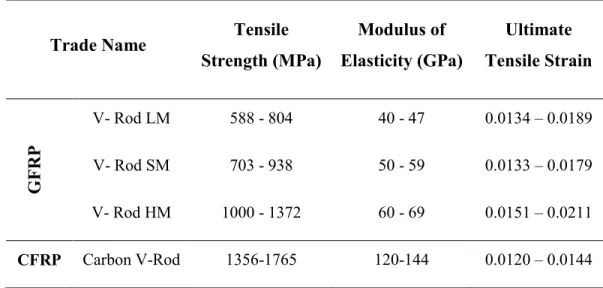
Table 2-5: Typical mechanical properties of V-ROD GFRP bars manufactured by Pultrall Inc. ... 26
Table 3-1: Steel reinforcing properties ... 60
Table 3-2: Mechanical properties of the GFRP reinforcement ... 62
Table 3-3: Mechanical properties of the CFRP reinforcement ... 63
Table 3-4: Test Matrix and Specimens Details ... 67
Table 4-1: Test matrix and details of specimens ... 85
Table 4-2: Guaranteed properties of GFRP and CFRP reinforcing bars as reported by the manufacturer ... 85
Table 4-3: Mechanical properties of the deformed steel bars ... 85
Table 4-4: Test results ... 91
Table 4-5: Available shear design equations for calculating the concrete contribution, cf
xxxii
Table 4-6: Comparison of experimental and predicted shear capacities ... 113
Table 5-1: Test matrix, specimen details, and summary of test results ... 123
Table 5-2: Mechanical properties of the GFRP and steel reinforcements ... 125
Table 5-3: Shear design provisions for calculating Vcf and Vsf ... 141 Table 5-4: Comparison between predicted and experimental shear strength ... 142
Table 6-1: Shear design provisions ... 151
Table 6-2: Mechanical properties of the GFRP bars and spirals according to the manufacturer ... 154
Table 6-3: Details of specimens and test results ... 155
Table 6-4: Predicted shear strength of test specimens ... 176
Table 7-1: Mechanical properties of the CFRP and steel reinforcement ... 194
Table 7-2: Test matrix, specimen details and summary of test results ... 195
Table 7-3: Shear design provisions for calculating Vcf and Vsf ... 214 Table 7-4: Comparison between predicted and experimental shear strength ... 215
xxxiii
NOTATIONS
f
A = total cross-sectional area of FRP longitudinal tension reinforcement, mm2
g
A = total cross-sectional area of the member, mm2
s
A = total cross-sectional area of steel longitudinal tension reinforcement mm2
a = shear span, mm g
a = nominal maximum size of coarse aggregate, mm
/
a d = shear span-to-depth ratio
w
b = web width, mm
c = neutral-axis depth for the cracked transformed section, mm
D = total diameter of circular member, mm
r
D = diameter of the circle passing through the centers of bars, mm d = effective depth of tensile reinforcement, mm
b
d = bar diameter, mm
v
d = effective shear depth, mm
f
E = modulus of elasticity of FRP reinforcing bars, MPa
s
E = modulus of elasticity of steel reinforcing bars, MPa
v
E = modulus of elasticity of FRP spirals, MPa c
E = modulus of elasticity of concrete, MPa
c
f = specified compressive strength of concrete, MPa '
cu
f = characteristic concrete cube strength, MPa
cr
f = cracking strength of concrete, MPa
mcd
f = design compressive strength of concrete allowing for size effect, MPa
ftu
xxxiv
fu bent
f = strength of bent portion of FRP bar, MPa
fv
f = stress in FRP spirals, MPa
vcd
f = 0.2 1/3 0.72 / 2
c
f N mm
k = ratio of depth of neutral axis to reinforcement ratio
1
k = shear enhancement coefficient d
M = design bending moment, N·mm f
M = design bending moment, N mm
f
M = factored bending moment, N mm
o
M = decompression moment, N mm f
N = factored axial force, N
d
N = design axial force, N f
n = ratio of modulus of elasticity of reinforcing bars to modulus of elasticity of
concrete
S = spacing of spirals, mm ze
S = effective crack spacing for members without stirrups c
V = concrete shear strength, N cf
V = FRP concrete shear strength, N exp
V = experimental shear strength, N
f
V = factored shear force, N
pred
V = predicted shear strength, N
sf
V = FRP shear reinforcement strength, N
r
V = total shear resistance of the section, N
z = distance between points of action of tensile and compressive resultant forces;
xxxv
b
= member safety factor
c
= strength safety factor for concrete
m
= materials partial safety factor
x
= longitudinal strain at mid-height of the cross section λ = factor accounting for concrete density
f = FRP-longitudinal-reinforcement ratio s = steel-longitudinal-reinforcement ratio f = FRP-longitudinal-reinforcement ratio fv = FRP-spiral-reinforcement ratio
= angle of inclination of the spiral (in degrees)
= angle of inclination of the principle diagonal compressive stress
c
= resistance factor for concrete
= factor used to account for shear resistance of cracked concrete N
1
CHAPTER 1
INTRODUCTION
1.1
Back Ground and Problem Definition
Reinforced concrete (RC) members with circular cross section are often used in civil engineering structures, for instance as laterally loaded bridge piers and piles because they are easy to build, have a pleasing appearance, and provide equal strength characteristics in all directions under wind and seismic loads. These members are conventionally reinforced with steel bars and stirrups. In North America in particular, the corrosion of steel reinforcement in concrete bridges subjected to deicing salts and/or aggressive environments constitutes the major cause of structure deterioration, leading to costly repairs and rehabilitation as well as a significant reduction in service life (Mohamed et al. 2014). Estimates indicate that the United States spends billions of dollars annually to repair and replace bridge substructures such as pier columns ($2 billion), and marine piling systems ($1 billion) (NACE International). Government agencies and industrial firms are looking for infrastructure systems that are stronger, last longer, are more resistant to corrosion, cost less to build, maintain and repair. Engineers all over the world are challenged and in search of new and affordable construction materials as well as innovative approaches and systems to problem solving.
The use of fiber-reinforced polymer (FRP) as an alternative reinforcing material in RC structures has emerged as an innovative solution to the corrosion problem in structural members subjected to severe environmental exposure (ACI 440.1R-15, Ali et al. 2015a). Fiber-reinforced polymer bars offer many advantages over conventional steel bars, including a density of one-quarter to one-fifth that of steel, greater tensile strength than steel, and no corrosion even in harsh chemical environments (Rizkalla et al. 2003; El-Salakawy et al. 2003; Benmokrane et al. 2006 and 2007). Using FRP reinforcing bars in RC members such as bridge piers and piles, the most component structural element
2
vulnerable to corrosion deteriorations because of the direct exposure to deicing salts and/or aggressive environments constitutes, can extend the lifetime serviceability, reduce maintenance costs, and improve life-cycle cost efficiency. Moreover, FRP bars may also reduce construction costs by eliminating the need for waterproofing membranes and pavement items (Benmokrane et al. 2006).
In the last decade, significant efforts have been made to apply FRP composites in the construction industry, and recently, structural applications of FRP composites started to appear in civil infrastructure systems. FRP composite materials have been used as internal and external reinforcement in the field of civil engineering constructions. It has been used as internal reinforcement for specimens, slabs and pavements (Rizkalla et al 2003; Benmokrane et al. 2006, Ali et al. 2015b; c), and also as external reinforcement for rehabilitation and strengthening different structures (Demers and Neale 1998; Teng et al. 2002).
Recent studied have produced valuable research work on and widespread applications of FRP bars to investigate the flexural and shear behaviors of RC members (ISIS Canada 2009; El-Salakawy et al. 2003; Benmokrane et al. 2006; El-Salakawy and Benmokran 2004). The shear strength of FRP RC members with rectangular cross sections has received considerable attention. The experimental work has focused mainly on members without web reinforcement, but limited research has addressed members with bent FRP stirrups (Razaqpur and Spadea 2015; Ahmed et al. 2010(a, and b); El-Sayed and Benmokrane 2008; Fico et al. 2008; Shehata et al. 2000). Nonetheless, no research seems to have investigated circular concrete members reinforced with FRP reinforcement under shear loads. Moreover, the code rules and guidelines for the shear design of circular concrete members are almost nonexistent. This leaves a research gaps in need of valuable investigations to introduce appropriate provisions in guidelines and codes for the design issues of FRP-RC circular members under shear loads.
3
1.2
Research Significance
The need for more experimental data for circular members failing in shear and the little knowledge on the shear behavior of circular members reinforced with FRP bars and spirals are the primarily motivations for this research. In particular, considerable research work has been reported, in the last decade, on the flexural and shear behaviors of rectangular RC members with FRP bars and stirrups. The level of understanding of structural behavior has reached a stage where several codes and design guidelines have been issued and developed around the world. On the other hand, no research seems to have investigated circular concrete members reinforced with FRP reinforcement under shear loading. The lack of understanding of such behavior, however, represents a significant hurdle to a broader application of FRP bars in circular members.
The scope of this study consists of experimental and analytical investigations. The experimental program is designed to provide much needed understanding of the behavior of circular FRP-RC members through design, construction, instrumentation, and testing 20 full-scale specimens. Also, the present study attempts to enrich the database of shear behavior of circular concrete members reinforced with glass-FRP (GFRP) or carbon-FRP (CFRP) bars and spirals. The effect of different parameters such as; type of reinforcement, longitudinal reinforcement ratio, shear reinforcement ratio (spiral diameter and spacing), and shear-span-to-depth ratio were investigated. On the other hand, the analytical investigation examines the validity of the available shear design provisions concerning FRP bars and spirals as well as the available analytical approach using Response 2000, which is based on the modified compression field theory. The information is valuable for designers using FRP bars and spirals in circular concrete members and for the development of codes and standards.
4
1.3
Research Objectives
In recent years, the using of FRP has been successful for different concrete structure members. To date, no experimental research concerning the shear behaviour of circular concrete members reinforced with FRP bars and spirals. The present study aims to provide basic technical information about the shear behavior of circular concrete members, reinforced longitudinally and transversally with GFRP/CFRP bars and spirals through experimental investigation and analytical study. The objectives of this study can be summarized as follows:
1. To evaluate the shear behavior and concrete contribution Vcf of circular FRP-RC
members without web reinforcement, considering the effect of reinforcement ratio and the modulus of elasticity of the reinforcing bars.
2. To investigate the shear behavior of circular RC members reinforced longitudinally and transversely with GFRP/CFRP bars and spirals, respectively, and to evaluate the contribution of the GFRP/CFRP spirals Vsf to the shear
resistance.
3. To investigate the effect of the shear-span-to-depth ratio (a/d) on the shear resistance and behavior of circular RC members reinforced with GFRP bars and spirals.
4. To examine the validity of the current shear design provisions in predicting the shear strength of circular RC members reinforced with GFRP/CFRP bars and spirals.
5. To propose new shear design equations for evaluating the concrete contribution Vcf and contribution of FRP spirals Vsf for circular RC members reinforced with
GFRP/CFRP reinforcements.
6. To create database on the shear behavior of circular concrete members reinforced with GFRP/CFRP bars and spirals.
5
1.4
Methodology
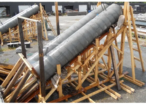
To achieve the aforementioned objectives of this research, extensive experimental and analytical programs were conducted. The experimental phase included constructing and testing of twenty full-scale circular RC specimens, 500 mm in diameter and 3,000 mm in length, reinforced with FRP bars and spirals and divided into five series as follows:
Series I: includes 2 reference specimens; one specimen reinforced with steel bars and spirals, and one specimen reinforced with steel bars and without spirals.
Series II: includes 3 specimens internally reinforced with GFRP bars and without spirals.
Series III: includes 5 specimens reinforced longitudinally with GFRP bars and spirals (GFRP Type I).
Series IV: includes 6 specimens reinforced longitudinally with GFRP bars and spirals (GFRP Type II).
Series V: includes 4 specimens; three specimens reinforced longitudinally with CFRP bars and spirals, and one specimen reinforced longitudinally with CFRP bars and spirals.
In this study, the test parameters were proposed to include the following variables: type of reinforcement, longitudinal reinforcement ratio, shear reinforcement ratio (spiral diameter and spacing), and shear-span-to-depth ratio.
The analytical investigation included analysis of the test results using the different available shear design provisions pertinent to structural members reinforced with FRP stirrups. The test results of each specimen were compared to the predicted values using different design codes and guidelines as well as recently developed shear design equations appearing in the literature. The analytical investigation extended to include the analysis of test specimens using the modified compression field theory (Response 2000).
6
1.5
Structure of the Dissertation
This dissertation consists of eight chapters, references, list of figures, and symbols. The content of these chapters is as follows:
Chapter 1: This chapter defines the problem and presents the main objectives of this
study, followed by the methodology to achieve the objectives and scope of this research study. In addition, the structure of the dissertation is presented.
Chapter 2: This chapter provides a literature review concerning the shear behavior of RC
member either with or without shear reinforcement. A full historical review which deals with the previous work on FRP mechanical properties, the main factors influencing the shear behavior of RC members under shear loads, and the currently available equations for predicting shear capacity of reinforced concrete members in the design codes and guidelines in North America.
Chapter 3: This chapter describes the experimental program, which included the
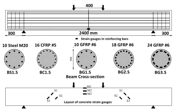
construction and testing of twenty full-scale circular concrete specimens reinforced with GFRP, CFRP, and steel bars and spirals. This chapter describes the experimental work program, specimens’ details, the used materials, specimens’ fabrications, test procedure, test setup, and measuring devices.`
Chapter 4: This chapter presents the first paper in this dissertation which submitted in
ASCE’s Journal of Engineering Structural. The paper is titled ―Strength and Behavior of Circular FRP-Reinforced Concrete Sections without Web Reinforcement in Shear‖. This paper shows the experimental test results investigation on the shear behavior of four full scale circular RC specimens reinforced with GFRP bars and without shear reinforcement, in addition to, one reference specimen reinforced with steel bars. The analysis and discussions of these results are presented. These discussions are based on modes of failure, effect of various test variables on the behavior of GFRP-RC specimens, load– deflection response, longitudinal reinforcement and concrete strains, shear-crack width
7
relationships, and shear strength of tested specimens. Moreover, the experimental results were compared to current codes and design guidelines as well as to recently developed shear design equations appearing in the literature.
Chapter 5: This chapter presents the second paper in this dissertation which submitted in
ACI Structural Journal. The paper is titled ―Shear Strength of Circular Concrete Members Reinforced with Glass-FRP Bars and Spirals‖. The paper aims to investigate the behavior performance of circular RC members reinforced with GFRP bars and spirals. The results of the tested specimens are presented in terms of flexure reinforcement and concrete strains, load-deflection response, and modes of failure. The results of the tested specimens are also presented and discussed including shear strength, load-spiral strains relationship, cracking pattern and contribution of GFRP spirals. Comparisons between the experimental test results and the theoretical predictions by three North American codes and design guidelines are performed. Also, a new equation was introduced to quantify Vsf in circular concrete members to account for the mechanical properties and
geometry of GFRP spirals. Based on the test results and the analysis, the shear capacity of GFRP-RC members with circular cross sections may be determined with the approaches developed for rectangular sections provided that certain modifications are made to take into account the effective shear depth, equivalent breadth, and the mechanical properties and geometry of GFRP spirals.
Chapter 6: This chapter presents the third paper in this dissertation which was submitted
in Journal of Composites for Construction. The paper is titled ―Shear Behavior of Circular Concrete Members Reinforced with GFRP Bars and Spirals at Shear-Span-to-Depth Ratios between 1.5 and 3.0‖. The purpose of this study is concerned with determination of the effects of shear-span-to-depth ratio( / )a d , and shear reinforcement ratio (spiral spacing and diameter) on the shear strength and behavior of circular RC members. The general behavior of the tested specimens is presented in terms of flexural reinforcement and concrete strains, load-deflection response, and modes of failure. The shear behavior of the tested specimens is also presented and discussed including
load-8
spiral strains relationship, shear cracking pattern, effectiveness of spirals, effect of shear-span-to-depth ratio, and strut and tie action. The analysis of the results includes the effect of different parameters on the shear response of circular members reinforced with GFRP bars and spirals such as, shear-span-to-depth ratio (a/d), and shear reinforcement ratio (spiral spacing and diameter). In addition, the shear strengths of the tested specimens are analyzed using the different available shear design provisions and the results of the analysis are compared with the corresponding experimental values. The analytical study was extended to include the modified compression field theory (MCFT) for predicting the shear behavior using the Response 2000 program.
Chapter 7: This chapter presents the experimental and theoretical study on the shear
behavior of circular concrete memebrs reinforced with carbon FRP bars and spirals which submitted as a journal paper in Journal of Composites for Construction, ASCE. The paper is titled ―Behavior of Circular Concrete Members Reinforced with Carbon FRP Bars and Spirals under Shear‖. The paper aims to investigate the behavior performance of circular RC members reinforced with CFRP bars and spirals. The results of the tested specimens are presented in terms of flexure reinforcement and concrete strains, load-deflection response, and modes of failure. The results of the tested specimens are also presented and discussed including shear strength, load-spiral strains relationship, cracking pattern and contribution of CFRP spirals. The experimental shear strengths of the CFRP-reinforced concrete specimens were compared to theoretical predictions provided by current codes and design guidelines. The comparison indicated that the current CAN/CSA S6-14; CAN/CSA S806-12 ACI 440.1R-15 design methods provide a reasonable predictions; however, the and JSCE 1997 underestimate the contribution of the CFRP spirals (Vsf) due
to low strain limits. A more precise formula for the shear strength Vsf, however, was
proposed to account for the contribution and behavior of CFRP spirals.
Chapter 8: This chapter includes a summary of this investigation and the overall
conclusions based on the experimental and analytical results conducted in this dissertation. As well as, recommendations for further research work are also given.
9
CHAPTER 2
LITERATURE REVIEW
2.1
General
The long-term durability of reinforced concrete (RC) structures has become a major concern in the civil-engineering construction industry. One of the main factors reducing durability and service life of reinforced-concrete structures is the corrosion of steel reinforcement. Recently, the use of fiber-reinforced polymer (FRP) as alternative reinforcing material in RC structures has emerged as an innovative solution to overcoming the corrosion problem. Today, public agencies and regulatory authorities in North America have included FRP bars and stirrups as a premium corrosion-resistant reinforcing material to reinforce concrete structures subjected to flexural and shear loads. In the last decade, extensive research on the flexural behavior of FRP-RC members has been extensively investigated and incorporated in the most of the current design codes with well-defined simple design equations. On the other hand, the dilemma of shear behavior of reinforced and prestressed concrete members has not yet been settled in spite of the extensive research work conducted in this area. This is related the complexity of this phenomenon, which involves many variables that cannot be rationalized into a simple model. Several models are introduced by different codes and design defining the design procedure and the applicability conditions.
2.2
Shear Transfer Mechanisms of Concrete Members
The fundamental mechanisms by which flexural elements transfer shear are illustrated in the simple free-body diagram in Figure 2-1. Joint ACI-ASCE Committee 445 (1998) reported that, after the formation of the diagonal cracks in members without shear reinforcement, the shear is carried by concrete as a combination of five mechanisms of shear transfer: 1) shear stresses in uncracked concrete; 2) interlocking action of