Any correspondence concerning this service should be sent to the repository administrator:
[email protected]
O
pen
A
rchive
T
oulouse
A
rchive
O
uverte (
OATAO
)
OATAO is an open access repository that collects the work of
Toulouse researchers
and makes it freely available over the web where possible.
This is an author -deposited version published in:
http://oatao.univ-toulouse.fr/
Eprints ID: 4919
To link to this article: DOI:
10.1007/s10626-011-0103-1
URL:
http://dx.doi.org/10.1007/s10626-011-0103-1
To cite this version: FERRANDIZ Thomas, FRANCES Fabrice, FRABOUL Christian.
Worst-case end-to-end delays evaluation for SpaceWire networks. Discrete Event Dynamic
Systems, 2011, vol. 21, n° 3, pp. 339-357.
(will be inserted by the editor)
Worst-case end-to-end delays evaluation for SpaceWire
networks
Thomas Ferrandiz · Fabrice Frances · Christian Fraboul
Received: date / Accepted: date
Abstract SpaceWire is a standard for on-board satellite networks chosen by the ESA as the basis for multiplexing payload and control traffic on future data-handling architectures. However, network designers need tools to ensure that the network is able to deliver critical messages on time. Current research fails to address this needs for SpaceWire networks. On one hand, many papers only seek to determine probabilistic results for end-to-end delays on Wormhole networks like SpaceWire. This does not provide sufficient guarantee for critical traffic. On the other hand, a few papers give methods to determine maximum latencies on wormhole networks that, unlike SpaceWire, have dedicated real-time mechanisms built-in. Thus, in this paper, we propose an appropriate method to compute an upper-bound on the worst-case end-to-end delay of a packet in a SpaceWire network.
Keywords embedded network · wormhole routing · worst-case end-to-end delays · performance evaluation · SpaceWire
This work was funded by a PhD grant from the CNES and Thal`es Alenia Space. T. Ferrandiz
Universit´e de Toulouse, ISAE 10 avenue Edouard Belin
BP 54032, F-31055 Toulouse Cedex 4 Tel.: +33 5 61 33 90 93
E-mail: [email protected] F. Frances
Universit´e de Toulouse, ISAE [email protected] C. Fraboul
Universit´e de Toulouse, INPT-ENSEEIHT-IRIT 2, rue Charles Camichel
BP 7122, 31071 Toulouse Cedex 7 [email protected]
1 Introduction
SpaceWire [Parkes and Armbruster (2005),ECSS (2008)] is a high-speed on-board satellite network created by the European Space Agency and the University of Dundee. It is designed to interconnect satellite equipment such as sensors, memories and processing units with standard interfaces to encourage re-use of components across several missions.
SpaceWire uses serial, bi-directional, full-duplex links, with speeds ranging from 2 Mbps to 200 Mbps, and simple switches to interconnect nodes with arbitrary topologies.
In the future, SpaceWire is scheduled to be used as the sole on-board network in satel-lites. As a high-speed network with low power consumption, it is well-suited to this task. It will be used to carry both payload and control traffic, multiplexed on the same links. These two types of traffic have different requirements. Control traffic generally has a low through-put but very strict time constraints. On the contrary, payload traffic does not need strict guarantees on the end-to-end delays of packets but requires the availability of a sustained, high bandwidth to be operational.
Both requirements were easy to satisfy on point-to-point SpaceWire links. But in order to connect every terminal on a single SpaceWire network, a switch was designed with space constraints in mind (especially radiation constraints on memory) which led to the use of Wormhole Routing.
However, the problem with using Wormhole Routing is that it can occasionally lead to long delays if packets are blocked as shown in our SpaceWire overview in Section 2. Those blocking delays make it difficult to predict end-to-end delays especially when control and payload traffic are being transmitted on the same network.
Previous delay evaluation methods on Wormhole networks (see Section 3) have either focused on probabilistic results which do not provide enough guarantee or have studied Wormhole networks with built-in mechanism that make deterministic communications pos-sible. Since SpaceWire does not integrate such mechanisms, we have designed a new method to compute an upper-bound on the worst-case end-to-end transmission delay of a packet across a SpaceWire network. This provides a reasonably simple and elegant way to guaran-tee the strict respect of temporal constraints. Section 4 presents this method and the results of a case-study are given in Section 5. Finally, we conclude and propose future topics for research in Section 6.
2 A brief description of SpaceWire
Originally, SpaceWire was designed to provide only point-to-point links between satellite equipment. It is derived from the IEEE 1355 standard [IEEE Computer Society (1996)] but uses new connectors and cables suitable for space usage.
On each link, a flow control mechanism ensures that the emitter can only send data when the receiver has enough buffer space to store it. In fact, the emitter can only send data if the receiver sent it a Flow Control Token (FCT). Each FCT allows the emitter to transmit 8 characters. At most, 56 characters can be allowed at any moment on a given link.
Data is organized in packets of arbitrary length with a very simple format. It is even possible to send packets of unlimited size. Of course, higher level protocols will use more complex packet formats.
SpaceWire’s point-to-point links thus provide a simple and fast way to transmit data be-tween two terminals. Furthermore, the end-to-end delay is simple to compute. If the source
and destination do not cause delays themselves, the delay is T
C where T is the packet size and C the capacity of the link.
With the increasing quantities of data exchanged by various equipment, using only point-to-point links to connect all the equipment would be too costly. Furthermore, in order to reduce the complexity of the on-board system, it would be better to use a single network to carry both payload and command/control traffic instead of using a dedicated bus (generally a MIL-STD-1553B bus) for the control traffic and high-speed SpaceWire links for the payload traffic.
These considerations have led to the addition of switches to the SpaceWire standard, allowing designers to build networks with arbitrary topologies. These switches are required to comply with two main constraints. Firstly, they must remain compatible with the point-to-point links used to interconnect equipment and secondly, memory consumption must be strictly restricted because radiation tolerant memory is very expensive.
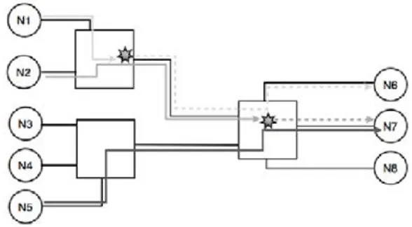
Fig. 1 Wormhole routing and the blocking problem
As a consequence, Wormhole Routing was chosen as the way to transmit packets through the network. With this technique, instead of buffering whole packets, a switch uses the first character as soon as it is received to determine the appropriate output port (see Figure 1) using a static routing table. If the output port is free, the packet is transferred on-the-fly: the switch transmits the characters as they arrive and does not need to store a complete packet. There is no queue in the output port. When the output port is allocated to the packet, it is marked as occupied by the switch and no other packet can pass through as long as the current packet has not been completely transferred.
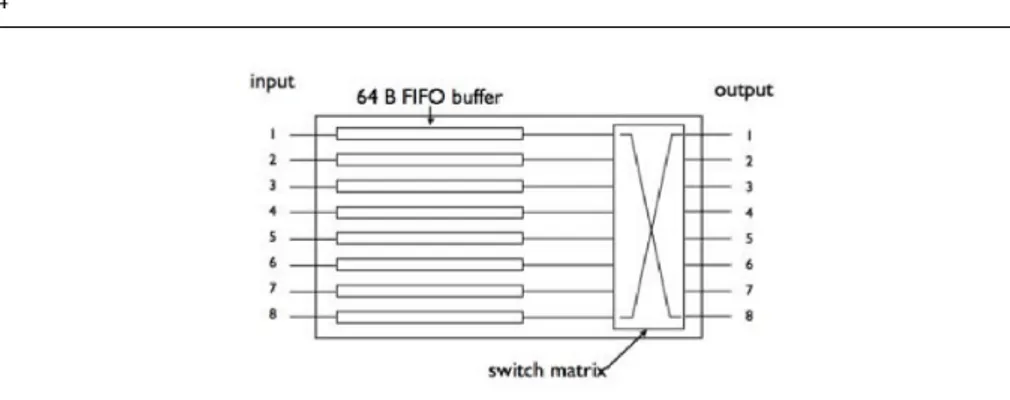
This means that, if the output port is already occupied by a packet, a second packet will have to wait until the first one has been transferred. Given that the flow control mechanism is active on each link, the first characters of the second packet will continue to arrive into the input port and will be stored in a small 64-byte buffer (see Figure 2 ) in the hope that the output port becomes available again. The flow control mechanism will then prevent the upstream switch or terminal from sending additional characters. In turn, this packet will block access to all the output ports it went through in the upstream switches.
When two or more flows are waiting for the same output port to become free, a simplified Round-Robin mechanism is used to determine which one will get access to the packet. The mechanism guarantees that each input port gets a fair access to the output port but does not enforce a bounded access duration for each flow.
Fig. 2 A 8x8 SpaceWire switch
An additional mechanism was added to help reduce the blocking delay for urgent pack-ets. It is a two-level static priority scheme that is used in switches so that packets sent to a high-level address are always transmitted before packets sent to low-level addresses. As SpaceWire switches are not preemptive, the priority mechanism is only applied when two packets are waiting for the same output port to be freed. The Round-Robin scheme is then used to arbitrate between packets of the same priority level.
As can be seen, using Wormhole Routing satisfies both constraints cited above. Switches need little memory for each input port and no memory at all for output ports. They are also backward compatible since they propagate the point-to-point SpaceWire flow control to each link along the end-to-end path, backwards from the receiver to the emitter.
However, blocking can become a major problem when using a Wormhole network for real-time communications. Even the priority mechanism is not enough to guarantee small network latency because it is not preemptive. Thus, we need a way to compute the end-to-end delay of each flow in the network.
3 The end-to-end delay determination problem: related work
Optimally, a packet is not blocked in any encountered switch and endures only the switching delay of each switch. The switching delay includes the time to read the header of the packet, determine the output port and copy the first character to the output link. SpaceWire switch specifications require the switch’s switching delay to be less than 0.5 µs when links work at 200 Mbps. This means that the delivery time of a packet across a SpaceWire network will be equal to the delivery time on a point-to-point link plus 0.5 µs per switch crossed.
However, access conflicts can occur on each link taken by a packet. Furthermore, the packet blocking a link can in turn be blocked farther on the network. This makes it very hard to determine the end-to-end delay of a single packet analytically.
A great deal of research has been published on the estimation of end-to-end delays in Wormhole Routing networks, particularly in supercomputers. However, that research mostly seeks to determine average latency using techniques like queuing theory (see [Draper and Ghosh (1994)] and [Dally (1990)] for example). Knowledge of average latency is not suf-ficient here since we must be certain that all messages are delivered within an acceptable timeframe.
Other papers explain how to use wormhole networks for real-time communications in supercomputers. However, the wormhole networks they consider all make use of virtual channels [Dally (1992)]. This mechanism allows a point-to-point link to be shared by several
packets simultaneously thanks to multiple input buffers in the receiver. It is thus possible to use preemptive static priority schemes to prioritize urgent traffics on the network and make sure that deadline are met. [Mutka (1994)] describes the use of the Rate Monotonic Scheduling algorithm to design a wormhole network satisfying real-time constraints. [Kim et al (1998)] also describes a priority allocation scheme and the algorithms to compute an upper-bound on the worst case communication delays. However, virtual channels consume a lot of memory since every channel must have a dedicated buffer in each switch used. Since SpaceWire was designed to use as little memory as possible, it was not possible to include them. Furthermore, without virtual channels it is not practical to implement preemptive priority because this would mean canceling the preempted packets. As a consequence, we cannot use those algorithms to study a SpaceWire network.
A modification of the wormhole routing scheme is required to allow the use of preemp-tion with few virtual channels (even only one). Balakrishnan and ¨Ozg¨uner (1998) proposed a new routing scheme they called Preemptive Pipeline Circuit Switching for Real-Time mes-sages (PPCS-RT). This scheme requires a global static ordering of the mesmes-sages from the highest priority message to the lowest priority one. The transmission of a packet is then split into two phases. During the first one, only the header is transmitted and reserves the port in each switch. When the header reaches the destination, a signal is sent to the source of the packet and the body of the packet is transmitted along the reserved path. The difference with basic wormhole routing is that, during the first phase, reserved ports can be preempted by higher priority packets. The preempted packet must then be retransmitted. This mechanism allows the use of preemption without additionnal memory but requires some modifications in the switches and is thus unsuitable for SpaceWire. Furthermore, the authors give a model, called the lumped link model, to compute the worst-case end-to-end latency of a packet. However, the equation they give applies only to their routing scheme with preemption, not to usual wormhole routing network.
Lu et al (2005) proposed an enhancement of the lumped link model called the contention tree model. This model introduces a difference between direct and indirect interferences which allows to compute tighter upper-bound. However, it still requires a complete ordering of the messages and is thus inappropriate for our study.
Recently, wormhole networks have regained attention for use on Network-On-Chips (NoC). Those networks’ designers share SpaceWire’s concerns for low memory usage. As such, there’s been some research seeking to guarantee timely delivery while maintaining memory consumption low. This means using fewer priority levels and virtual channels.
In Shi and Burns (2009), the authors present a priority scheme they call Priority Share Policy. Its basic principle is that, instead of being dedicated to one data flow as in classic priority scheme, each virtual channels is shared by a number of flows with the same priority level. This model, used with a unique virtual channel for every flow, matches the behavior of a SpaceWire network when switch-level priorities are not used. The authors then describe how to compute an upper-bound on the maximum network latency for a set of flows of identical priority. The idea behind the computation of the maximum network latency is to consider all the flows of the same priority as one composite flow using all the network resources of the flows in that priority level. The maximum network latency of a given flow is then the maximum network latency of the aggregate flow plus the release jitter of the flow itself. This method will work well if it used with short packets that all have relatively low latencies. However, in our case, we would have to use it with only one composite flow for both short, low-latency packets and long, high-latency packets. This would lead to very high and unrealistic latencies for short packets. Thus, since we only use one priority level, we need a method that allows us to compute more precise delay for each flow.
Network Calculus [Le Boudec and Thiran (2004)] is another technique that has been successfully used to evaluate bounds on worst-case end-to-end delays in embedded net-works. For example, it was used in [Mifdaoui et al (2007)] to analyze a Switched Ethernet network used to replace a MIL-STD-1553B bus in a military avionic network. However, we could not model Wormhole switches using service curves because the service offered to a flow depends on the other flows in the network and on the network topology.
In [Qian et al (2009)], the authors present a way to model a Wormhole network using the Network Calculus theory. But, in order to determine the service curve of a switch, they need to assume that the delay spent by a packet in the switch is bounded. They choose to do so by using a weighted round-robin policy to manage access to the output ports. It is then possible to compute an equivalent service curve for each switch. Once all the equivalent service curves have been determined, an upper-bound on the end-to-end delay can be computed. However, to determine the duration of each round-robin slot, we need to know how long a packet can block the output port. Since this would be equivalent to knowing its worst-case end-to-end delay, we are stuck with a circular dependency problem if we try to use the method proposed in this paper.
Overall, previous work about real-time communications on Wormhole networks divides into two categories. The first revolves around supercomputers and studies wormhole net-works without memory constraints and specifically designed to be used as real-time com-munication networks through the use of virtual channels. The second one is concerned about Networks-on-Chip. Although those networks are as memory constrained as SpaceWire, they seem to be mostly designed essentially to carry short packets with small latencies. These work do not apply to SpaceWire for two reasons. First, unfortunately, SpaceWire was de-signed to have low memory consumption but was not optimized for real-time communica-tions. As such, it has no equivalent of the virtual channels. Secondly, we want to be able to take into account packets of very large size together with short packets. Thus our problem does not completely match the hypothesis of papers studying real-time communications on Networks-On-Chip.
We should also mention that, although SpaceWire lacks mechanisms specifically de-signed to handle real-time communications, an extension called SpaceWire-T (for Timeli-ness) is currently being developed by the University of Dundee and the ESA to address this limitation [Parkes (2009)]. It works as a Quality-Of-Service layer between applications and the SpaceWire network. Since it does not modify the base standard, it cannot make use of character-level preemptive priority like other networks. SpaceWire-T offers two different modes. In asynchronous mode, it uses packet segmentation, source-level priorities and an end-to-end flow-control mechanism to help offset the blocking problem. This mode does not guarantee the strict respect of deadlines. In synchronous mode, SpaceWire-T uses a Time Division Multiple Access mechanism to manage access the network and guarantee a strict respect of deadline. SpaceWire-T should help make SpaceWire better suited to real-time communications. The problem is that it is not yet a standard and compatible equipment will not be available for several years. Additionally, using it will likely require modifications to the existing applications which will delay its deployment even more. Thus, at the moment, satellite manufacturers have to use pure SpaceWire network for real-time communications.
Therefore, we propose a way to compute an upper-bound on the worst-case end-to-end delay of a flow traversing a SpaceWire network, which takes into account long packets as well as shorter packets and does not require the use of virtual channels or other additional mechanisms.
4 Computing a bound on the worst-case delay
4.1 Overview of the computation
The method of computation is based on the idea that, as far as delays are concerned, the delivery of a packet p is equivalent to the following two-phase delivery. During the first phase, the first character (the header) of p is routed to its destination through intermediary switches and creates a ”virtual circuit” between the source and destination of the packet using Wormhole Routing. During this phase, the header may be delayed in two ways. Firstly, if other flows have the same source as p, the header may have to wait before they have been completely transferred to access the source’s output link. Secondly, in each switch, packets from other flows may be competing with p to use the same output links as p. These packets may also get blocked farther in the network. Because of the flow control, p will be blocked in the switch as long as the blocking packets have not been completely transferred. When the header finally accesses the output link, it is transferred to the next switch where it may also get blocked by competing flows. This property allows us to derive a recursive definition of the worst-case end-to-end delay for p.
In the second phase, the whole packet can be transferred along the path of the circuit, as if it was a point-to-point link. When the packet’s transfer is completed, the links are freed and the ”virtual circuit” disappears. The packet does not suffer any delay during this phase and its duration is simply the time needed to transfer p on a point-to-point link the speed of which is the minimum speed of all the links used by the virtual circuit. This gives us the basic case for the recursion.
Please note that this two-phase delivery is only a model. In practice, the packet is a single piece of data (although possibly very large) that progresses through the network and prevents other packets from using the same links during its progression. We are thus slightly overestimating the end-to-end delay of the packet.
4.2 Notations and definitions
We model a SpaceWire network as a connected directed graphG (N,L). The nodes N of the graph represent both the terminals and the SpaceWire switches. The edges L represent the set of SpaceWire links. We use two edges in opposite directions to represent a bi-directional link. Since there may be multiple links between two switches,G (N,L) may be a multigraph. The case of multiple links between two given nodes is only considered when both nodes are switches. If a terminal has several SpaceWire interfaces, we model it as several terminals with only one interface.
A communication between a source and a destination is modeled as a flow f . Each flow f has a maximum packet size, noted Tf. This includes the protocol headers. Each flow goes through a set of links that form a path inG (N,L). The set of flows is denoted F. Knowing the throughput of every flow is not necessary but we make the assumption that when the time goes to infinity, the size of each source emission buffer is bounded. Otherwise, the worst-case end-to-end delay would not be finite.
We note links( f ) the ordered list of the links the flow f follows. f irst( f ) returns the first link in links( f ). We note next( f , l) the function which, given a flow f and a link l in links( f ) returns the next link in links( f ) right after l and prev( f , l) the function that returns the previous link in links( f ) just before l. If l is the last link in links( f ), next( f , l) returns null. If l is the first link in links( f ), prev( f , l) returns null.
We also make the following assumptions:
– the routing is static (current SpaceWire switches use static routing anyway) ; – all the links of a group have the same capacity ;
– we do not take into accounts addresses priorities in the switches (i.e. all nodes have low priority addresses) ;
– only one packet of a flow may be present at any given time in the network ;
– for any given flow f , Tf ≥ size(links( f )) × (input bu f f er size). Otherwise, a packet could be stored entirely in the intermediary switches and the two-phase delivery hy-pothesis would not hold ;
– we neglect the delays caused by Time-Codes and Flow Control Tokens (Time-Codes are special characters used by SpaceWire to synchronize a global clock on the network) ; – when a source starts to send a packet, it transmits the packet at the maximum possible
speed until the entire packet has been transferred (i.e. the source itself does not delay the packet) ;
– the destination may postpone the processing of an incoming packet during a constant delay Ddest, identical for each packet addressed to this node.
4.3 The method of computation
Let us consider a bound on the worst case delay for packet p of flow fp. The simplest case is when l is null. It means that the first character of the packet has arrived at its destination. Thus there is no delay due to a switch. The only remaining delay possible is the time needed to transmit the packet on the virtual circuit created and the eventual delay before the des-tination processes the packet. When all the links in links( f ) have the same capacity C, the delay is simply d( f , null) =Tf
C. However, we want to take into account the case where each link l in links( f ) may have a different capacity Cl. In this case, thanks to the flow control on each link, the overall capacity of the ”virtual circuit” will be the minimum capacity of the links used by f . Thus the delay for l = null is
d( f , null) = Tf Cf
+ Ddest with Cf= min
l∈links( f )Cl (1) On the contrary, when l = f irst( f ), it means that the emitter node of l is the source of the flow f . Since it is a terminal, no flows enter the node. However, the terminal may be source of other flows which will compete with f for access to the output link. The maximum delay that one of this packet, denoted q, may cause to p is the time needed to transmit q from the moment the node starts to transmit q. If l = f irst( f ), the delay is thus
d( f , f irst( f )) =
∑
fin∈SFd( fin, next( fin, l)) + d( f , next( f , l)) (2)
where
SF= { fin∈ F| fin6= f and f irst( fin) = f irst( f )} (i.e. SFis the set of flows that have the same source as f ).
When l 6= null and l 6= f irst( f ), p may be delayed in the switch before being allowed to access the link. In each switch, this delay has two possible causes. The first is the switching delay of the switch and includes the time needed to determine the port through which p will be transferred. This delay is constant for every packet and every switch. We will note it dsw afterwards.
The second delay occurs when the output link is already in use by another packet. Let us suppose that this link is not part of a group. With Wormhole Routing, p has to wait until the packet using the port is completely transferred. It is also possible that one or more packets coming from other ports may already be waiting for the same output port to become free. The delays will then accumulate if those packets are transferred before p. Note that, since SpaceWire switches use a crossbar switch where ports are independent of each other, only packets using the same output port as p can cause a delay.
The rotating priority scheme used by SpaceWire switches ensures that at most one packet from each of the other input link may be transmitted before p can be transferred. For each of these input links, several flows can enter the switch. Thus we need to compute a bound on the maximum delay that each of these flows may produce and then calculate the maximum of these potential delays.
The maximum delay that a packet q can cause p is the time to transfer q starting from the current switch if q was alone in this switch (i.e. q does not have to wait for the output port to become free). However, q may in turn become blocked in the next switches it crosses by other packets.
Once it can access the appropriate output link, the header of a packet is transferred to the next switch and must once again wait to access the output port it needs.
As a consequence, we can now formulate a recursive definition of an upper bound on the delay d( f , l) needed to deliver a packet of flow f starting from the moment when the packet tries to access link l with l 6= null and l 6= f irst( f ) :
d( f , l) =
∑
lin∈Bf,l[ max fin∈Ulin
d( fin, next( fin, l)) + dsw]
+ d( f , next( f , l)) + dsw
(3)
where
Bf,l= {lin∈ L, lin6= prev(l), f or which ∃ fin∈ F|next( fin, lin) = l}
(i.e. Bf,lis the set of links that are used immediately before next( f , l) by at least one flow finand that are not prev(l)) and
Ulin= { fin∈ F|lin∈ links( fin)}
(i.e. Ulinis the set of flows that use the link lin).
Thus (3) means that for every input link which a flow uses before l, we first compute the delay that the flows coming from this link may need to be transferred from this link to their destination if each of them was alone in the switch. We then take the maximum for each input link and add those values to the delay for p itself.
4.4 Taking Group Adaptative Routing into account
Group Adaptative Routing (GAR) is a mechanism added to SpaceWire in order to increase the available bandwidth. It works by putting several links in parallel between two switches and declaring them as a group in the routing table. The switches are then able to automat-ically spread the load on all the available links. This method should reduce the end-to-end delays of urgent flows which is why we are interested in it here.
Suppose now that Group Adaptative Routing is used and that link l is part of a group of at least two links. We note nlthe number in the group where l belongs, including l. Packets
coming from ports in Bf,lare not sent in sequence on l but in parallel on all the links of the group. Thus as soon as a link in the group is free, the switch sends another packet selected among those waiting to access the link. In the worst case, p is transmitted as soon as no packet is awaiting anymore and as soon as a link of the group is free. The delay is thus the busy time of the least used link in the nllinks of the group. This allows us to compute the delay for a given distribution of the packets on the nllinks of the group.
Let us denote (Bk
f,l)k∈ {1,...nl}a partition of Bf,lin nlparts. If prev( f , l) is also part of a
group, Bf,lcontains all the links of the group except prev( f , l). The delay caused by all the packets using l to p is then
D((Bkf,l)) = min k∈{1,...nl}l
∑
in∈Bkf,l
[ max fin∈Ulin
d( fin, next( fin, l)) + dsw] (4)
We then compute (4) for each possible partitioning of Bf,lin nlparts. Partitioning com-prising empty parts are included. In the end, d( f , l) is defined by
d( f , l) = Tf Cf if l = null ∑ fin∈SF
d( fin, next( fin, l)) + d( f , next( f , l))ifl= f irst( f )
max ((Bk f,l)k) D((Bk f,l)) + d( f , next( f , l)) + dsw otherwise (5)
By trying all partitioning of Bf,l, we’re forced to take into account a number of situations that cannot really happen. Given that those situations lead to better results than those really possible, it is not a problem. Since we take the maximum of the generated delays, they disappear naturally.
Note also that the third case of 5 is also correct for nl= 1 and compatible with our first formula. If nl= 1, there is only one partition of Bf,land the third case reduces to
d( f , l) =
∑
lin∈Bf,l[ max fin∈Flin
[d( fin, next( fin, l))] + dsw] + d( f , next( f , l)) + dsw
The proof of termination of the method and its complexity are given in the Appendix. The method can then be used as a tool to make trade-offs on the worst-case delays for the various flows by changing the size of packets and the topology of the network as we will show in the next Section.
5 Case study
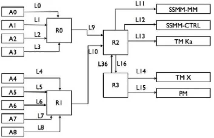
We will now present some results of the computation method on a case study. This study is based on a network architecture provided by Thal`es Alenia Space (see Figure 3) and designed for use in an observation satellite. Our goal is to determine worst-case end-to-end delay for each flow in the network.
5.1 Description of the network
As can be seen on Figure 3, the network is composed of two parts. The platform equipment on the right which includes a mass memory unit (SSMM-MM and SSMM-CTRL), a pro-cessor module (PM) and two Transmission Modules (TM Ka and TM X). The propro-cessor module monitors the other nodes and sends back commands. The mass memory is slit in two parts. Data are stored in the MM module but must go through the controller unit first. Thus, other nodes send packets to the CTRL unit. The units then applies a treatment during a constant delay and sends the packet to the MM unit. The CTRL unit only stores one packet at any given time. On the left, the application terminals (A0 to A8) represent the payload instruments. That includes cameras, radars or any kind of sensors. They send data packet to the CTRL unit and monitoring traffic to the PM unit.
Each pair of nodes is connected by two links, one in each direction. However, to keep the figure readable, we show only one link per pair. For each link i shown, the opposite link has number 20 + i. For example, we show l36which connects R3to R2since l16connects R2 to R3. All the links have the same capacity C = 50 Mbps.
Fig. 3 Network used for the case study
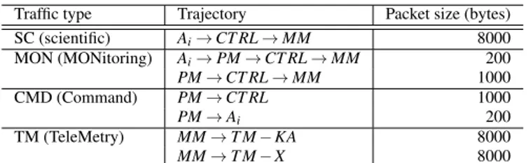
We can split the network traffic into four categories (see Table). The table gives the network path and the packet size for each type of traffic. Among all the nodes, only the CTRL and PM units introduce a delay for every packet they receive. They delay is the same for both: DPM= DCT RL= 10µs.
Some traffic further divides into several flows according to the definition we used in Section 4. In that case, we simply sum the delays for each included flow. The numbers of the different flows are given in Table 2.
Traffic type Trajectory Packet size (bytes) SC (scientific) Ai→ CT RL → MM 8000 MON (MONitoring) Ai→ PM → CT RL → MM 200 PM→ CT RL → MM 1000 CMD (Command) PM→ CT RL 1000 PM→ Ai 200 TM (TeleMetry) MM→ T M − KA 8000 MM→ T M − X 8000 Table 1 Network traffic
Flow number Type Source and Destination 0 to 8 SC Ai→ CT RL 9 SC CT RL→ MM 10 to 18 MON Ai→ PM 19 MON PM→ CT RL (retransmission) 20 MON CT RL→ MM 21 MON PM→ CT RL (generated by PM) 22 MON CT RL→ MM (generated by PM) 23 CMD PM→ CT RL 24 to 32 CMD PM→ Ai 33 TM MM→ T M − Ka 34 TM MM→ T M − X Table 2 Names of the different flows
5.2 Formal results
As an example, we will compute d( f7) by hand. We first have
d( f7) = d( f7, l7) = d( f17, l10) + d( f7, l10) (6) then d( f17, l10) =
∑
j∈{4,5,6,8} max[d( fj, l12), d( f10+ j, l12)] + d( f17, l16) + 5.dsw (7) and d( f17, l16) = max k∈{0,...,3}d( f10+k, l15) + d( f34, l14) + d( f17, l15) + 3.dsw (8) We also have d( f10+k, l15) = d( f10+k, null) + dsw∀k ∈ {0, . . . , 8} (9) and d( fj, l12) = maxk∈{0,...,3}d( fk, null)+max(d( f21, null), d( f23, null))+d( fj, null)+3.dsw∀ j ∈ {0, . . . , 8} (10) As
d( f7, l10) =
∑
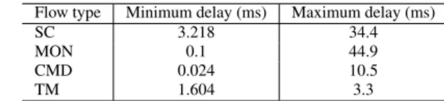
j∈{4,5,6,8}Flow type Minimum delay (ms) Maximum delay (ms) SC 3.218 34.4 MON 0.1 44.9 CMD 0.024 10.5 TM 1.604 3.3 Table 3 Maximum and minimum delay for sample flows across the network
(6) becomes
d( f7) =2.
∑
j∈{4,5,6,8}max[ max
k∈{0,...,3}d( fk, null) + max(d( f21, null), d( f23, null)) + d( fj, null) + 2.dsw, max
k∈{0,...,3}d( f10+k, null) + d( f34, null) + d( f10+ j, null)] + max
k∈{0,...,3}d( fk, null) + max(d( f21, null), d( f23, null)) + d( f7, null) + max
k∈{0,...,3}d( f10+k, null) + d( f34, null) + d( f17, null) + 24.dsw
(12)
Since we have
d( fk, null) = Tk
C + DDEST ∀k ∈ {0, . . . , 34}
with DPM= DCT RL= 10µs and all the others delay equal to 0, we finally have
d( f7) =1
C.{2.j∈{4,5,6,8}
∑
max[ maxk∈{0,...,3}Tk+ max(T21, T23) + Tj+ 3.DCT RL+ 2.dsw, max k∈{0,...,3}T10+K+ T34+ T10+ j+ 2.DPM] + max k∈{0,...,3}Tk+ max(T21, T23) + T7+ 3.DCT RL + max k∈{0,...,3}T10+K+ T34+ T17+ 2.DPM} + 24.dsw (13)The structure of the formula shows how fast delays can add up when a link is shared by many flows. Likewise, switching delays add up very fast because each packet that is trans-mitted before one from f (7) must be switched by the switch. This highlights the importance of a fast switching network to keep network latency low.
5.3 Numerical results
We wrote a simple OCaml program to implement the computation. Even a naive implemen-tation with exponential complexity is very fast on a typical satellite network like this one. We did not use Group Adaptative Routing on this network because the real bottleneck here is the CTRL unit which receives the SC packets one by one. Using Group Adaptative Routing on links l9and l10would not significantly reduce network latency because only link l12risks being overloaded and Group Adaptative Routing can only be used between two switches.
Results are given in Table 3 for a sample of flows along with the minimum delay for each flow. For a flow f , the minimum delay isTf
crossed. As shown in Table 1, SC and MON delays include two flows each. Here we took the SC and MON flows originating in A7 as an example. So SC corresponds to the path (l7, l10, l12, l32, l11) and MON to the path (l7, l10, l16, l15, l35, l36, l11).
The computed worst-case delays are very high for a 50 Mbps network but are not pes-simistic. In fact, as shown by Equation 13, the worst-case delay is reachable by construction. This highlights the important variations of the end-to-end delay that can happen in a worm-hole network. Indeed, the ratio between worst- and best-case delays is as much 449 for the MON flow. The large delay for MON flows is mostly explained by the fact that links l0 to l10are shared between MON and SC flows which then all block on link l12.
Note that even for large packets, the variability can be high. The ratio between worst-and best-case delays for SC flows is more than 10. This is because according to Equation 13, in the worst case, as much as 16 other SC packets will be transmitted before a packet from f7can be sent to the CTRL unit. On the other hand, TM flows have a ratio of only 2 because their sole conflict is with short MON packets on l16.
The high ratio (437) for CMD packets is more surprising because at first glance, CMD packets from the PM to the Ai nodes do not have any conflicts. However, in addition to the CMD packets, the PM sends MON packets to the CTRL unit and also forwards MON packets sent by the Ainodes to the CTRL unit. Since all those PM packets are in competition with SC packets for l12and we suppose that all the flows try to emit simultaneously, the final result becomes very high.
It must be emphasized that this situation, although it is very improbable, can actually arise if packets can be sent at any moment. However, our model is very generic and does not take into account the actual data rate of flows or their periodicity. In reality, it is possible that several flows with the same source but different periods or emission cycles will never try to emit at the same time. Also, when taking periods into account, a flow which appears several times in the delay of another could appear less often if its period was large.
Therefore, we plan to extend our method of computation by using a more precise traffic model. This would lead to tighter bounds but would make the model less general. Addi-tionally, it would allow us to remove the assumption that only one packet of a given flow may be present in the network at any time by integrating in the model the delays that could eventually be caused by packets of the same flow blocked in the network.
6 Conclusion and future works
We have presented a simple method of computation that allows us to compute an upper bound on the worst-case end-to-end delay of flows carried by a SpaceWire network. This bound is such that it can never be exceeded by a packet as long as the network does not fail. This is especially important for control traffic for which timely delivery is critical. The method uses a recursive definition of the delay encountered by each packet in each switch to obtain the bound and does not require assumptions on the periodicity of the traffic.
We then illustrated the use of this method on a case study based on the network architec-ture of an observation satellite. This example highlighted the huge difference between the minimal and worst-case delays for a given flow. Analyzing the results showed that shared links are the main causes of delays and can lead to large delays even for flows whose desti-nation is not overloaded.
We have three perspectives to extend our method of computation. The first one is to complete the modeling of SpaceWire by introducing packet priorities in the model. Although
it is not as useful as character-level preemptive priorities, this mechanism would contribute to lower delays for urgent flows.
At the moment, we do not make assumptions on the periodicity of the input traffic. We only suppose that each flow has a maximum packet size. Although this increases the generality of the method, it also means that the results we get may be pessimistic. Thus the second perspective is to use a more precise modeling of the input traffic to obtain tighter bounds. For example, we could use arrival curves to describe the traffic instead of assuming that each flow tries to emit at the maximum speed.
Finally, the third perspective is to model the SpaceWire-T extension once it is finalized. As explained in Section 3, this extension is designed specifically to handle real-time com-munications on a SpaceWire network. Thus, we are interested in evaluating the worst-case delay improvements that it will bring.
References
Balakrishnan S, ¨Ozg¨uner F (1998) A priority-driven flow control mechanism for real-time traffic in multiprocessor networks. Parallel and Distributed Systems, IEEE Transactions on 9(7):664 – 678, DOI 10.1109/71.707545
Le Boudec JY, Thiran P (2004) Network calculus a theory of deterministic queuing systems for the internet. Springer Verlag (LNCS 2050):1–265
Dally W (1990) Performance analysis of k-ary n-cube interconnection networks. Computers, IEEE Transactions on 39(6):775 – 785, DOI 10.1109/12.53599
Dally W (1992) Virtual-channel flow control. Parallel and Distributed Systems, IEEE Trans-actions on 3(2):194 – 205, DOI 10.1109/71.127260
Dally W, Seitz C (1987) Deadlock-free message routing in multiprocessor intercon-nection networks. Computers, IEEE Transactions on C-36(5):547 – 553, DOI 10.1109/TC.1987.1676939
Draper JT, Ghosh J (1994) A comprehensive analytical model for wormhole routing in mul-ticomputer systems. Journal of Parallel and Distributed Computing pp 1–34
ECSS (2008) Spacewire – links, nodes, routers and networks pp 1–129
Kim B, Kim J, Hong S, Lee S (1998) A real-time communication method for wormhole switching networks. Parallel Processing, 1998 Proceedings 1998 International Conference on pp 527–534
Lu Z, Jantsch A, Sander I (2005) Feasibility analysis of messages for on-chip networks using wormhole routing. Design Automation Conference, 2005 Proceedings of the ASP-DAC 2005 Asia and South Pacific 2:960 – 964 Vol. 2, DOI 10.1109/ASPDAC.2005.1466499 Mifdaoui A, Frances F, Fraboul C (2007) Real-time characteristics of switched ethernet for
”1553b”-embedded applications: Simulation and analysis. Industrial Embedded Systems, 2007 SIES ’07 International Symposium on pp 33 – 40, DOI 10.1109/SIES.2007.4297314 Mutka MW (1994) Using rate monotonic scheduling technology for real-time communi-cations in a wormhole network. Proceedings of the Second Workshop on Parallel and Distributed Real-Time Systems pp 194–199, DOI 10.1109/WPDRTS.1994.365629 Parkes S (2009) Spacewire-t initial protocol definition, Draft A Issue 3.1
Parkes SM, Armbruster P (2005) Spacewire: A spacecraft onboard network for real-time communications. IEEE-NPSS Real Time Conference (14):1–5
Qian Y, Lu Z, Dou W (2009) Analysis of worst-case delay bounds for best-effort communi-cation in wormhole networks on chip. Proceedings of the 2009 3rd ACM/IEEE Interna-tional Symposium on Networks-on-Chip-Volume 00 pp 44–53
Shi Z, Burns A (2009) Real-time communication analysis with a priority share policy in on-chip networks. Real-Time Systems, 2009 ECRTS ’09 21st Euromicro Conference on pp 3 – 12, DOI 10.1109/ECRTS.2009.17
IEEE Computer Society (1996) ”IEEE Standard for Heterogeneous InterConnect (HIC) (lowcost, low-latency scalable serial interconnect for parallel system construction)”. IEEE Standard 13551995
A Proof of termination
We first define the link dependency graph D for a network represented by the graphG (N,L) as the directed graph D =G (L,E) where the nodes L of D are the links of G (N,L) and the edges E are the pairs of links used successively by a flow:
E= {(li, lj) ∈ L f or which ∃ f ∈ F|next( f , li) = lj}
Theorem 1 For any flow f in F and any link l in , the computation of d( f , l) finishes if and only if D is acyclic.
Proof ⇒
We reason by contradiction. Suppose there’s a cycle in D. Since next( f , l) cannot return l for any l (a packet cannot use the same link twice in a row), this cycle’s length is at least 2. Given the definition of d, this means we can find a flow f and a link l such that computing d( f , l) requires calling d( f , l) during the recursion. Thus the computation of d( f , l) does not finish.
⇐
Suppose D is acyclic. We can then use topological sorting to assign a total order to the vertices of D such that if (li, lj) ∈ E then li> lj(if D is not connected in the graph theory sense we can order each connected
component individually then arbitrarily order the component). From the definition of E and next( f , l), it follows that computing d( f , l) only requires calls to d with links inferior to l as parameters. Since F is a finite set and d( f , l) is called only once for some given f and l, it follows that computing d( f , l) always
terminates. ut
Note that as shown in [Dally and Seitz (1987)], for an interconnection network using Wormhole Routing under assumptions similar to ours, it is equivalent to say that the link dependency graph is acyclic and that the network is deadlock-free. Since deadlock prone networks would not be valid for satellite use, Theorem 1 shows that the computation finishes in every pertinent case. This is also coherent with the fact that, when the computation does not finish, d( f , l) becomes infinite which is characteristic of a deadlock.
A simple way to check beforehand if the computation will finish is to use the adjacency matrix of the dependency graph and iterate it. If it converges toward the zero matrix then there are no cycles in the graph. However, if a power of the matrix has only 1 on its diagonal, it means that the dependency graph is cyclic and the sum will diverge.
B Complexity
The exact number of operations required to compute d( f , l) on a given network will vary with the topology and the number of conflicting flows on each link. However, we can compute an upper-bound on the number of operations without difficulties.
Let us note n the total number of flows and m the total number of links. If we compute navely the delay for each flow, the size of the computation will increase exponentially with the number of flows in conflicts on each link. However, it is easy notice that the number of possible calls to d( f , l) is finite and bounded by n.m. Thus, if we store the results of all the calls during the computation and given that there can be at most nadditions or maximum computations during a call of d( f , l), the complexity of the computation will be O(n2.m).
If Group Adaptative Routing is used, since we have to enumerate all the partitions of the set of conflicting flows, the computation becomes exponential.