A NEW 3D ARTEFACT FOR FIVE-AXIS MACHINE TOOL COORDINATE MEASURING PERFORMANCE
HEIDARALI HASHEMIBOROUJENI DÉPARTEMENT DE GÉNIE MÉCANIQUE ÉCOLE POLYTECHNIQUE DE MONTRÉAL
MÉMOIRE PRÉSENTÉ EN VUE DE L’OBTENTION DU DIPLÔME DE MAÎTRISE ÈS SCIENCES APPLIQUÉES
(GÉNIE AÉROSPATIAL) Août 2017
ÉCOLE POLYTECHNIQUE DE MONTRÉAL
Ce mémoire intitulé :
A NEW 3D ARTEFACT FOR FIVE-AXIS MACHINE TOOL COORDINATE MEASURING PERFORMANCE
présenté par : HASHEMIBOROUJENI Heidarali
en vue de l’obtention du diplôme de : Maitrîse ès sciences appliquées a été dûment accepté par le jury d’examen constitué de :
M. BALAZINSKI Marek, Docteur ès sciences., président M. MAYER René, Ph. D., membre et directeur de recherche M. KHAMENEIFAR Farbod, Ph. D., membre
ACKNOWLEDGEMENTS
I would first like to thank my thesis advisor Professor Rene Mayer. The door to Prof Mayer office was always open whenever I ran into a trouble spot or had a question about my research or writing. He consistently allowed this paper to be my own work, but steered me in the right direction whenever he thought I needed it.
I would also like to thank Mr. Guy Gironne the expert in the machining shop who was involved in the validation survey for this research project. Without his passionate participation and input, the validation survey could not have been successfully conducted.
RÉSUMÉ
Le but de cette recherche est de concevoir, fabriquer et tester un artefact 3D optimisé pour estimer la performance des machines-outils à cinq axes lors de leur application en tant que machine de mesure de coordonnées. Les machines-outils à cinq axes sont normalement utilisées pour usiner divers composants industriels et elles sont de plus en plus utilisées pour mesurer directement les brutes lors du montage et les pièces usinées. L'évaluation de la capacité métrologique de la machine-outil à l'aide d'une sonde à déclenchement par effleurement nécessite un artefact calibré en 3D qui offre aux sondes diverses possibilités d'accès. Sur la base de la configuration de la table de machine-outil, la flèche de l'artefact sous charge gravitationnelle variable doit être estimée. Un artefact hémisphérique, baptisé artefact dôme, qui contient plusieurs billes de précision tout autour d'une structure en Invar est proposée. L'effet de la modification de la direction de la gravité sur les coordonnées de ses billes est quantifié et en partie corrigée. Finalement, l’artefact est utilisé pour évaluer la performance en métrologie des coordonnées d'une machine-outil horizontale de topologie wCBXfZYt en mode à cinq axes.
ABSTRACT
The aim of this research is to develop a 3D artefact to evaluate the performance of a five axis machine tool for coordinate metrology. Five-axis machine tools are normally used for machining various industrial components with complex geometry to provide tight tolerances while achieving high productivity. However, they are increasingly used for on-machine probing to measure the machined work pieces. Evaluation of the machine tool metrological capability when using a touch trigger probe requires a 3D calibrated artefact that provides various probing directions accessibility. For many machine tools, this means that the artefact maybe re-oriented relative to local gravity. As a result, the artefact deflection under varying gravitational loading is measured. A hemispherical artefact, integrating several precise balls, is designed and fabricated of Invar, a thermo-invariant material, to reduce thermally induced deformations. The effect of changing gravity direction and clamping on the balls coordinates are quantified by probing the artefact on a coordinate measuring machine. A compliance model is proposed to correct the effect of gravity. The artefact is used to evaluate the coordinate metrology performance of a wCBXfZYt topology horizontal machine tool in five-axis mode.
TABLE OF CONTENTS
ACKNOWLEDGEMENTS...iii RÉSUMÉ...iv ABSTRACT...v TABLE OF CONTENTS...vi LIST OF TABLES...ix LIST OF FIGURES...xLIST OF SYMBOLS AND ABBREVIATIONS...xii
CHAPTER 1 INTRODUCTION...1 1.1 General introduction ... 1 1.2 Problem definition ... 1 1.3 Research questions ... 2 1.4 Objectives: ... 2 1.5 Materials ... 2
CHAPTER 2 LITERATURE REVIEW...4
2.1 Machine tool errors ... 4
2.2 Machine errors description ... 5
2.3 Volumetric error ... 6
2.4 Error evaluation approaches and devices ... 7
2.5 On-Machine measurement ... 9
CHAPTER 3 PROCESS FOR THE RESEARCH PROJECT AND METHODOLOGY…….11
3.1 Artefact design: ... 11
3.3 Transferring the artefact to the Machine tool ... 11
3.4 Defining the measurement uncertainty: ... 11
CHAPTER 4 ARTICLE 1: A BALL DOME ARTEFACT FOR COORDINATE METROLOGY PERFORMANCE EVALUATION OF A FIVE AXIS MACHINE TOOL………..….13
4.1 Abstract: ... 13
4.2 Introduction ... 13
4.3 The ball dome artefact ... 14
4.4 Ball dome artefact calibration and evaluation ... 15
4.5 Measurement repeatability ... 16
4.6 Clamping repeatability ... 17
4.7 Gravitational loading ... 18
4.8 Five-axis coordinate metrology ... 20
4.9 Machine tool performance for five-axis metrology ... 21
4.10 Conclusion ... 24
4.11 Acknowledgments ... 24
CHAPTER 5 COMPLEMENTARY TECHNICAL DETAILS………27
5.1 Artefact stability ... 27
5.2 Artefact design: ... 30
5.3 Measurement uncertainty: ... 33
5.4 Results: ... 34
5.4.1 CMM vertical and horizontal probing: ... 34
5.4.2 Machine tool probing: ... 35
6.1 Discussion ... 39
CHAPTER 7 CONCLUSION AND RECOMMENDATIONS………..……...…41
7.1 Conclusion ... 41
7.2 Recommendations for future works ... 41
LIST OF TABLES
Table 4.1: Repeatability of measurements as pooled standard deviations (in µm). ... 17
Table 4.2: Repeatability of the clamped geometry of the ball dome artefact: maximum distance and pooled standard deviation (in µm). ... 17
Table 4.3: Change in the position of the balls of the clamped artefact under changing orientation relative to gravity (in µm). ... 18
Table 4.4: MTM versus CMM coordinates (in µm) for various combinations of rotary axes angular positions using the measured probing tool length or an estimated probe definition. ... 23
Table 5.1: Maximum and average deviation ... 34
Table 5.2: Average deviation ... 35
Table 5.3: Maximum deviation ... 35
Table 5.4: Machine tool deviation results based on the average calibrated model ... 37
Table 5.4: Machine tool deviation results based on the average calibrated model (cont’d) ... 38
Table 5.5: Machine tool deviation results based on the compensated model ... 38
LIST OF FIGURES
Figure 2.1: A) Component errors of horizontal Z axis according to ("ISO 230-1: Test Code for Machine Tools. Geometric Accuracy of Machines perating Under No-Load or Finishing Conditions, ISO, Geneva.," 1996) B) Location errors of C axis average line (Schwenke et al.,
2008). ... 5
Figure 2.2: Link errors of a linear axis, Z ("ISO 230-1: Test Code for Machine Tools. Geometric Accuracy of Machines perating Under No-Load or Finishing Conditions, ISO, Geneva.," 1996) ... 6
Figure 4.1: Photos of the ball dome artefact (left) and loaded on the C-axis of the machine tool ready for probing (right) ... 15
Figure 4.2: Change in ball positions when moving the table and artefact form a horizontal to a vertical orientation (V-H). For the H and V setups gravity points towards –z and –y respectively (errors vectors 20000) ... 19
Figure 4.3: Change in ball positions when moving the table and artefact form by 90 while remaining in the vertical orientation (VR-V). For VR and V gravity points in –x and –y respectively (errors vectors 20000) ... 20
Figure 4.4: Differences between the MTM and CMM dome artefact ball centers using four axis (X, Y, Z and C-axis) and an estimated tool; 10000 ... 25
Figure 4.5: Differences between the MTM and CMM dome artefact ball center positions when using all five axes and an estimated tool; 500 ... 25
Figure 5.1: The artefact model designed on NX ... 28
Figure 5.2: Three V-blocks attached to the base plate to provide a stable seat place for the artefact ... 28
Figure 5.3: Clamps configuration ... 29
Figure 5.4: Artefact clamped on the base plate in horizontal position ... 29
Figure 5.6: Attaching the arcs together in the mid-point ... 31 Figure 5.7: Five-axis machine tool (wCBXFZYSt) as a kinematic chain ... 32 Figure 5.8: The artefact located on the machine tool table ... 32
LIST OF SYMBOLS AND ABBREVIATIONS
The list of symbols and abbreviations presents the symbols and abbreviations used in the thesis or dissertation in alphabetical order, along with their meanings. Examples:
CMM Coordinate measuring machine
MT Machine tool
CHAPTER 1
INTRODUCTION:
1.1
General introduction
Computerized numerical control (CNC) machines are developed to fabricate various industrial parts with complex geometry at high production rate and accuracy. Accuracy is a critical performance criteria for machine tools to verify their ability to fabricate various parts according to customer requirements and geometrical tolerances. Using high speed machining, special cutting tools, automatic tool changers and holders, advanced CAD/CAM software to provide optimized tool paths and decreasing intervention by human operators are important points to increase the production rate. CNC machines with five or more axes have considerable capability to produce complex parts in a single or very few setups, but increasing the number of axes, such as rotary and linear axes, further degrades the accuracy of the machine.
In modern production lines, quality control processes on the machined part are conducted offline, following machining, to check and verify the conformity of the product. For a machined part these criteria usually include geometrical dimensions, tolerances and surface quality. Coordinate measuring machines (CMMs) fitted with touch trigger probes or optical scanners are generally used to check the part geometric conformity. CMM machines are designed and used in such a way that they have higher accuracy and precision compared with machine tools. As an example, they are often located and used in a temperature controlled and clean areas. One limitation of using CMMs is the need to remove the part form the machine tool to take it to the CMM. This takes time and it becomes costly to reset the part supposed to be reworked on, on the machine tool. For such reasons, there is growing interest in conducting coordinate metrology on the machine tool.
1.2
Problem definition
Advanced manufacturing process requires geometry and dimension control using coordinate measuring machines. The problem is that the application of this type of machines, increases the production cost and time. In some cases the work-piece must be measured several times during different machining steps, which means that extra effort must be taken to bring the work-piece back and install it on the machine tool after measuring. In addition to wasting time and increasing cost, removing the work-piece from the machine tool, putting it on the CMM and then bringing it
back to the machine tool which is probably located in different environmental conditions, would affect the measuring results. Moreover, resetting the machine tool and work-piece at the same exact position might be impossible and is highly error-prone. Using machine tools as coordinate measuring machine is considered as a bridge between the machining and measuring process to have timely data to improve the machining precision.
1.3
Research questions
Considering the necessity of on-machine measurement in advanced manufacturing process, the main questions of this research project are:
How to evaluate the coordinate measuring performance of a machine tool?
What type of standard part or artefact is needed to evaluate the machine tool performance? Which characterizations are necessary for a probable artefact?
1.4
Objectives:
Increasing fabrication speed and decreasing time and cost of fabrication process is the main goal in advanced manufacturing, therefore, conducting coordinate metrology on the machine tool could save time and money; it means that in this case machine tools such as CNC milling machines can be used as a CMM machine. To do a reliable evaluation of the machine tool coordinate measuring performance, an artefact by which all machine tool rotary axes are involved in the measuring process is needed. So the objectives of this project are:
- to design and fabricate an artefact considering all technical requirements - to estimate the stability and repeatability of the fabricated artefact
- to measure the artefact on both CNC machine tool and CMM and compare the results - to evaluate the coordinate measuring performance of a 5-axis milling machine
- to calculate the expanded measurement uncertainty
1.5 Materials
One of the most important points is the material that the intended artefact is made of. To evaluate the coordinate measuring performance of the machine tool, the artefact should be measured on both
CMM and CNC machine. In other words, artefact should be calibrated on the CMM before being measured on the CNC. Because of the different environmental condition these two machines are located in, the thermal expansion affects the measuring results. To reduce the thermal induced deviation effects, it is necessary to use a material with low coefficient of thermal expansion. On the other hand, the artefact should be ideally rigid, tough and stable. So, a carbon style alloy named Invar (FeNi36) which has the thermal expansion coefficient near to zero is used.
CHAPTER 2
LITERATURE REVIEW
Five-axis machine tools are the most common machines for machining various industrial parts with complex geometry. The machine tool ability to provide a wide range of accessibility for the cutting tool relative to the work piece enables them to fabricate parts with more complex geometry and offers a significant reduction in the machining process time. In manufacturing processes, machining and measuring are two essential key steps to fabricate precise products. Manufacturers wish to reduce the cost of inspection. The process of measuring the product on the CNC machine during or after the machining process, called On Machine Measurement (OMM), has been developed to provide a fast, reliable and timely measurement. So, measuring process can be conducted without moving the product from the machine tool to the coordinate measuring machine. Like any other machine, machine tools involve some shortcomings and imperfections on their performances which may lead to overall machine inaccuracy and deficiency in machined part dimensions and geometry. Moreover, these machine tools weaknesses inevitably affect On Machine Measurement performance of machine tools. Since the evaluation of the coordinate metrology capability in five axis mode of a wCBXfZYt topology machine tool is of interest, in this chapter, a brief description of multi-axis machine tools errors, as a perquisite for machine modeling, are presented and followed by an introduction about errors evaluation and measurement approaches and then on-machine-measurement explanation.
2.1
Machine tool errors
The term ‘error’ is defined as “the difference between the actual response of a machine to a command issued according to the accepted protocol of that machine's operation and the response to that command anticipated by the protocol” (Hocken, 1980). Errors caused by different sources which affect the machine accuracy. These errors are classified into two categories including quasi-static errors and dynamic errors. Quasi-static errors are related to the machine tool structure, its components weight and thermally induced strain through the whole structure and components. On the other hand, dynamic errors are associated with the machine motion functions; usually depend on machining conditions during machining process such as spindle error motions, machine vibration, servo control etc. (Hocken, 1980).
2.2
Machine errors description
Many researcher studied machine tools geometrical errors to evaluate the accuracy and the precision of machine tools and to improve and to compensate them. Various instruments and methods are developed to calibrate machine tools.
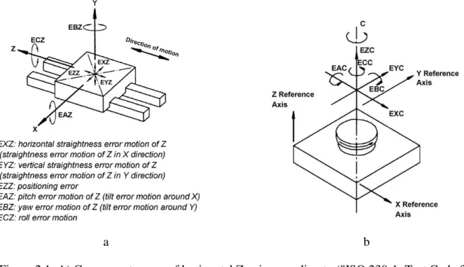
Schwenke et al. (Schwenke et al., 2008) presented a general view of different sources of machine tool geometry errors including kinematic errors, thermo-mechanical errors, load, dynamic forces and motion control. They also presented some fundamental errors components. For example, for a nominally linear motion there are six motion error components including two tilt error motion, roll error motion, two straightness errors motion and a positioning error (Figure 2.1 A). Each rotary axis also has six errors motion including two radial errors motion; the axial error motion, the angular position error and two tilt errors motion (Figure 2.1 B).
a b
Figure 2.1: A) Component errors of horizontal Z axis according to ("ISO 230-1: Test Code for Machine Tools. Geometric Accuracy of Machines perating Under No-Load or Finishing Conditions, ISO, Geneva.," 1996) B) Location errors of C axis average line (Schwenke et al.,
2008)
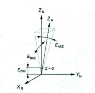
On the other hand, for each liner axis there are two squareness errors and the zero position error (Figure 2.2). Similarly, for a rotary axis there are also two translational errors in addition to the ones of a linear axis as shown in Figure 2.2
Figure 2.2: Link errors of a linear axis, Z ("ISO 230-1: Test Code for Machine Tools. Geometric Accuracy of Machines perating Under No-Load or Finishing Conditions, ISO, Geneva.," 1996)
2.3
Volumetric error
All geometrical errors related to machine tools including motion errors and link errors affect the relative position of the tool inserted on the machine spindle and the work-piece hold on the machine table. This discrepancy is presented as the term “volumetric error” referring to the resulting error in position and orientation of the machine tool end effector (tool or stylus tip) related to the workpiece or feature to be machined or measured. Volumetric error is defined in the working space of the machine tool and can be measured using calibrated artifacts or telescoping ball-bar. Volumetric errors affect both the machining and metrological performance of the machine tool. So, to evaluate the machine tool on-machine-measuring performance volumetric errors should be taken into consideration.
The volumetric errors include two main categories. Firstly, dynamic errors caused by the machine’s servo motors and secondly, static or geometric errors include the joints and links geometric errors caused by imperfect geometry of the guideways and structural components, etc. (R. J. Hocken, 1980) .
Slamani et al. (Slamani et al., 2010) presented a technique to assess a machine tool volumetric errors including both the dynamic and static errors and then compared the influence of geometric errors and dynamic errors at different machining feed rates.
2.4
Error evaluation approaches and devices
There are generally two approaches to evaluate machine errors. One approach is direct measurement which is used to measure an individual axis errors one at a time such as positioning errors, straightness errors and angular errors for a single axis and squareness error between two axes. The indirect approach measures the effect of combined errors which are then decoupled through mathematical modeling. Different common standard parts and devices are now presented for calibration and errors estimation of machine tools and CMMs.
Standard artifacts such as straightedges, line scales (Guideline, 1986) or step gages and even multidimensional artifacts like ball plates and laser-based methods are the common direct measurement methods.
Step gauges are mostly used to check linear positioning errors and to conduct verification and acceptance tests on CMMs (Abbaszadeh-Mir, Mayer, Cloutier, & Fortin, 2002).
Laser interferometer systems are also common systems specially to calibrate the MTs. As an example Castro et al. (Castro & Burdekin, 2003) presented a method for evaluating the positioning accuracy of machine tools and coordinate measuring machines (CMM) under dynamic condition using a laser interferometer which is capable of performing dynamic calibration. Another approach for mapping of geometric errors of machine tools and CMMs used a single tracking interferometer based on interferometric displacement measurements between fixed reference points on the base and fixed offset points on the spindle (Schwenke, Franke, & Hannaford, 2005). Generally, all laser interferometers are so sensitive to environmental condition and their first setup is time consuming. On the other hand, contour measurement (Sciammarella, 2013), multi-lateration measurement (Zou, 2016) and chase-the-ball measurement (Bringmann & Knapp, 2006), (Ezedine, Linares, Sprauel, & Chaves-Jacob, 2016) are some examples of indirect measurement approaches. Ball bar methods such as telescopic magnetic ball bar are common methods to verify geometric errors in both MTs and CMMs. There are two common types of magnetic ball bars including fix and telescopic. The general simulation and theory to identify five-axis machine tool geometrical errors by using telescopic magnetic ball bar is explained by Abbaszadeh-Mir (Abbaszadeh-Mir et al., 2002), in this method the distance between a ball rigidly attached to the spindle and another ball rigidly attached to the workpiece table are measured, then by considering the machine tool geometry a Jacobian matrix is calculated which is then used to estimate the errors parameters.
Either calibrated, partially calibrated or un-calibrated artifacts may be used in indirect methods. Machine tool geometric error parameters can be defined by using a reconfigurable un-calibrated artefact and developing a mathematical model to remove the effects of unknown artefact geometry by compensating them (Erkan, Mayer, & Dupont, 2009). RUMBA method presented by T. Erkan et al. (Erkan, Mayer, & Dupont, 2011) uses several un-calibrated master balls fixed on the rotary table to identify both the position and the orientation axes errors and some other motion errors of a 5-axis MT by measuring relative position between balls and machine tool work-piece table. Plate type artefacts are also used commonly to measure positioning errors of machine too. Plate type artefacts such as ball plate (Liebrich, Bringmann, & Knapp, 2009), (Guenther, Stobener, & Goch, 2016), hole plate (Lee & Burdekin, 2001) and cone plate are developed based on measuring holes, balls or cones center distances. In general, hole plates accessibility are more limited than ball plate accessibility and they are used often for 2-D measuring, on the other hand, they are less sensitive and more reliable in term of plate bending. The design of the ball plate is highly sensitive to the clamping system and force, causing significant mechanical deformation that directly affects the position of spheres which are supposed to be fixed (Lee & Burdekin, 2001). To verify CMM performance, calibration is applied by using reversal technique and then probing on four different positions on the machine; by calculating the residual between measured and calibrated position of each ball on the CMM.
Bringmann et al. presented a new measuring artefact consisting of a standard 2D-ball plate that can be relocated to achieve a pseudo 3-D artefact providing a fast and reliable method to test and calibrate 3 axis machine tools and CMM (Bringmann & Kung, 2005). Using kinematic coupling in this project provided a reliable repeatability for the artefact measurement. In order to eliminate the effect of CMM geometrical errors artefact should be calibrated by probing in different horizontal and vertical positions. (Liebrich et al., 2009)
Generally, using ball-artefact based methods for the purpose of machine tool calibration and to evaluate the machine metrological performance could be proposed as an alternative for time consuming methods such as laser interferometer, provided that a sufficient probing method be defined to measure the balls center. The common method is using machine-integrated touch trigger probes, but in this case numerous touches are needed to determine a ball center which is relatively time consuming, thus self-centering probe system (Yague et al., 2009) is developed using a
specifically designed ball-measuring 3D probe which is able to measure each ball center only in one measuring step. This new probe concept includes 3 linear probes positioned in a three orthogonal styli configuration. The negative point of this approach is that because of its huge configuration the probing accessibility is reduced.
Recently, Bringmann et al. (Bringmann & Kung, 2005) presented an artefact for machine calibration and explained some necessary conditions to take into consideration for the development of an artefact to minimize measuring steps and operation time, including:
-the device should provide accessibility to measure deviation through all 3 linear axes;
-the artefact target points should be distributed uniformly through the whole machine tool workspace;
-the uncertainty of the measurement device should be considerably less than the tolerance for the geometric machine deviations.
2.5
On-Machine measurement
The technique of on-machine measurement allows the machine tool to be used for both machining and inspection purposes with the aim of reducing the total cost and cycle time. By using on-machine measurement approach as a simple alternative mechanism for verifying part geometry the inspection capability information generated by on-machine acceptance processes can be available for designers that help them to create a design-for-inspect ability environment (Pancerella, Hazelton, & Frost, 1995).
Probing errors of a touch probe and positioning errors of the machine tool, inevitably affect the measuring results. So to obtain true measuring results achieved by on-machine measurement these errors should be taken into account or compensated (Choi, Min, & Lee, 2004). Generally there are two different techniques for on-machine measurement, the first method which is more popular is using a touch trigger probe similar to what is used on CMMs, and the second one recently developed are non-contact techniques.
A vision-based on-machine measurement system is a recently developed method to improve manufacturing productivity. It is a visual probe that enables the machine tool itself to be applied as a CMM to measure and inspect a workpiece (Xia, Han, Lu, & Xia, 2015). It is composed of a visual
probe and some software to process the measuring and inspection data. The auto-focus function of the visual probe was realized using the astigmatic method.
On-machine measurement is very demanded in large components machining because usually to hold these components during machining special fixtures are needed. Removing from the machine tool and then fixturing for loading on a CMM, parts dimensions can be changed enough for a good part to be rejected. There are different approaches to achieve traceable large volume metrology (LVM) processes in different fields of large volume manufacturing. Integration of the measurement process into large machine tools seems to be an ideal solution to improve the quality and reduce waste material and a better conformance with the tolerances required. Especially the development of one clamping set up allows machining and measuring in the same coordinate system and consequently improves the product quality (Schmitt, 2013).
To improve the productivity of large-parts manufacturing a new on-machine procedure is presented by Uekita (Uekita & Takaya, 2016) which consists of a laser tracker as the length-measurement apparatus, a probing unit, and a length-calibrating artefact to establish a traceable and automated measuring procedure. The machine tool volumetric errors should be taken in to account to achieve the exact dimension for the target part.
CHAPTER 3
PROCESS FOR THE RESEARCH PROJECT AND
METHODOLOGY
To meet the increasing demand for parts with high precision, precise machine tools with measuring capability are sought. The objective of this thesis is to evaluate the machine tool coordinates measuring performance by using a newly designed 3-D artefact named dome artefact. The following steps describe the outline of undertaken steps to fulfill this objective:
3.1
Artefact design:
- Design a new 3-D artefact based on a pseudo hemisphere shape; - Made the artefact of Invar to reduce the effect of thermal expansion.
3.2
Measuring the artefact on a Coordinate Measuring Machine (CMM):
- Evaluating the CMM measurement repeatability.
- Evaluating the measurement repeatability for various clamping torque.(Clamped measurement repeatability)
- Evaluating the effect of various artefact orientations relative to local gravity.
- Defining a compliance model to reduce the effect of gravity in different orientations.
3.3
Transferring the artefact to the Machine tool
- Calculating the position of each ball relative to machine tool work piece table using simulator program.
- Implementing on-machine measurement non-involving machine tool rotary axes to simulate the CMM configuration.
- Comparing the on-machine measurement results and the calibrated model to evaluate the machine tool coordinate measuring performances for various B and C indexations.
3.4
Defining the measurement uncertainty:
- Artefact geometry repeatability - Clamping geometry repeatability - Gravity compliances model
CHAPTER 4
ARTICLE 1: A BALL DOME ARTEFACT FOR
COORDINATE METROLOGY PERFORMANCE EVALUATION OF A
FIVE AXIS MACHINE TOOL
J.R.R. Mayer (2)*, Heidarali Hashemiboroujeni, accepted in CIRP Annals Manufacturing Technology 2017
4.1
Abstract:
Five-axis machine tools are increasingly used for coordinate metrology on workpieces at various stage of machining. Evaluation of the metrological capability in five axis mode using a probed reference artefact requires accessibility from various probing directions. When rotary axes handle the artefact its deflection under varying gravitational loading is also a concern. A 3D artefact is proposed consisting of a kinematically mounted Invar structure dome holding 25 precision balls. The effect of changing gravity on its geometry is quantified and it is then used to evaluate the coordinate metrology capability in five axis mode of a wCBXfZYt topology machine tool.
Key words: Machine tool, Measurement; Accuracy
4.2
Introduction
Touch trigger probes, and now scanning probes, are used on machine tools for such tasks as table and workpiece locating prior to machining and compensation for tool and workpiece deflection using intermittent probing [1]. Assessing the conformity of a finished part using the machine tool as a coordinate measuring machine is also of interest. In [2] the uncertainty was estimated for a particular measuring task by measuring a calibrated workpiece with a 80 mm hole when using the three linear axis of a machine considering the impact of thermal effects. Recent standards suggest estimating measurement uncertainty using a calibrated workpiece similar to the one of interest [3] or using a virtual model and simulations [4]. A general artefact was proposed, and its uncertainty estimated, for testing and calibrating a three axis machine tools using a pseudo 3D grid built from a kinematically relocated 2D ball plate [5]. In [6] the individual probing on a single ball for a number of rotary axes indexations on a five-axis machine tool are assembled into a common reference frame to analyse the apparent out-of-sphericity and size. When machining a part using
the rotary axes of a five axis machine tool it is likely that verifying such tolerance as positioning also requires combining measurements made for different indexations of the rotary axes. On a coordinate measuring machine (CMM) whenever there is a change in the indexation of the probe head the stylus tip centre position changes relative to the machine reference frame. As a result it is necessary to re-measure the centre coordinates of a reference sphere which position does not change relative to the part being measured. On a five-axis machine rotary axes may change the orientation of the workpiece relative to the x, y and z axes of the machine tool. Unless at least three spheres fixed relative to the workpiece are re-measured for each such re-indexation, it is necessary to use computations to express all stylus tip touch positions into a common reference frame rigidly connected to the last axis of the workpiece branch such as the workpiece, workpiece table or the last axis frame. Such calculations require the position of the stylus tip relative to the spindle as well as the kinematic model of the machine, either using nominal geometric parameters values or calibrated ones [6].
4.3
The ball dome artefact
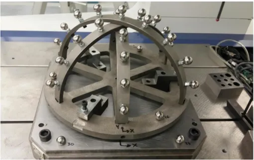
The tested five-axis horizontal machine tool has two rotary axes holding the workpiece and a wCBXfZYt topology. A maximum number of balls must be accessible for probing for the full range of motion of the two rotary axes. The artefact uses arcs of equal thickness but slightly different radii, and balls, on constant length stems, located on a quasi-hemisphere. All balls are accessible for the full B-axis range of -90≤b’≤+90, by rotating the C-axis. The fabricated ball dome artefact is shown in Figure 4.1.
Figure 4.1: Photos of the ball dome artefact (left) and loaded on the C-axis of the machine tool ready for probing (right)
It was anticipated that the three main factors affecting the artefact geometry would be thermal expansion due to the machine workspace temperature, non-repeatable deformation from clamping and finally the elastic deformation of the artefact under varying gravitational forces due to the rotation of the C-axis on this horizontal machine tool.
In order to limit thermal expansion and distortion, the artefact structure is made of Invar. The balls and short stems are made of steel. The artefact is kinematically fixtured to the machine table via a supplemental steel mounting plate fitted with three V-supports. The artefact has three similarly located steel hemispheres. The fixturing forces are applied, using screws and a controlled tightening torque, near the kinematic supports in order to limit deflection in the artefact structure. The artefact structure uses three semi-circular arches joined at both ends to a common ring and attached together at their mid-points.
This paper presents the design, calibration and use of the ball dome artefact to quantify the ability of a machine tool for coordinate metrology in five-axis mode.
4.4
Ball dome artefact calibration and evaluation
A number of test were conducted on a Mitutoyo Legex 910 with a Renishaw TP7M probe and a 50 mm long probe extension bar model PEM1, a stylus length of 150 mm and a stylus tip of 6 mm diameter. In accordance with ISO10260-2:2001 the CMM has a P value of 1.3 µm and a maximum E value of 2.9 µm for the used volume. The tests have three objectives. The first objective is to
assess the repeatability of the CMM measuring process. The second objective is to quantify the repeatability of the geometry of the artefact, i.e. the relative position of the balls of the dome, in the clamped state so that it can be calibrated on a CMM and then unclamped, moved to the machine tool and re-clamped. The third objective is to quantify the variation in the position of the dome balls when the table, and artefact, are rotated in a way that changes the direction of gravity. The artefact has 25 balls on its dome and three more on its base ring. Another four balls are directly attached to the interface plate for a total of 32 balls. Four setups were studied:
- Horizontal position (H): the artefact is clamped on the workpiece table horizontally i.e. table normal pointing upwards relative to gravity;
- Horizontal position rotated (HR): as for H but the whole assembly (artefact and table) is rotated by 90 around a vertical axis. This should not alter the assembly but changes the association of the CMM systematic errors with the various balls;
- Vertical position (V): the assembly is tilted so that the table normal is perpendicular to gravity i.e. as on the machine tool;
- Vertical position rotated (VR): the assembly is rotated by 90 around a horizontal axis, which is similar in action to a C-axis rotation on the machine tool, so that the action of gravity changes again relative to the artefact.
4.5
Measurement repeatability
Let’s say a ball center coordinate measurement is pi,j,k where i, j and k are the identifiers for the ball, setup and repetition respectively. Measurement of all Ni=32 balls was repeated Nk=3 times for all four setups. For each ball and each setup a mean ball position is calculated. Then standard deviations are calculated for each ball and setup and finally a pooled standard deviation is calculated for each setup separately and for all setups together.
Nk i,j i,j,k k 1 1 N k
p p ; pi,j,kpi,j,kp ; i,j di,j,k pi,j,k (1)
k i i N N 2 k 2 i,j,k d,i,j 1 1 d,i,j p,d,j N k k 1 (N 1) ; (N 1) (N 1) k i i d s s s . (2)Table 4.1 shows that the largest pooled deviations for a setup and the overall pooled standard deviations are 0.59 and 0.53 µm respectively.
Table 4.1: Repeatability of measurements as pooled standard deviations (in µm)
4.6
Clamping repeatability
The clamped geometry repeatability is essential so that the artefact can be pre-calibrated clamped and then transferred to a machine tool and re-clamped. The clamped geometry repeatability is verified by comparing the two sets of ball center coordinates for two successive clamped states as follows: mount on the kinematic receptacle, clamp, measure, unclamp, remove and remount, re-clamp, re-measure. A 3D rigid body cloud point fit is conducted using the method described in [8] adapted to minimize the sum of the square of the coordinate differences between the two sets of points as follows:
2 , ,sec argmin , , , , ,i first clamping i ond clamping
p p
x y z
.
(3)
Three tests were conducted using different tightening torques for the kinematic mount screws (visible in Figure 4.1 (left)). Controlled tightening torques of 10 and 5 lb-ft were tested. The detailed results in Table 4-2 are calculated using similar equations to (1) and (2) for each torque level. The worse change amongst the 28 artefact balls and amongst the two torques was 2.2 µm and the worse pooled standard deviation was 0.58 µm.
Table 4.2: Repeatability of the clamped geometry of the ball dome artefact: maximum distance and pooled standard deviation (in µm)
Setup
H HR V VR Overall
Sp,d 0.46 0.57 0.59 0.49 0.53
Torque 10 (lb-ft) 5 (lb-ft)
Maximum distance, dH,Max 2.2 1.8
4.7
Gravitational loading
On many five axis machine tools the rotary axes may alter the orientation of the mounted artefact relative to local gravity. This effect is quantified as a systematic error represented by the ball center shift and its norm for each ball between setups. The ball coordinates are in a reference frame constructed from three of the four balls attached directly to the interface plate which three balls are expected to be much less affected by gravity. The setups are compared in two pairs: H and V, and, V and VR. As an example the V-H values are obtained as follows:
i,V-H i,V i,H V-H Ni i,V-H i 1 1 ; Ni p p p p p (4) Ni
i,V-H i,V-H V-H i,V-H 1 1 ; Ni i d p d d . (5)
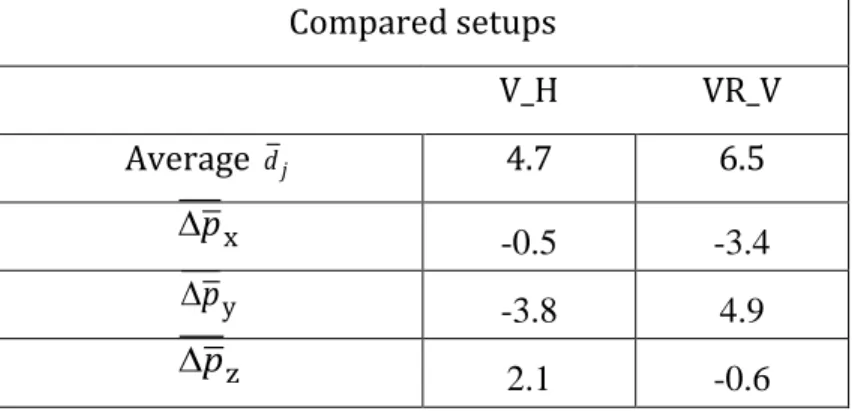
The results in Table 3 indicate that the largest changes in the position of a ball relative to the table occurred between the vertical rotated and vertical setups and reach average and maximum values of 6.5 and 9.3 µm respectively. shows that the change in the direction of gravity from -z to -y for the setup V-H causes the expected slight shift of the balls towards +z and -y. The rotation from V to VR is around an axis perpendicular to gravity and is similar to a C-axis rotation by 90 on the target machine. In this case, the direction of gravity changes from -y to -x. Figure 4-3 shows that the change is primarily in the xy plane and is consistent with the change in the direction of gravity direction.
Table 4.3: Change in the position of the balls of the clamped artefact under changing orientation relative to gravity (in µm)
Compared setups V_H VR_V Average dj 4.7 6.5 p x -0.5 -3.4 py -3.8 4.9 p z 2.1 -0.6
Table 4.3 (cont’d): Change in the position of the balls of the clamped artefact under changing orientation relative to gravity (in µm)
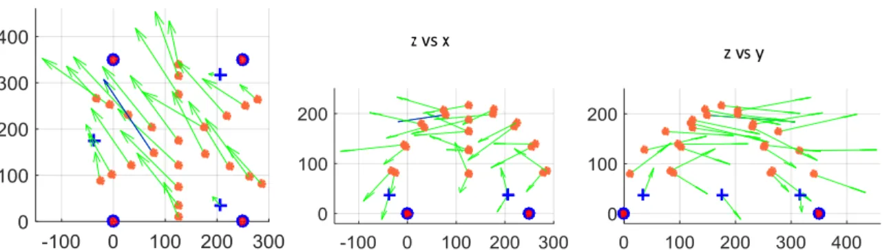
Figure 4.2: Change in ball positions when moving the table and artefact form a horizontal to a vertical orientation (V-H). For the H and V setups gravity points towards –z and –y respectively
(errors vectors 20000) Maximum, 7.4 9.3 -1.5 -4.7 -7.0 8.0 1.8 -0.7 j,max d pV-H,x,max pV-H,y,max pV-H,z,max
Figure 4.3: Change in ball positions when moving the table and artefact form by 90 while remaining in the vertical orientation (VR-V). For VR and V gravity points in –x and –y
respectively (errors vectors 20000)
Given that gravity has a significant systematic effect, and awaiting stiffeners to be added to the artefact, corrections were applied using compliances individually estimated for each ball on the basis of these observations. Such corrections are applied to the mean H setup results to predict the actual geometry of the artefact when mounted and rotated on the machine tool.
Considering the CMM performance, the artefact measurement repeatability on the CMM, the clamped geometry repeatability and the gravitational correction, the expanded combined uncertainty on the calibrated center position of the balls center relative to a reference frame fixed to the machine table, and after clamping, mounting in the vertical position and rotation around the C-axis is estimated at 5.3 µm (k=2).
4.8
Five-axis coordinate metrology
Each ball is probed to establish its center coordinates and the corresponding axes positions (x, y, z, b and c) are recorded. For x=y=z=0 the stylus tip center is nominally positioned at the intersection of the B and C axes. In this work the functional point [9] is the position of the stylus tip calculated relative to a reference frame attached rigidly to the workpiece frame but with its origin on the C-axis and its z-C-axis corresponding to the C-C-axis. The ability to measure geometrically coherent positions in this frame is relevant to the ability of the machine to conduct five-axis metrology. The position of the stylus tip in this last workpiece branch axis frame, here the C-axis frame, is calculated as follows:
C C B X f Z
B X f Z Y
tip
where T T C C C C tip x, y, z, 1 ; x y z, , , 1
p tip tip tip t t t t
. (7)
[9]), nominal axis motion and intra-axis errors (called error motion in [9]) the homogenous transformation matrices of Equation (6) are expanded as follows as an example for axis Y:
N A A A N 0 0 A N A N A 0 0 Y Y ZTY ZTY TY TY YTY (8)
with 0, N and A standing for ‘zero motion’, ‘nominal’ and ‘actual’ respectively. These four sub-matrices are as follows:
A N 0 N A 0 0 3 3 C 0X Y A 0Z Y Z Y Y Y 1 3 1 3 0 0 ˆ, ˆ, 0 I 0 ; 0 0 0 1 0 1 R k E R i E T T (9)
0 XY CY BY AY YY 3 3 Y Y Y Y* ZY 1 3 1 3 0 ˆ, ˆ, ˆ, I ; 0 0 1 0 1 A E R k E R j E R x E E y T T E (10)where R is a 3x3 rotation matrix. Error notation is as in [9].
4.9
Machine tool performance for five-axis metrology
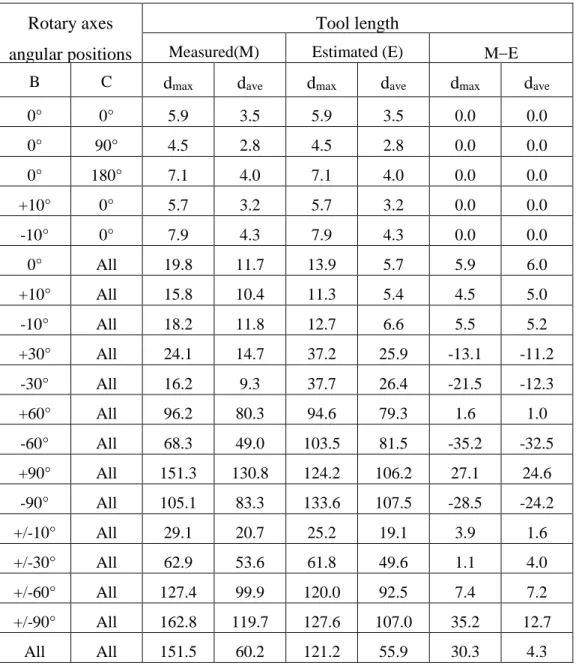
The artefact was clamped in the horizontal position in the machine pallet changer area and then automatically loaded vertically in the machine working area onto the C-axis as shown in Figure 1 (right). A number of tests were conducted which gradually increased the involvement of the rotary axes in the measurement process. A total of 613 ball centers were measured in about 15 hours. For each test all machine tool measured (MTM) positions of the ball dome artefact balls center coordinates are calculated and brought to a common frame using Equation (6) assuming zero inter- and intra-axis errors. They are then compared to the CMM measured ones using cloud point fitting in order to only consider the geometry of the artefact. The distances between the CMM and MTM ball centers are calculated and the maximum and average values are presented in Table 4.4.
The tool is nominally defined by its length, as measured using a tool setting instrument, and zero lateral offsets are assumed. Looking at the results for the nominal tool, in the first two columns, it is noticeable that results are best, 7.9 µm at worst, when all measurements are made without combining information from different angular positions of the rotary axes. In this case, the five axis machine tool is used as a three axis machine. For b=0 and combining data from all three angular positions of the C-axis (i.e. 0°, 90°, 180° and 360°) the worst case error increases to 19.8 µm. In this case, in addition to any error from the C-axes, different volumetric errors due to the XYZ-axes are associated to a ball when it is re-measured for a new angular position of the C-axis. For constant, but non zero, angular positions of the B-axis from -90° to +90° the errors generally increase and vary between 15.8 to 151.3 µm. This is attributed to a large EX(0B)C (B to C cross-axis offset) on this machine. This error creates an offset on the ball center coordinates which changes direction in the artefact frame (attached to the frame) with angular positions of the C-axis. Using two opposite values of the B-axis from +/-10 to +/-90 results in larger errors, up to 162.8 µm.
The third and fourth column results are calculated using an estimated tool definition obtained by processing all the available data as in the RUMBA method [10] but only estimating the ball positions and the tool length and lateral offsets. The objective being to find the ball and tool positions which best explain the gathered machine axis position corresponding to the stylus tip being at the centers of the balls. The ball positions are assumed unknown for this estimation. Then, only the tool value is retained for further processing using Equation (6). Results in suggest that the tool definition has no effect when the rotary axes are not involved in the measuring process. For b=0 and combining data from all three angular positions of the C-axis the average error is reduced by a half from 11.7 µm down to 5.7 µm. When using a single non-zero B-axis angular position and all three C-axis angular positions the results are sometimes better sometimes worst especially for negative B values. When using two opposite values of the B-axis from +/ 10 to +/ 90 and when using all available data the new tool value produces a better MTM geometry for the artefact. It is thought that the estimated tool attempts to correct the effect of the large EX(0B)C value which is most of the time, but not always, helpful.
Table 4.4: MTM versus CMM coordinates (in µm) for various combinations of rotary axes angular positions using the measured probing tool length or an estimated probe definition
Rotary axes angular positions
Tool length
Measured(M) Estimated (E) ME
B C dmax dave dmax dave dmax dave
0° 0° 5.9 3.5 5.9 3.5 0.0 0.0 0° 90° 4.5 2.8 4.5 2.8 0.0 0.0 0° 180° 7.1 4.0 7.1 4.0 0.0 0.0 +10° 0° 5.7 3.2 5.7 3.2 0.0 0.0 -10° 0° 7.9 4.3 7.9 4.3 0.0 0.0 0° All 19.8 11.7 13.9 5.7 5.9 6.0 +10° All 15.8 10.4 11.3 5.4 4.5 5.0 -10° All 18.2 11.8 12.7 6.6 5.5 5.2 +30° All 24.1 14.7 37.2 25.9 -13.1 -11.2 -30° All 16.2 9.3 37.7 26.4 -21.5 -12.3 +60° All 96.2 80.3 94.6 79.3 1.6 1.0 -60° All 68.3 49.0 103.5 81.5 -35.2 -32.5 +90° All 151.3 130.8 124.2 106.2 27.1 24.6 -90° All 105.1 83.3 133.6 107.5 -28.5 -24.2 +/-10° All 29.1 20.7 25.2 19.1 3.9 1.6 +/-30° All 62.9 53.6 61.8 49.6 1.1 4.0 +/-60° All 127.4 99.9 120.0 92.5 7.4 7.2 +/-90° All 162.8 119.7 127.6 107.0 35.2 12.7 All All 151.5 60.2 121.2 55.9 30.3 4.3
Figure 4.4 and Figure 4.5 show the amplified volumetric error vectors at each ball for the b=0, c=0, 90, 180, 360 pairs and for all b and c angular position pairs respectively. Note that errors are 20 times less amplified in Figure 4.5. Errors on Figure 4.5 are dominated by the cross-axis offset which effect is in the XZ plane of the machine frame but due to the C-axis rotation changes direction in the artefact frame.
4.10 Conclusion
The ball dome artefact supporting 25 balls on a quasi-hemispherical envelop was fabricated of Invar and fixtured using kinematic supports. The repeatability of clamping and deflection due to a changing gravity vector were quantified and found to be on average of the order of 0.6 and 6.5 µm respectively. A detailed analysis of the effect of tilting the artefact from a horizontal to a vertical orientation suggests that adding stiffness could further reduce gravity induced errors. However, ball specific corrections were applied based on the observed compliances. Artefact ball center uncertainty once mounted on the machine tool is estimated at 5.3 µm (k=2). The new artefact allows the full range of rotary axis motion of the wCBXfZYt machine to be used in evaluating the machine for up to five axis coordinate metrology. When using only the linear axes of the machine tool a worst case measurement error of 7.9 µm is obtained. This value increases to 19.8 µm when the C-axis is involved but can be reduced to 13.9 µm when an estimated tool definition is used to process the data. The worst case error increases to 162.8 µm when both the C- and B-axis are used. This is attributed to the presence of a large EX(OB)C error on the machine tested.
4.11 Acknowledgments
Authors are grateful for the technical support of Guy Gironne in constructing and measuring the artefact on the machine tool and on the CMM. Work was in part financed by NSERC.
Figure 4.4: Differences between the MTM and CMM dome artefact ball centers using four axis (X, Y, Z and C-axis) and an estimated tool; 10000
Figure 4.5: Differences between the MTM and CMM dome artefact ball center positions when using all five axes and an estimated tool; 500
References
[1] R Guiassa, JRR Mayer, Predictive compliance based model for compensation in multi-pass milling by on-machine probing, CIRP Annals - Manufacturing Technology, 60(1) 391-394, 2011.
[2] R Schmitt, M Peterek, Traceable measurement on machine tools – thermal influences on machine tool structure and measurement uncertainty, 9th CIRP Conference on Intelligent Computation in Manufacturing Engineering - CIRP ICME '14, 23- 25 July 2014, Capri (Naples), Italy, Procedia CIRP, 33(2015) 576–580.
[3] ISO 15530-3:2011(E), Geometrical product specifications (GPS) – Coordinate measuring machines (CMM) – Technique for determining the uncertainty of measurement – Part 3: Use of calibrated workpieces or measurement standards.
[4] ISO/TS 15530-4:2008(E), Geometrical product specifications (GPS) – Coordinate measuring machines (CMM) – Technique for determining the uncertainty of measurement – Part 4: Evaluating task-specific measurement uncertainty using simulation
[5] B Bringmann, A Kung, A Measuring Artefact for true 3D Machine Testing and Calibration, 54(1), 2005, 471-474.
[6] T. Liebrich, B. Bringmann, W. Knapp, Calibration of a 3D-ball plate, Precision Engineering 33(2009) 1-6.
[7] Md Mizanur Rahman, R Mayer, Performance of a five-axis machine tool as a coordinate measuring machine (CMM), Journal of Advanced Mechanical Design, Systems, and Manufacturing, 10(5), 2016.
[8] P Bourdet, A Clement, Controlling a Complex Surface with a 3 Axis Measuring Machine, Annals of the CIRP, 25(1), 359-361, 1976.
[9] ISO 230-1:2012, Test Code for Machine Tools. Part 1: Geometric Accuracy of Machines Operating Under No-load Conditions.
[10] JRR Mayer, "Five-axis machine tool calibration by probing a scale enriched reconfigurable uncalibrated master balls artefact," CIRP Annals - Manufacturing Technology, vol. 61, pp. 515-518, 2012.
CHAPTER 5
COMPLEMENTARY TECHNICAL DETAILS
This chapter, a complementary explanation to the materials and methods provided in the paper presented in chapter 4 is provided.
Using an artefact supposed to be calibrated on a CMM is considered to evaluate the metrology performance of a five-axis horizontal machine tool by comparing the coordinates measured on the CMM with the ones achieved by the machine tool.
In order to have a reliable measurement, the geometrical stability of the artefact under different clamping conditions and the effect of gravity on the artefact structure under varying gravitational directions should be taken into consideration.
5.1
Artefact stability
Coordinate measuring machines often are located and used in temperature controlled and clean areas. On the other hand, a machining shop or where ever a machine tool is working in, ordinary does not have that level of standards for environment considerations. Moreover, the machine tool operation, regardless of cutting or milling process, generates heat and thermal flow by itself, so stabilizing the machine tool temperature during the machining or measuring is impracticable. To reduce the effect of thermally induced deformation on the artefact geometry there would not be any choices unless using a thermo-invariant material. As explained in the paper the material which is used in this research is Invar, also known generically as FeNi36 (64FeNi in the US), which is a nickel–iron alloy notable for its uniquely low coefficient of thermal expansion (CTE or α). The name Invar comes from the word invariable, referring to its relative lack of expansion or contraction with temperature changes.
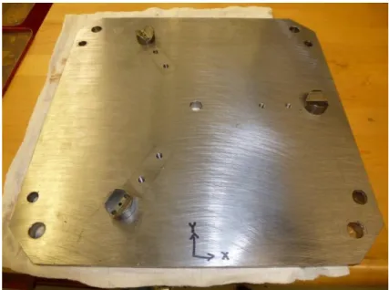
As it is explained the artefact is supposed to be measured and calibrated on a coordinate measuring machine and then be transferred to the machine tool to be measured again, which needs clamping, unclamping, picking up, transferring and putting back the artefact. So the artefact measurement repeatability is critical parameter to take into account while transferring the artefact. To provide a reliable installation approach that allows the artefact to be located at the exact position, some kinematic joints are used include 3 standard hemispheres which are supposed to be seated on 3 standard V-blocks (Figure 5.2). Using kinematical coupling is a common way to provide a reliable and repeatable positioning.
The first model is designed and simulated on NX-Unigraphics (Figure 5.1) and then it is imported to Catia to provide an integrated model for machining.
Figure 5.1: The artefact model designed on NX
Figure 5.2: Three V-blocks attached to the base plate to provide a stable seat place for the artefact As artefact is going to be used on a horizontal milling machine which has a vertical work-piece table, the artefact should be hold and fixed on the machine vertical table to prevent falling down, so clamping the artefact is unavoidable (Figure 5.4). Because of elastic intrinsic quiddity of metals, the artefact structure especially the ring part will be deformed under clamping force which causes
deviation on whole artefact configuration, so the effects of clamping on various positions and different clamping forces are evaluated.
Figure 5.3: Clamps configuration
Optimized torque volume not only is able to hold the artefact properly on the kinematic joints to provide reasonable measurement repeatability, but also minimizes the elastic deformation caused by clamping force.
Another important factor that affects the artefact stability is the gravitational force, in other word, the artefact weight. The coordinate measuring machine which is used for this research project is Mitutoyo Legex 910 which has a horizontal work-piece table. Ordinary, the artefact is supposed to be placed on the machine table horizontally to be probed. On the other hand, the machine tool subjected is a horizontal five axis machine tool which has a vertical work piece table, so the artefact is supposed to be placed in vertical direction. In this research, by using an auxiliary table placed vertically on the main CMM table, a similar configuration as the machine tool work piece table is replicated for the CMM. So by putting the artefact on this new vertical table, the CMM will be able to probe and measure the artefact while it is located in vertical position (Figure 5.5). Then, by comparing the results come from probing the artefact in both horizontal and vertical positions on the CMM, the artefact stability considering re-orientation relative to local gravity is evaluated.
Figure 5.5: Artefact located in vertical position
5.2
Artefact design:
In geometrical point of view, the intended artefact for this research is designed pretty large to cover a major portion of machine tool working space. Also, it is extended almost uniformly relative to machine tool rotary axis (C axis).
The designed hemisphere artefact includes a base ring which holds 3 Semi-circular arcs with different radius which are attached together at the midpoint (Figure 5.6) where they pass exactly
over each other without considerable offset, means that the radius differences equal to the arcs thickness. So, balls installed on the arcs with the same stem length will be located on different distances from the ring center point.
Figure 5.6: Attaching the arcs together in the mid-point
To have target points which are supposed to be probed, 25 standard stainless steel balls are installed on the arcs equally spaced, 9 balls on each arc, and the center ball is shared between 3 arcs. In designing the artefact, it is tried to provide the maximum number of balls accessible to probe for a maximum range of motion of the both machine tool rotary axis. Figure 5.8 shows the machine tool workpiece table and the artefact.
Figure 5.7: Five-axis machine tool (wCBXFZYSt) as a kinematic chain
As it is mentioned, estimating the effects of clamping force is also interested. To be able to observe the clamping effect directly on the ring, 3 balls are directly installed on the ring to be probed. By using 3 kinematic V-blocks and 3 truncated and threaded balls, artefact placed on the base plat which is attached directly to the machine tool table (pallet) using four bolts. According to the test procedure, the artefact is probed on both clamping and unclamping positions, as well as both horizontal and vertical positions. In all these positions, it is supposed that the base plate which is attached to the machine table is stable and rigid and can be used as a measuring reference. So by defining four points on the base plat, a reference coordinate system is defined (3 points to define the reference frame and one point reserved to check). These points actually are the center of balls which are attached to the base plate in a rectangular position relative to each other. After defining the coordinate reference frame, all other balls center coordinate relative to the machine tool or CMM frame will be transferred into this new defined common reference frame.
5.3
Measurement uncertainty:
Uncertainty (of measurement) parameter, associated with the result of a measurement, that characterizes the dispersion of the values that could reasonably be attributed to the measurand (Standardization, 2008).
Uncertainty of a measurement comprises many components. Some of these components may be evaluated from the statistical distribution of the results of series of measurements and can be characterized by experimental standard deviations. The other components which also can be characterized by standard deviations are evaluated from assumed probability distributions based on experience or other information.
In this case, CMM measurement repeatability is quantified and the measurement uncertainty is defined. Moreover, uncertainties of the artefact repeatability and clamping repeatability are determined as well. The artefact is measured several times at the same configuration, then the average position for each ball is calculated, so the residual is defined as the deviation between measurand position and the average position. By calculating the standard deviation of those residuals the uncertainty value is achieved.
Other parameter that is interested is the effect of gravity, in other words, the effect of gravity while the artefact is located on various orientations relative to local gravity direction. By comparing the
balls coordinate measured on the CMM while it is measured on different positions such as horizontal, horizontal rotated, vertical and vertical rotated, a compliance model is proposed to correct the effect of gravity. It means that by calculating the compliances parameters in X, Y and Z directions arranged in a matrix form and considering the C axis rotation angle and the reference model comes from horizontal probing, the calibrated model for vertical position in various C axis indexations will be estimated. The uncertainty of the compliance model is also calculated by calculating the standard deviation of residual between the estimated model and measured model for vertical and vertical rotated positions.
At the end, considering the CMM performance uncertainty, the artefact measurement uncertainty, the clamping repeatability uncertainty and the uncertainty characterized for gravity compliances, the total uncertainty for balls position measuring is calculated.
5.4
Results:
In this section, all the measuring results which are used in the paper (Chapter 4) are presented in details.
5.4.1 CMM vertical and horizontal probing:
The maximum absolute deviation and maximum deviation for each X, Y and Z directions as well as average deviation for 3 times probing results while the artifact located at the same position are presented in Table 5.1.
Table 5.1: Maximum and average deviation Maximum deviation
(Milimeter) Horizontal
Horizontal
rotated Vertical Vertical rotated
X 0.0003 0.0006 -0.0009 0.0016
Y -0.001 0.0008 -0.0030 -0.0001
Z 0.0006 -0.0009 -0.0016 -0.0003
R 0.0017 0.0014 0.0036 0.0016
Average deviation 0.00046 0.00057 0.00059 0.00049
The average and maximum deviations between horizontal and vertical positions; and between rotated and non-rotated positions are presented in Table 5.2 and Table 5.3.
Table 5.2: Average deviation
deviation (Milimeter) X Y Z R
Between horizontal and vertical -0.0005 -0.0038 0.0021 0.0047 horizontal and horizontal rotated -0.0031 0.0043 -0.0004 0.0058 vertical and vertical rotated -0.0034 -0.0049 -0.0006 0.0065
Table 5.3: Maximum deviation
Maximum Deviation (Milimeter) X Y Z R
Between horizontal and vertical -0.0015 -0.007 -0.0018 0.0074 horizontal and horizontal rotated -0.0068 0.0062 0.0019 0.0094 vertical and vertical rotated -0.0047 0.008 -0.0007 0.0093 The maximum clamping repeatability in the horizontal position for clamping torques of 5 lb-ft and 10 lb-ft are 0.0018 and 0.0022 millimeters respectively. The deflections caused by the artefact re-orientation relative to local gravity are on average 0.0055 millimeters. However, by calculating the gravity compliances, some specific corrections were applied. By Considering the CMM performance, the artefact measurement repeatability, the clamped geometry repeatability and the gravitational compliances, the expanded combined uncertainty for the artefact balls center measurement is estimated at 0.0053 millimeters.
5.4.2 Machine tool probing:
After probing and measuring the artefact on the coordinate measuring machine and calculating repetition, deviation and uncertainty of the measurement results, artefact is measured on the machine tool and results are analyzed and compared with calibrated model. Due to the artefact geometry a wide range of rotary axes motions of the machine tool are accessible to evaluate the machine performance for up to five axes on-machine coordinate metrology.
To compare the machine tool measuring results with CMM results two different processes are followed. In the first approach, by considering the artefact geometry in horizontal, horizontal
rotated, vertical and vertical rotated positions, the average balls coordinate are calculated and considered as the calibrated model to compare with machine tool results. In the second approach, by considering the gravitational compliances, the compensated calibrated model is defined and used to compare with machine tool results. In both cases, calculation based on both nominal tool and estimated tool are done separately. Table 5.4 and Table 5.5 present the deviation for various machine tool indexations based on average calibrated model and compensated calibrated model respectively.
Table 5.4: Machine tool deviation results based on the average calibrated model Indexation Tool-twists-nominal Tool-twists-estimated Maximum (mm) Average (mm) Maximum (mm) Average (mm) B: all, C: all 0.1523 (mm) 0.0569 0.1207 0.0528 B: 0, C: all 0.0176 0.0095 0.0110 0.0043 B: 0, C: 0 0.0075 0.0034 0.0075 0.0034 B: 0, C: 90 0.0090 0.0031 0.0090 0.0031 B: 0, C: 180 0.0090 0.0036 0.0090 0.0036 B: 0, C: 360 0.0068 0.0032 0.0068 0.0032 B: +10, C: 0 0.0083 0.0032 0.0083 0.0032 B: +10, C: all 0.0164 0.0088 0.0099 0.0039 B: -10, C: 0 0.0079 0.0043 0.0079 0.0043 B: -10, C: all 0.0180 0.0099 0.0121 0.0056 B: +-10, C: all 0.0302 0.0196 0.0286 0.0187 B: +30, C: all 0.0246 0.0149 0.0377 0.0261 B: -30, C: all 0.0125 0.0063 0.0350 0.0257 B: +-30, C: all 0.0611 0.0534 0.0599 0.0495 B: +60, C: all 0.0975 0.0801 0.0959 0.0791 B: -60, C: all 0.0665 0.0486 0.1031 0.0815 B: +-60, C: all 0.1266 0.0999 0.119 0.0923 B: +90, C: all 0.1505 0.1298 0.1233 0.1053 B: -90, C: all 0.1023 0.0833 0.1311 0.1075 B: +-90, C: all 0.1630 0.1195 0.1268 0.1065