Science Arts & Métiers (SAM)
is an open access repository that collects the work of Arts et Métiers Institute of
Technology researchers and makes it freely available over the web where possible.
This is an author-deposited version published in:
https://sam.ensam.eu
Handle ID: .
http://hdl.handle.net/10985/17217
To cite this version :
Katia LUPINETTI, Jean-Philippe PERNOT, Marina MONTI, Franca GIANNINI - Content-based
CAD assembly model retrieval: Survey and future challenges - Computer-Aided Design - Vol. 113,
p.62-81 - 2019
Any correspondence concerning this service should be sent to the repository
Administrator :
[email protected]
Computer-Aided Design 113 (2019) 62–81
Contents lists available atScienceDirect
Computer-Aided Design
journal homepage:www.elsevier.com/locate/cad
Content-based CAD assembly model retrieval: Survey and future
challenges
✩,
✩✩Katia Lupinetti
a,b,∗, Jean-Philippe Pernot
b, Marina Monti
a, Franca Giannini
aaIstituto di Matematica Applicata e Tecnologie Informatiche ‘‘Enrico Magenes’’, CNR Via De Marini 6, 16149 Genova, Italy bArts et Métiers, LISPEN EA 7515, HeSam, Aix-en-Provence, France
a r t i c l e i n f o Article history: Received 12 October 2018 Accepted 27 March 2019 Keywords: Assembly retrieval
Assembly similarity evaluation Assembly matching
Knowledge representation Knowledge extraction
a b s t r a c t
Currently, the content-based retrieval is a problem of major interest in several different fields and, focusing on mechanical engineering, many approaches exist to compare and retrieve single CAD parts, to evaluate shape similarity, to extract features and to segment models. However, most of the proposed approaches do not take into account all the key characteristics of an assembly model, such as the relationships between its components, and the different levels according to which two assembly models can be considered similar, i.e. either globally, partially, or locally. For these reasons, the retrieval of CAD assembly models still faces challenges to fully satisfy designers’ expectations. The aim of this paper is to review the state-of-the-art of works addressing the CAD assembly model retrieval and to identify future challenges and possible research directions. Firstly, the paper highlights the user requirements for CAD assembly model retrieval and proposes a set of criteria for analyzing the available methods grouped into the following macro-categories: objective, assembly characterization, assembly descriptor, query specification and type of similarity. Secondly, it describes and characterizes the available methods by organizing them according to the adopted criteria. Finally, it discusses the open issues and future challenges.
©2019 Elsevier Ltd. All rights reserved.
1. Introduction
Designing and developing a product is a complex cyclic and iterative process, which includes the specification of the various constituting functional sets and related composing parts. Each person taking part in the Product Development Process (PDP) makes use of specific knowledge needed to define functional specifications, mapping from function requirements to physical description, feasibility and usability [1]. It follows that knowledge in product design has a wide range of meaning and its repre-sentations depend on the context. To stay competitive on the market, companies have to capitalize, transfer and communicate knowledge within their teams [2,3].
Today, managing efficiently the knowledge associated with the product, handling a possible huge amount of heterogeneous digital data located on different sites and supports, being more
✩
This paper has been recommended for acceptance by S Hahmann.
✩✩ No author associated with this paper has disclosed any potential or
pertinent conflicts which may be perceived to have impending conflict with this work. For full disclosure statements refer tohttps://doi.org/10.1016/j.cad. 2019.03.005.
∗ Corresponding author at: Istituto di Matematica Applicata e Tecnologie Informatiche ‘‘Enrico Magenes’’, CNR Via De Marini 6, 16149 Genova, Italy.
E-mail address: [email protected](K. Lupinetti).
dynamic in the decision making, being more reactive and flexible to the evolutions of the market has become a clear differentiation criterion. This is at the base of the fourth industrial revolution, commonly known as Industry 4.0 [4].
Currently, most of the semantic knowledge associated with the multiple representations at multiple resolutions of a product is managed by PDM (Product Data Management) and PLM (Prod-uct Life-Cycle Management) systems, which handle much more information than only the geometric data. Ideally, all the digital data associated with a product during the PDP should be stored in a well-structured manner within those systems. Depending on the companies, there exists a large variability regarding the amount and quality of available digital data. This is not only true for the data themselves but also for the metadata which can be attached by means of attributes. This variability or even lack of data documentation makes difficult the access and reuse of the relevant data and knowledge. Actually, both explicit and implicit information can be necessary when searching digital data. The first set corresponds to all the data which are directly avail-able from the database, whereas the second may require more sophisticated reasoning processes to extract and interpret the meaningful data [3]. Thus, even PDM and PLM systems alone do not fully meet the Industry 4.0 requirements of an autonomous and efficient knowledge exchange and retrieval [4].
https://doi.org/10.1016/j.cad.2019.03.005
Independently of the use of PDM and PLM systems for the product data organization, the 3D CAD models are generally con-sidered as central representations used to convey the knowledge and information along the PDP. Therefore, they provide suitable keys to access the digital data, and thus knowledge, related to the products. As a consequence, being able to evaluate similarity between 3D CAD models and retrieve the corresponding digital data within the Digital Mock-Up (DMU) has become mainstream in the context of Industry 4.0. Several issues are to be considered when developing such similarity evaluation approaches: (i) the concept of similarity strongly depends on the application context and objectives. Indeed, the similarity evaluation relies on the type of knowledge that the user wants to gain, and this influences what can be considered similar. Those issues are even more challenging when considering assemblies of CAD models; (ii) to get a meaningful similarity evaluation and to filter the results, extrinsic information is not enough, thus it is necessary to extract and use intrinsic information; (iii) the size of the databases has grown up exponentially in the last few years and a DMU can incorporate more than 1 million parts representing several tera-bytes of data [5], thus it is increasingly challenging to handle a large amount of produced data and to develop efficient searching and browsing methods and tools [6].
There exist many methods for content-based parts retrieval dealing with models represented as both 3D meshes and B-Rep [7,
8]. They can be grouped according to the different approaches, e.g. shape-based [9–15], feature-based [16,17] or topology-based [18–21]. Some of them can also detect partial similarities, i.e. models that are similar only for a subset of their shape [22–25].
Although these techniques are able to retrieve single parts of assembly models, they do not take into account all the di-verse aspects characterizing an assembly such as the relationships between its parts, and thus they are limited for assembly re-trieval. Actually, CAD assembly models are designed to perform specific kinematic functions that cannot be detected without analyzing how the single parts interact [26,27]. Moreover, an additional issue derives from the plurality of the similarity lev-els according to which two assembly modlev-els can be considered similar. Indeed, two assemblies may be globally similar, but also
partially similar; where partial similarity may be further split
into part-in-whole (i.e. input model completely contained in a retrieved model) and whole-to-whole by partial matching (i.e. a subpart of the input model is similar to a subpart of the retrieved model). In the following, the first is referred as partial similarity and the second is indicated as local similarity. In the example ofFig. 1, models M1 and M2 are globally similar, they are also partially similar to M3 and M4 as the first two are contained in the last two ones; finally M3 and M4 are locally similar since they share similar subparts.
More recently, efforts have been devoted to exploit the iden-tification of some meaningful sub-parts of objects for the model classification and retrieval in selected contexts. For instance, in computer graphics and computer vision, recent works have inves-tigated the use of deep learning techniques to evaluate shape sim-ilarities [28–31]. In general, these methods are not yet effective for the retrieval of CAD assembly models, because they evaluate shape similarity neglecting other important features character-izing the design of a product. Therefore, in this context, the criteria used to assess the similarity cannot fully capture all the knowledge involved in the retrieval of CAD assembly models. For instance, to recognize local similar features, the method proposed by Qi et al. [31] performs a segmentation that does not consider at all the design intent, as well as the more general information embedded in a DMU. Their reasoning, is limited to the geomet-ric information available from the mesh representations. Even other segmentation strategies as the one proposed by Huang
Fig. 1. Different types of similarity among assembly models: local, partial and global similarity.
Fig. 2. Example of objects with similar shape but made of different components and types of joints.
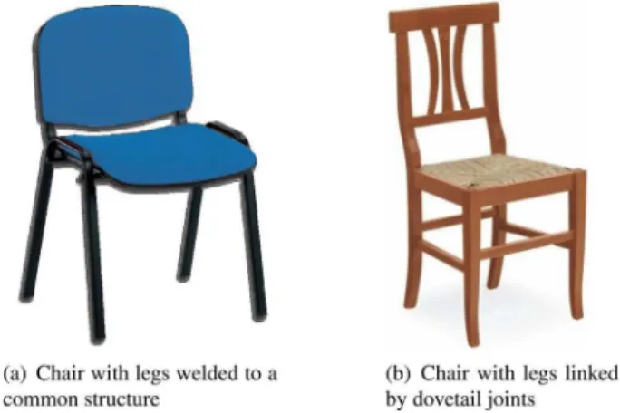
et al. [32], which aims at segmenting objects by identifying the possible joints, are not adequate in the mechanical engineering field since they are simple view-based approaches that do not handle information about the technological solutions adopted for the definition of the joints. To clarify this difference, Fig. 2
shows an example of two different chairs. The legs of the chair in
Fig. 2(a)are welded together creating a support structure that is screwed with the seat; while the legs of the chair inFig. 2(b)are represented as single parts in the CAD model and they are linked by dovetail joints. In this example, a traditional segmentation process splits the objects regardless of the building technology. In other words, it considers only how an object looks like while neglecting other important information, such as the kinematic links. Finally, even if adopting a deep learning approach in the matching process seems promising when compared to traditional methods based on graph matching, the lack of proper datasets of CAD assembly models makes such implementation difficult (see Section6).
Similarly, methods for the comparison of 3D scenes, as the one proposed by Paraboschi et al. [33], are suitable to recog-nize global as well as local object similarities at the level of the shapes, but they fail to identify internal mechanisms which typically characterize certain products. Indeed, for instance, there exist a huge amount of mechanical systems made of gears, and what characterizes these products is the arrangement of the gears, which typically has an influence on their mechanical char-acteristics (e.g. different gear reduction rate and transmission yield).
64 K. Lupinetti, J.-P. Pernot, M. Monti et al. / Computer-Aided Design 113 (2019) 62–81
This paper reviews techniques addressing the evaluation of similarities between CAD assembly models, focusing on the infor-mation implicitly embedded in the CAD models. The contribution is threefold: (i) definition of a set of criteria for the compar-ison and categorization of the existing CAD assembly retrieval techniques; (ii) an in-depth analysis and a systematic character-ization of the existing techniques with respect to the identified criteria; (iii) an exploration of the current issues and future chal-lenges. The paper is organized as follows. Section2provides an overview of the content of CAD assembly models introducing the adopted terminology and highlighting the issues character-izing CAD assembly model representations. Section3 describes how the application context may influence the similarity evalua-tion. The criteria adopted for the analysis of the retrieval methods are introduced in Section 4, while Section 5 contains the sys-tematic analysis of the assembly retrieval techniques. Finally, Section6discusses the current limitations and future challenges regarding the retrieval of content-based CAD assembly models.
2. Background: elements of a DMU relevant for assembly re-trieval
DMU represents a clearly defined set of data in the product model, whereas the term ‘‘product model’’ includes all of the information gathered during the PDP [34]. Generally, a DMU consists of three types of data [35]: geometric data (i.e. geometric description of the parts involved in an assembly model), product
structure (i.e. how the parts are gathered together) and attributes
(i.e. metadata referred to parts or to their relationships). Despite this commonly adopted decomposition structure, several alterna-tive implementations might be adopted in existing CAD systems, thus complicating the design of efficient retrieval techniques. For instance, the positioning of the parts can be performed in dif-ferent ways, and the DMU can be more or less simplified. These aspects are discussed in the next sections.
2.1. Geometric data
Geometric data describe the shape of components (parts or subassemblies) and are generated by CAD modelers. To represent a solid object, the boundary representation (B-Rep) is the de-facto standard in commercial CAD systems. Elements used in a B-Rep are shells, faces, loops, edges and vertices, as well as the corresponding geometric information, e.g. surface types and parameters, curve equations and point coordinates. In addition, a B-Rep describes how the elements are related to each other, i.e. the topology. Moreover, the history of construction sometimes is also represented as a building tree, i.e. it stores the order of the features used to design a part. Anyhow, this tree is not unique, because parts can be built in different ways and different features can be associated with them. Depending on the steps of the PDP, the building trees may however not be available.
The geometric description of the B-Rep elements can use analytic or parametric representations. Here, particular atten-tion has to be paid to the vocabulary adopted in the litera-ture. Sometimes authors refer to CAD models even though the proposed approaches deal with meshes obtained by tessellating CAD models, which is significantly different. Similarly, some au-thors refer to assembly models even though they manipulate collections of meshes [29,30,36,37]. This state-of-the-art focuses on the methods which make use of B-Rep CAD models defined by analytic and parametric representations, being those adopted in the mechanical engineering context.
Furthermore, the geometric description of the CAD models can be defined at different levels of detail depending on the lifecycle stage and the PDP organization. For instance, in the early
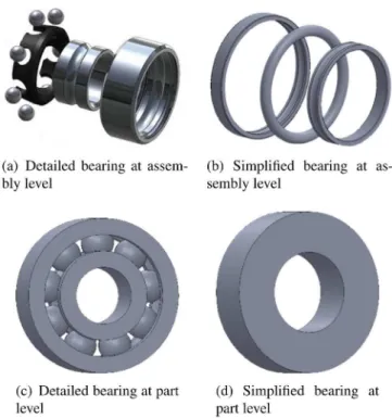
Fig. 3. Example of multiple representations and multiple resolutions related to a bearing component.
design stage, a CAD model is usually roughly detailed in all its components; later for simulation activities some components are completely detailed and others (considered less important with respect to the simulation objectives) can be simply drafted or even removed; at the final stage all the components to be man-ufactured have to be completely specified. Similarly, some parts may not be completely detailed because designed and produced by an external company. This refers to the notion of multiple resolutions of the CAD models, which has to be taken into account when developing retrieval system.
In addition, standard components (e.g. screws, nuts, bearings, gears, seals or circlips) are often imported from supplier catalogs and/or 3D databases. Therefore, they are not necessarily designed using the same CAD modeler, and also the modeling strategy may differ. Thus, for a given component, depending on the supplier, multiple geometric representations and multiple resolutions may exist.Fig. 3 shows an example where a bearing is designed in four different manners: two as assembly models and two as parts. Moreover, the representation can be complete allowing to recognize the bearing (as inFig. 3(a)andFig. 3(c)), or simplified with some idealized shapes (as in Figs. 3(b) and 3(d)) which will be hardly identified as a bearing by a traditional retrieval approach.
Finally, the possibility to represent a product in many different ways prevents the use of the number of elements of two assem-blies as an effective similarity indicator and, more generally, this large multiplicity may affect the capacity to retrieve models in a completely automatic way. Indeed, when the shape is idealized (as for the bearing inFig. 3(d)) it is hard understanding what the part corresponds to. For instance, it could represent a sim-plified bearing, a simsim-plified gear, or a simsim-plified seal. Sometimes, exploiting the information on the surrounding context of the part can help to retrieve the correct interpretation.
2.2. Product structure
Designing an assembly model is a complex process aiming at creating a product satisfying predefined requirements by a
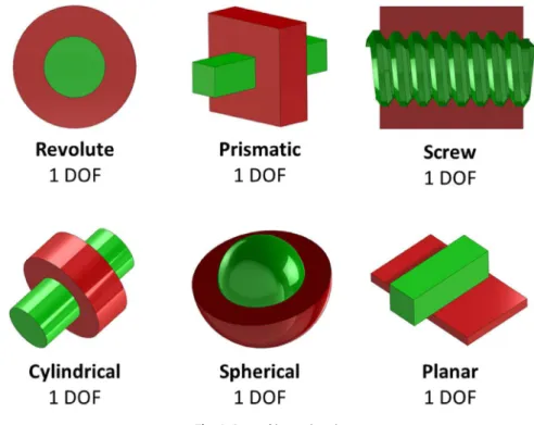
Fig. 4. Lower kinematic pairs. combination of components accomplishing specific functions. The
components of an assembly model may be gathered together using a hierarchical and logical structure of dependence among the designed parts. Such product structuring is not unique and is used to organize product data in a manner appropriate to the designers’ needs.
The most commonly adopted product structures are the as-designed (i.e. aggregating parts by their function, such that each subassembly represents a unit that performs a specific function) or as-planned (i.e. reflecting how parts have to be manufactured or assembled from a manufacturing or a process planning per-spective) structures [38]. Depending on the companies and stages of the PDP, other structures can be adopted, such as maintenance or quality structures. Sometimes, parts can be organized with re-spect to their relative positioning for visualization purposes. They can also be grouped according to their material to speed up the preparation of advanced simulations.
Finally, the product structure is usually stored separately from the geometry, even if modern CAD systems allow including it in the CAD models. When, the product structure is not available, all the parts are gathered together under a unique root node. Un-fortunately, this variability in the way assembly models can be decomposed and structured is not always taken into account by the methods in literature.
2.3. Attributes
Besides component geometry and product structure, annota-tions are used to express explicitly some geometric properties such as major/minor diameters, pitch, or number of threads [39]. Since a DMU can be simplified and details may not be fully defined, additional attributes can be used to further characterize parts. For instance, component material, and physical properties are represented as annotations. They are necessary to enable the manufacturing of a product [40] or to perform simulations. In the end, other attributes are used to identify name, number and version of a product, to distinguish its status and maturity level in the PDP and to provide details about description, material and product manufacturing information.
The above mentioned explicit information may be present in the DMU as attributes, but it is not mandatory. Moreover, the absence of conventions among designers and the variability against the industrial context make challenging to exploit this in-formation in retrieval systems. Actually, this type of inin-formation is not robust and of little use for CAD retrieval [7]. Thus, in this review, the retrieval techniques which try to make use of such unreliable information have been identified.
2.4. Components’ positioning
In addition to the definition of the product structure, design-ing an assembly model requires localizdesign-ing each part in the 3D space [41]. When considering physical objects, components are positioned relatively to the others by means of contacts. Similarly, in the DMU, parts are positioned to characterize the possible rel-ative displacements. However, this information can be not always available or designers can simply use homogeneous transforma-tions to position parts. In addition, as discussed in Section2.1, the DMU does not always perfectly represent the real configurations and some shapes may be simplified. Hence, the pure geometric information stored in the DMU to assess the contacts between two components can be ambiguous. To circumvent this limita-tion, designers often make use of extra-information to explicitly encode and constrain the relative positions of the parts. The specification of the contacts is then performed through at least one of the following solutions [39]:
•
Kinematic links (or joints)characterize the relationshipsbetween parts. They determine the positions of the compo-nents as well as the allowable movements, i.e. the allowed degrees of freedom (DOF). The kinematic links are divided into two groups: lower kinematic pairs and upper kine-matic pairs. A kinekine-matic pair is said to be a lower pair if the involved parts have surface area contact between them. Different lower kinematic pairs can be identified ac-cording to the types of surfaces involved in the contact. The possible lower kinematic pairs are depicted inFig. 4. Inter-estingly, these kinematic pairs are not necessarily linked to the shapes of the involved surfaces, e.g. the kinematic pair
66 K. Lupinetti, J.-P. Pernot, M. Monti et al. / Computer-Aided Design 113 (2019) 62–81
Fig. 5. Example of geometric constraints.
Fig. 6. Possibles interfaces between parts of an assembly model.
of two cylindrical surfaces can be a screw even though the threads have not been modeled geometrically on both parts. An upper kinematic pair arises when two surfaces are con-strained to remain in contact along a common line or at a common point [42]. Ball bearings have this type of kinematic pair, as the contacts between the balls and the inner and outer rings are punctual.
•
Assembly constraints determine the relative position ofgeometric entities (i.e. faces, edges or vertices) of parts of an assembly model. Typically, geometric constraints between parts include: parallel, perpendicular, coincident, tangent, concentric, distance and angle (Fig. 5). Kinematic pairs can be defined through a bundle of assembly constraints, but assembly constraints can also be used alone, without any definition of kinematic pairs.
•
Absolute positionswhen parts are placed in a single 3Dref-erence frame using homogeneous transformations to define the affine transformation matrix for each object.
Today’s CAD systems provide capabilities to easily specify and store the positions as well as the possible relationships between parts. However, when considering large DMUs made of several hundreds of parts, storing, updating and modifying those relationships can rapidly become very difficult, even im-possible. Thus, the parts in a DMU are often simply gathered in hierarchies of subassemblies and only the absolute positions are stored, i.e. without information about what parts are connected and how. In this literature review, particular attention is paid to the retrieval methods that assume the availability of this information.
2.5. Interfaces modeling
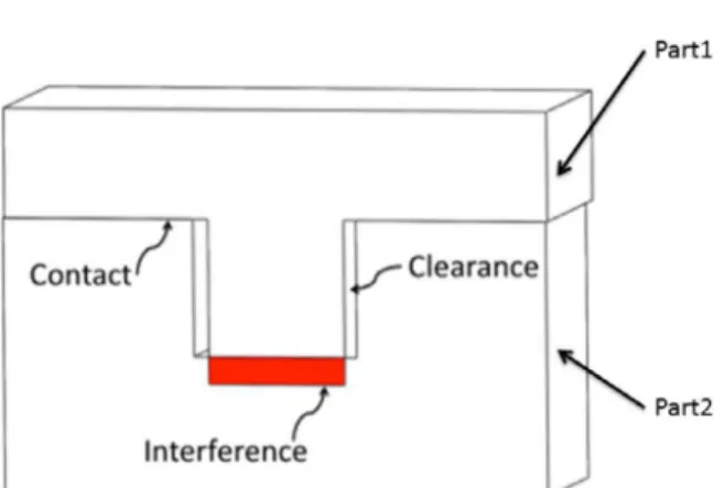
Unrealistic or unrealizable configurations may be present in an assembly model [39]. This is the case, for instance, of volumetric interferences (i.e. self-intersections) between parts of an assem-bly model [43,44]. In an assembly, interfaces may be grouped into interferences, contacts and clearances as shown inFig. 6.
In real-life situations, some of these configurations are not possible. In the DMU, they are generated by some mistakes or de-signed on purpose to convey a certain meaning [35]. An interfer-ence is a non-realistic configuration since it implies overlapping
volumes of two components in a product, which is not possi-ble for physical objects. Nevertheless, unrealistic interferences may be created on purposes, such as the intersections among screw and nut threads, or when considering flexible parts, like springs, seals and insulating parts, or when designing parts as-sembled by shrink-fitting. Thus, some of these configurations can be interpreted as imprecise positioning, while others are deliber-ate artifacts reflecting some conventional meanings [39]. Clearly, the existence of such ambiguous configurations may affect the similarity evaluation process, and two models, corresponding to similar physical objects, may be recognized as dissimilar simply because they are modeled differently. Thus, in this state-of-the-art, it is important to distinguish the retrieval methods which are able to deal, or not, with these unrealistic configurations.
2.6. Conclusions
As discussed in the previous sections, even though engineers can spend a lot of time designing and enriching industrial DMUs, there often exists a gap between the generated assembly mod-els and the corresponding real-life physical products. Unrealistic interfaces, simplified shapes, ambiguous configurations, missing information, large variability in the way CAD models can be designed and assembled, inconsistency and unreliability of the available datasets are issues that can affect the effectiveness of a retrieval system. Vilmart et al. also reached the same conclusion and emphasized the importance to have an assembly descrip-tion that is independent of any user intervendescrip-tion [45]. To this aim, the intrinsic properties of an assembly model (e.g. parts occurrences, symmetries, patterns, mating information) should be used to characterize the description of CAD assembly models. In the sight of these considerations, this review notably aims to understand how the existing retrieval approaches describe an assembly model and if the used information is provided manually by the user, or if it is automatically extracted.
3. Application scenarios and similarity criteria
Assembly retrieval may be of interest in several activities of the PDP where the criteria for evaluating similarities may obviously change according to the objective. To underline the im-portance of evaluating assembly similarity according to different points of view, this section provides an overview of some appli-cation scenarios that can benefit from assembly model retrieval, highlighting for each of them the most appropriate type of sim-ilarity and the criteria according to which it may be meaningful for the user to evaluate similarity [46,47].
3.1. 3D model reuse
In the design of new products, it is common practice to reuse existing 3D models to include components previously designed using them as originally designed, or making slight changes to meet new requirements [47–49]. To avoid starting the detailed design phase from scratch and to capitalize on previous knowl-edge, engineers might be interested in examining any existing solution considered similar to their needs. These solutions can include also components provided by third parties thus not fully
detailed. To this end, it may be useful to start a rough design of the new component and use it to search the similar components over the whole dataset. This recovery process should identify a restricted collection of assemblies that contain parts with similar shapes and comparable assembly conditions. In this case, it is use-ful to start with a rough query, i.e. a query in which the shape of the components is not fully detailed but just sketched. Thus, the similarity of the part shape must be evaluated at a level of detail that does not consider, for example, minor characteristics such as fillets and chamfers. Here, the retrieved objects may be similar to the query either partially, locally or globally. Sometimes, it may be useful to reuse and update previous designs when it is necessary to replace a certain type of product components. For example, when due to the working conditions, a type of bear-ing adopted in an assembly model needs to be replaced with another type capable of supporting more load. Retrieving all the models containing that specific component assembled in similar conditions allows identifying the products, which may benefit of the component substitution. In addition, the identification of the position of these defective components in an assembly helps to evaluate procedures and costs necessary for their replacement and to correctly update the related CAD models. Here, the type of interesting similarity is partial or local and the criteria for evaluating the similarity can be stricter, involving, for instance, also the dimensions of the components and the number of con-stituent parts together with all the information on shape and mutual relationships.
3.2. Product information reuse
This application scenario corresponds to the process of mining a database to retrieve design information and documentation associated with a given product. Generally, it allows obtaining useful knowledge for the design of a new product: technical information, production processes and costs associated with sim-ilar products previously developed [50]. For instance, if a de-signer wants to retrieve assembly instructions of some products, it might be useful to retrieve models considered either globally, partially or locally similar according to the mating conditions between components.
3.3. Product standardization and rationalization
Standardization is the process of defining common character-istics among a set of components so that they are compatible with each other. This process allows the rationalization of products by eliminating very similar components or by outsourcing products and product variations, thus reducing the size of the product portfolio to be developed.
These practices allow a considerable time saving, especially in case of complex devices with many parts which may require a complex design and/or production process. Here, the evaluation of the similarity is mainly local and can involve the functionality of a component as well as some information on how it is linked to other components. For instance, if a company aims to standardize the steering wheel of certain cars, then the specific shape of the steering wheel is not relevant, while the most important characteristic is how the wheel is linked to the drive shaft by means of external mating surfaces.
3.4. Maintenance planning
Maintenance refers to those activities necessary to preserve the status of a product preventing its damage due to the aging and deterioration of components. To this aim, the retrieval of similar assemblies meant as the identification of similar components in
a set of assembly models, and the knowledge of their rate of wear and tear helps to optimize the management of the stocks in the warehouse. Also in this scenario, the user aims to retrieve a specific component included in a set of assembly models (thus locally or partially similar assemblies with strict similarity criteria involving shape and mutual relations).
3.5. Reverse engineering
In mechanical-field, reverse engineering is the process that creates a 3D digital model starting from a physical object. The reconstruction of a digital model starts capturing data from real objects, where the acquisition may be done through different devices, as a camera, a laser scanner or a 3D computed tomog-raphy (CT). Based on the generated point clouds, designers often have to follow a tedious and time-consuming patch-by-patch reconstruction strategy to come up with a fully reverse engi-neered B-Rep CAD model. This is even truer when considering the reverse engineering of CAD assembly models. Thus, being able to shift from a patch-by-patch to a part-by-part modeling strategy can drastically speed up the CAD assembly reconstruc-tion process. Here, the ability to retrieve models into a database can facilitate some reconstruction operations, and in this case, the type of query may rely on the adopted acquisition tool. If a laser scanner has been used, then the aim is to retrieve models with a similar outer shape, while a 3D CT allows the possibility to investigate also the similarity between part relationships. In this scenario, all the three types of similarity may be interesting.
4. Adopted criteria to review the literature
In this section, criteria to analyze the existing methods that address the identification of similarities among assembly models are identified and described. The presented criteria are grouped into the following five macro-categories: objective, assembly characterization, assembly descriptor, query specification and type of similarity. Those categories are used to set upTable 1, which gathers together the synthetic evaluation of the reviewed methods with respect to the considered comparison criteria.
4.1. Objective
The process of retrieving assembly models benefits various stages of the PDP, where a different retrieval purpose may iden-tify different similarity requests. For this reason, this criterion is used to highlight the specific objectives addressed by the different methods.
4.2. Assembly characterization
To understand according to which criteria the similarity can be assessed by the works present in the current state-of-the-art, it is important to know the type of information used to describe the assembly models in the retrieval system. Thus, the set of criteria used for the characterization of the assembly refers both to the type of data and to the knowledge that the authors use to typify the assembly model and the way the information is obtained. More precisely, it includes the so-called Part
informa-tioncriterion which expresses the geometric characteristics used to describe the assembly models components, the Topological
information criterion which captures the type of information
used to characterize the relationships between the parts, the
Annotationscriterion which states if the retrieval methods make
use of such extrinsic information, and the Functional
classifi-cationcriterion to explain if the assembly descriptor elaborates
somehow these data to get a functional classification of the components.
68 K. Lupinetti, J.-P. Pernot, M. Monti et al. / Computer-Aided Design 113 (2019) 62–8 1 Table 1
Summary of the assembly retrieval methods.
Article Objective Assembly characterization Assembly descriptor Query
specification Type of similarity Part information Topological information Level of components Level of descriptor
Title Description Geometric
information Shape descriptors Statistical information Structure Kinematic link Geometric constraints Part arrangement Annotations Functional classification
Assembly Part Global Local Scale
sensitivity
Type
of
query
model
Completeness Global Partial Local
Renu et al. [51] Search for models with similar shapes for assembly instructions reuse
– SD – – – – – – – – ✓ ✓ - ✓ Part ✓ – –
Katayama et al. [52,53] Search for models with similar shapes, same number of components and same layout
– 2DP – – – – – – – ✓ – ✓ – ✓ Assembly ✓ – –
Wang et al. [54] Search for assembly models with similar shapes
– SD – – – – – – – – ✓ – ✓ – Assembly G# ✓ ✓ –
Zhang et al. [55] Search for assembly models with similar shapes
– SD – – – – – – – – ✓ – ✓ – Assembly G# ✓ ✓ –
Hu et al. [56] Search for assembly models with similar shapes and composition
– LFD PS – – – – – – – ✓ ✓ – ✓ List of parts G# ✓ ✓ –
Tao et al. [57] Search for assembly models with similar shapes and component connections for assembly plans generation
SI – EN, LN – A – – ✓ – ✓ ✓ ✓ ✓ ✓ Assembly ✓ – –
Miura et al. [58] Search for assembly models with similar shapes and component connections
– AD – – - A – – – ✓ ✓ ✓ ✓ ✓ Assembly ✓ – –
Han et al. [59] Search for assembly models with similar parts, constraints and function information
– – – – PC PC – ✓ AR ✓ ✓ ✓ ✓ – Text G# ✓ ✓ –
Li et al. [60] Search for similar assembly models of injection mold design of automotive interiors
– SD – A A – – ✓ AI ✓ ✓ ✓ ✓ ✓ Part or Assembly ✓ ✓ –
Deshmukh et al. [47,61,62] Search for similar assembly models according to multiple assembly characteristics
C,SI – – – A A – ✓ US ✓ ✓ ✓ ✓ ✓ Matinggraph G# ✓ ✓ –
Chen et al. [48] Search for similar assembly models according to multiple assembly characteristics
– SD – A PC PC C – US ✓ ✓ ✓ ✓ ✓ Assembly G# ✓ ✓ –
Zhang et al. [63] Search for similar assembly models according to multiple assembly characteristics
C,DA,SI – – A A – – – – ✓ ✓ ✓ ✓ – Assemblyset ✓ ✓ ✓
Wang et al. [64] Search for similar assembly models according to multiple assembly characteristics
– SD – – A – – – – ✓ ✓ – ✓ ✓ Assemblyset ✓ ✓ ✓
Lupinetti et al. [65] Search for similar assembly models according to multiple assembly characteristics
– 3DSH – A C – C – AI ✓ ✓ ✓ ✓ ✓ Assembly orGraph G#
G #
4.2.1. Part information
This criterion indicates which information is used to ch-faracterize the parts in an assembly model. To guarantee a comprehensive and structured classification, it is divided into: (1) Geometric information, (2) Shape descriptors, (3) Statistical information. Then, for each category only the information used by the reviewed retrieval methods are shortlisted and explained.
Geometric information
Geometric information specifies if an approach characterizes the parts of the assembly models by using data that can be easily computed processing their B-Rep models. The types of geometric information used by the methods included in this survey are described below:
•
Curvature (C): The normal curvature at a point P on asur-face varies around the normal direction of the sursur-face. The maximum and the minimum values of the normal curvature are named as principal curvatures and the difference of their signs can characterize the point on a surface. In this state-of-the-art, the works, which use normal curvature to characterize the shape of the parts, sample points on the faces and then evaluate the average of the different types of point.
•
Dihedral angle (DA): A dihedral angle is the internal angledefined by two adjacent faces on an edge. According to the normals of the faces and the direction of the edge, a dihedral angle can be concave, convex or smooth.
•
Surface information (SI): It refers to the type of surfaceun-derlying the faces of the parts, i.e. if a face is planar, cylin-drical, conical, spherical, toroidal or other; and the surface
convexity, i.e. convex, concave or planar.
When analyzing the reviewed approaches, the type of geomet-ric information used is described. Methods that exploit multiple types of geometric information report multiple labels inTable 1
under the column geometric information.
Shape descriptors
The shape descriptors indicate how the methods character-ize the shape of the parts. Shape descriptors may be computed directly from the B-Rep of the parts or they can require a pre-process to obtain a polygonal representation. This survey focuses on the type of descriptor used and not on how it has been computed. Then, for each analyzed method, only the character-istics of the adopted shape descriptors are described. The shape descriptors used by the analyzed methods are described below:
•
Shape distribution (SD): This descriptor is used to evaluatethe shape similarity of two parts. It is described by Osada et al. [10], where the 3D shape of each part is characterized by the distances of randomly sampled points on the surface of the parts. Several distances can be used to compute the shape distribution and most of the time, in the considered methods, the Euclidean distance is employed.
•
Set of 2D projections (2DP): It is a view-based descriptor tocharacterize components of assembly models according to their shape regardless of their structure. Since view-based methods are not robust to translation and rotation in the space, a set of projections is collected.
•
Light Field Descriptor (LFD): It is a view-based descriptor thatcollects different 2D views of a 3D model [66]. It is based on the idea that if two 3D models are similar, they also look similar from any view angle.
•
Angle distance (AD): The angle distance is a two-dimensionaldistribution proposed by Ohbuchi et al. [67] for the shape retrieval of components, where the first dimension indicates
the normalized distribution of distances between sampled points on a part, while the second dimension refers to the normalized distribution of inner products between the surface normal vectors.
•
Spherical harmonics (3DSH): The evaluation of shapesimi-larities can rely on the computation of spherical functions following the method proposed by Kazhdan et al. [68]. Here, a function (that represents an approximation of the object to be described) is decomposed into harmonics, the harmonics are then summed with respect to their frequency and the norm of each frequency component is finally computed. It results in a normalized histogram, which reports the values of the sums of the harmonics for the given frequencies. In particular, in their work, there are 544 bins in the histogram.
Statistical information
Statistical information indicates which numerical data are used to describe the parts of an assembly. Innumerable data can be used for this purpose, and the statistics used in the analyzed methods are listed below:
•
Part statistics (PS): Two assembly models can be comparedaccording to the parts that compose them. The works that adopt this description refer to the number of parts and how many times each part appears in an assembly model.
•
Edge number (EN): This criterion indicates if the methodstake into account the number of edges or of outer edges to characterize the parts of an assembly model.
•
Loop number (LN): This criterion indicates if the methodsmake use of the number of loops to characterize the parts of an assembly model.
When analyzing the reviewed approaches, the type of statisti-cal information used is described. Methods that exploit multiple types of statistical information report multiple labels inTable 1
under the column statistical information.
4.2.2. Topological information
This criterion helps to describe the type of information used to characterize the relationships among the parts of an assembly model. Here also, a method can make use of several of those de-scriptors and this is highlighted by multiple labels in the column
topological information ofTable 1:
•
Structure: If a method makes use of this descriptor, it meansthat it exploits the hierarchical decomposition of the assem-bly models, as described in Section2.2.
•
Kinematic links: This descriptor refers to the relationshipsdefined by the contacts between parts as described in Sec-tion2.4. In the analyzed works, this information sometimes is referred as mating conditions or joints between two parts.
•
Geometric constraints: This descriptor refers to theexploita-tion of specific constraints between geometric entities of two parts of an assembly model, as described in Section2.4.
•
Part arrangement: Since different parts can be positioned inan assembly model in several ways, this descriptor charac-terizes if the analyzed works are able to recognize particular part arrangements in the 3D space, e.g. repetition of some parts.
In this paper, each method is analyzed to identify whether it uses or not (
−
) the above-mentioned topological informa-tion. Table 1also details the way the information is collected: (A) characterizes methods which assume that the relationships between the components of an assembly are explicitly encoded and available from the native CAD models; (C) indicates that they are automatically derived and computed from the assembly70 K. Lupinetti, J.-P. Pernot, M. Monti et al. / Computer-Aided Design 113 (2019) 62–81
geometry; (PC) if they are partially computed (i.e. if some con-figurations are automatically extracted and others are manually specified by the user).
4.2.3. Annotations
As described in Section 2.3, attributes are sometimes added and attached to the assembly models to specify details on the shape of the parts or to further specify useful data (e.g. mate-rial, welding types and tolerances). Here, this criterion simply captures whether the reviewed methods use (✓), or not (
−
), an-notations as structured metadata (e.g. ontology or thesaurus) or simple text annotations. As discussed earlier, exploiting such un-reliable information cannot be considered as an effective practice for retrieval applications since it is user- and system-dependent.4.2.4. Functional classification
Today, there is a growing interest in developing knowledge-based and semantic-knowledge-based assembly retrieval systems to access and to exploit the functional characteristics of the product com-ponents and subassemblies [3,45]. Functional information can be extracted automatically by reasoning on some information available in the CAD models, or exploiting support systems that encode product data, or using user-specified data. To character-ize the methods according to the techniques used to populate the functional information, this criterion can be associated with different labels: user specification (US), algorithm reasoning pro-cedures (AR), artificial intelligent techniques (AI), or use of ad-hoc tools such as PDM/PLM systems or ontologies (ST).
4.3. Assembly descriptor
This criterion aims to characterize the assembly model de-scriptor adopted by the different reviewed works. In particular, it specifies the Level of components that are described, the Level
of descriptorand if the assembly descriptor is Scale sensitive.
4.3.1. Level of components
This criterion indicates if, in the reviewed works, the assembly models are described at the level of the Assembly, at the level of the Part, or at the level of the Feature. At the assembly level, an as-sembly model is described by its parts and their relationships. At the part level, an assembly is described only through the list of its parts, and at the feature level, shape portions having specific assembly meaning are used to characterize an assembly. Since none of the analyzed methods uses the feature level description, inTable 1this level does not appear.
4.3.2. Level of descriptor
It indicates if the assembly descriptor is able to capture local characteristics of an assembly model or if it describes the assem-bly under a global point of view. Thus, this criterion may take two values: Global or Local. Note that even if the descriptor is able to characterize the assembly model at the local level, this does not automatically imply that the retrieval method exploits this ability to assess local or partial similarities.
4.3.3. Scale sensitivity
This criterion specifies if the method is able (✓), or not (
−
), to distinguish assemblies with the same number of parts and assembled in the same order, but having different sizes. Usually, this ability relies on the type of data used to characterize the assembly models. For instance, shape distribution descriptors that compute several distances on the surface of a part are influenced by the dimension of the part if these distances are not normalized.4.4. Query specification
A database can be queried in multiple ways according to both the available data and the user’s search purpose. For instance, to retrieve similar assemblies to get information about their as-sembly plan, it is reasonable to use as query a detailed asas-sembly model, so as to take into account all the related information, while, to retrieve models with similar shapes, then it is sufficient to use as query just a list of the parts involved in the assembly. For this reason, this criterion is introduced to specify the Type of
query model, i.e. how the query is expressed as well as the type
of associated input data, and the model Completeness, i.e. if all the elements of the query model are defined at the same level.
4.4.1. Type of query model
This criterion indicates the type of data used to represent the query model. According to the reviewed literature, it can assume the following values: single CAD assembly model (Assembly), set of CAD assembly models (Assembly set), CAD part model (Part), set of CAD part models (List of parts), and abstract assembly descriptor (Text, Mating graph or Graph).
4.4.2. Completeness
Some works allow leaving unspecified some elements of the query model. In this state-of-the-art, a method that requires the use of a Complete query is labeled by the symbol , while the symbolG#is used to characterize methods that can make use of
an Incomplete query model. This criterion applies to any type of query model, i.e. on both CAD assembly models and abstract representations of assembly models. Naturally, the possibility to make use of incomplete query opens more possibilities to the corresponding retrieval methods.
4.5. Type of similarity
This criterion allows the characterization of the reviewed methods according to their ability to assess Global, Partial and
Local similarities as introduced in Section 1. Clearly, the use of an assembly descriptor able to characterize a model at the local level does not imply that the retrieval method exploits this characteristic to assess a partial/local similarity. For example, this happens when the representation of an assembly model is based on graphs and when the matching method looks for graphs or subgraphs isomorphisms. Indeed, a graph-based representation is able to capture a local similarity between two assembly models, this is represented by a common subgraph between the two graphs. If the retrieval method uses graph isomorphism matching applied to the entire query and the entire target models, then the similarity is evaluated at the global level and the local simi-larity will not be captured. To capture local simisimi-larity the use of subgraph isomorphism is preferable.
5. Overview of techniques for assembly model retrieval
While the literature of shape-based retrieval of parts is very vast, the interest of the research community in the retrieval of CAD assembly models is quite recent. In this section, the principal methods for assembly model retrieval are discussed and char-acterized using the criteria introduced in Section4. In addition, when possible, the time complexity of the adopted matching algorithm is reported. Unfortunately, since only a few works provide it or detail the adopted algorithms, an exhaustive analysis on the time complexity of the studied methods is not feasible.
Methods have been grouped into two main categories distin-guishing the methods that consider only the information related to the parts constituting the assembly model (Section5.1) from
the methods that also exploit topological information among the parts (Section 5.2). Each group is further decomposed in subcategories according to their ability to address the different types of similarity introduced in Section1, i.e. Global, Partial and
Local similarities. This section ends up with a synthesis of the
survey andTable 1summarizes the assessment of each method according to the previously introduced criteria. Obviously, this survey reflects our understanding of the reviewed methods, based on a systematic analysis of the available papers published at the time of the survey.
5.1. Retrieval methods using only shape information
This section gathers together methods that address assem-bly model retrieval based solely on the shape of the constitut-ing parts. The shape description of each part can be managed individually in the assembly descriptor or processed to get a global description of the entire CAD assembly model. Methods are analyzed according to their ability to recognize only global similarity (Section5.1.1), or also partial one (Section5.1.2).
5.1.1. Global similarity
Renu and Mocko [51,69] explore the use of model similarity and text analysis approaches to develop a relationship between solid models and assembly work instructions. This is aimed at supporting the reuse of decisions taken during the assembly pro-cess design. To reach this objective, the authors have fixed three objectives: (i) evaluate solid model similarity in terms of their as-sembly processes; (ii) investigate the natural language processing approaches required to analyze assembly work instructions; (iii) use part geometry information to mine databases of assembly work instructions and retrieve relevant work instructions. In [51], the authors have faced the first objective aiming to search for
models with similar assembly instructions, thus addressing the reuse of product information. Their process to determine solid
model similarity consists of the following four steps:
•
Compute histogram-based similarity scores:In this step,Osada’s method [10] is used to generate shape descriptor for each part of the compared assembly models.
•
Generate clusters of similar solid models based onhis-togram score: The adopted shape descriptor provides
sim-ilarity of overall shape of solid models and it is used to generate clusters of similar models.
•
Compute surface area and tessellation area distributiondifferences: Here, to recognize local differences between
CAD models, like the one illustrated inFig. 7, the tessella-tions of solid models within each cluster are analyzed for evaluating the differences of the surface areas and of the area distributions.
•
Multi-index sorting to generate ranked list of similarsolid models: Finally, a multi-index sorting is performed
on the values of the difference parameters (e.g. global his-togram similarity, difference in surface area, difference in tessellation area) to rank the models recognized similar to the given query assembly model.
In this work, there is no evidence of the use of assembly relationships information (
−
). The part information uses a shape distribution (SD), which is computed from the tessellations of the parts. Since the method involves area value in the evaluation of the similarity, the method is scale sensitive (✓). Finally, this method characterizes assembly models at the level of parts and the query model has to be a complete ( ) assembly model.Katayama and Sato [52,53] developed a method for the
re-trieval of globally similar assembly models, which evaluates the
similarity according to their hierarchical decompositions. The
Fig. 7. Local differences in CAD models and their tessellations [51].
idea is to define a new representation of an assembly model, which conveys the global shape of the assembly as well as the shape of the single components.Fig. 8illustrates the main steps of their method for the similarity evaluation of two assembly models, where different components are specified using different colors. Similarly to view-based methods [8], the components of an assembly model are projected into a set of 2D planes, where the components are identified by their design name. The size of the 2D planes is proportional to the size of the CAD model, and the re-sulting projections are rotation- and translation-dependent. Then, the 2D Radon transform and the Fourier transform are applied to the results of the projections. The distance between each pair of components is then computed using the Euclidean distance. The final distance of two assembly models is given by the sum of the distances between the corresponding components.
This method characterizes assembly models according to their shape and indirectly to their structure. Indeed, the structure is not considered as a proper topological relation, but it is used to define the way components are projected. For this reason, this method has been included among the works that do not make use of topological information. Anyhow, the fact that the structure is considered means that the adopted assembly descriptor charac-terizes the models at the assembly level. Parts are characterized by a set of 2D projections (2DP) and the method is scale sensi-tive (✓). Finally, the input for this retrieval method is an assembly
model and the number of components has a strong impact on the similarity assessment, since two assembly models having different numbers of components are not considered similar ( ).
5.1.2. Partial similarity
To retrieve assembly models, Wang et al. [54] compare the shapes of all the constituting parts. The query is represented by an assembly model but, since only its parts are considered, the query model can be incomplete (G#).
In their approach, an assembly model is described as a point set, and the comparison of assembly models is transformed into the comparison of point sets (Fig. 9). The point set is obtained by taking the heights of the bins in the histograms encoding the shape distribution descriptors of the parts of the assembly. In this way, the assembly descriptor is characterized at the part level. Since the same set of parts may originate different as-semblies, whose differences cannot be captured, the descriptor characterizes the models at the local level. For the matching of point sets, the Earth Mover’s Distance (EMD) strategy pro-posed by Rubner et al. [70] for image retrieval is used. Here,
72 K. Lupinetti, J.-P. Pernot, M. Monti et al. / Computer-Aided Design 113 (2019) 62–81
Fig. 8. Example of the procedure to compute the distance in terms of shape and structure between two assembly models [53].
Fig. 9. Example of the description of an assembly model [54]. the complexity of the method depends on the algorithm used to
compute the EMD between two n-bin histograms, which usually is O(n3log n). Anyhow, they do not provide any further details on
the adopted algorithm.
Lately, Zhang et al. [55] adopted a modified Hausdorff distance on the same assembly descriptor. This modified version, proposed by Dubuisson and Jain [71], takes the mean distance between two point sets. In [71], the time complexity is not discussed.
Also in this case, incomplete query models are allowed (G#).
In-deed, since the relationships between parts are not considered, the query model can simply be a set of parts which have to be present in the target model. Then, the matching techniques allow retrieving both Global and Partial similarities. Finally, these techniques suffer from several limitations: (i) the description power of the shape distribution, i.e. complex shapes cannot be
disambiguated, (ii) the computational time to perform a many-to-many matching in case of complex assemblies and, above all, (iii) the non-consideration of the relationships between assembly components.
Hu et al. [56] provide two methods for the matching of as-semblies exploiting only geometric information of the parts. The first method is based on vector space model (VSM) for the exact matching. In this approach, the generic j-th assembly of their database is represented through a n-dimensional vector dj
=
(
w
1j, . . . , w
ij, . . . , w
nj), where n is the number of parts in the j-th assembly andw
ij is the weight of the i-th part in the j-thassembly. The weights are computed taking into account two factors. The first relevant factor considers the number of occur-rences of a part and the assembly complexity, i.e. the number of composing parts. The second one regards the uniqueness of a part. Indeed, a part that occurs in few assemblies is more
discriminating for matching operations. Assembly statistics (PS) are computed by analyzing the assembly and identical parts are recognized by using Light Field Descriptor (LFD) [66]. Using this vector space model (VSM), the assembly descriptor is able to capture local characteristics of the model but not its global shape (or other global features).
The similarity between two assemblies is computed as a func-tion of the angle between their associate VSMs. This approach provides only exact matching, which is too limited in real applica-tions. To overcome this limit, the authors propose also a relaxed matching algorithm. Consequently, the query can be seen as an incomplete assembly model (G#), since it is possible to select an
assembly model or just a set of parts that has to be included in an existing model. This matching problem is solved using the graph theory, in particular employing a bipartite graph. The parts of the query and of the target assemblies originate the graph nodes, while the graph arcs represent the similarity between two parts. The bipartite graph matching problem is solved using the Kuhn–Munkres algorithm [72,73] allowing to detect both the Global and Partial similarities. However, this technique is computationally expensive, O(n3), thus the authors propose an
approximate matching algorithm. With their greedy approach, the
matching process complexity is reduced to O(n).
The main limitation of the method of Hu et al. relates to the assumption that two assembly models are similar if they mostly share the same parts. This can be a filter to reduce the number of models to be compared, but it cannot distinguish assemblies constituted by the same parts differently assembled.
As a conclusion, in this section, the approaches are strongly based on the shape information and do not use assembly rela-tionships, i.e. no topological information is used. Thus, geometric constraints, kinematic links, or part arrangements are not ex-ploited, which may restrict the application scenarios for which the reviewed assembly retrieval system can be applied. Also, the parts’ position is not considered by almost all these works, indeed [51,54,55] and [56] combine only data on the shape of the assembly parts without examining their absolute position. Con-versely, Katayama and Sato [52,53] take into account the parts’ position in an indirect way. Indeed, they do not reason on the transformation matrices of the parts, but they compute the shape descriptor of assemblies directly on the models resulting from the final assembly process, i.e. considering the parts in their absolute position.
Lastly, the methods using assembly descriptors able to char-acterize assembly models at local level fail to identify local sim-ilarity because of the adopted matching techniques. Effectively, there is no evidence that the query model may be bigger than the retrieved correspondences, then they require that the query model is included in the target model at least. Theoretically, by revising the matching procedure, these methods can detect also local similarities.
5.2. Retrieval methods using shape and topology information
This section presents retrieval methods that make use of as-sembly relationship information. The relationships in asas-sembly models may be represented by the use of graph-based descrip-tors. Even if different graph structures can be adopted, individual assembly components are usually represented as nodes, links between components as arcs of the graph and other information are represented in form of attributes of nodes and arcs. Here again, methods are categorized and analyzed according to their ability to recognize global, partial and local similarity and finally those that assess all the three different types of similarity.
5.2.1. Global similarity
Tao and Huang [57] propose an approach to find assem-bly models for design reuse and generation of manufacturing plans. Their component attributed relational graph (CARG) rep-resents an assembly model as a direct graph where the nodes represent the components and the arcs correspond to connec-tions between two components. Several attributes are associated with the nodes and the arcs for the description of the assembly model. In particular, each node encodes the component volume, the surface type (SI), the surface convexity (SI), the loop number of a face (LN) and the edge number of its outer loop (EN). An arc represents the adjacency relationship between two compo-nents and encodes the types of contact surface pair and the connection relations, which can assume the following values: screw connection, pin joint, key joint, rivet joint, bearing, belt, chain and bonding or welding. Since the description of the single parts has been preserved in each single node, and has not been collapsed into a unique assembly descriptor, this descriptor is able to capture both the entire assembly as well as the details at the level of its parts.
Using a graph as assembly descriptor, in principle, local simi-larity could be detected. However, the adopted matching proce-dure is based on a global evaluation of the similarity. It computes the similarity S(P1
,
P2) between two components P1and P2 con-sidering the stored properties and the connection relations. To evaluate the similarity between two assemblies A1 and A2, acompatibility matrix SM(A1
,
A2) is built, where the element in the i-th row and j-th column is S(P1i
,
Pj2). Then the similarity betweenthe assemblies A1and A2is computed as follows: S(A1
,
A2)=
SM(A1,
A2)max max (m,
n),
(1) where SM(A1,
A2)max is the value of the optimal matchingcom-patibility matrix SM(A1
,
A2) evaluated using Kuhn–Munkresal-gorithm [72,73] and m (resp. n) is the number of components in
A1(resp. A2). The authors do not discuss the complexity of their
method, anyhow the Kuhn–Munkres algorithm usually has o(k3)
time complexity [74], where, in this case, k
=
max(n,
m). This method uses simple geometric information and kinematic links to characterize parts of assembly models and their rela-tionships. The geometric information is partially directly avail-able from the B-Rep model of each part (A), and Kinematic links are available likewise (A). The use of surface area makes the method sensible to dimension differences, i.e. it is scale sen-sitivity (✓). The values as ‘‘rivet joint’’, ‘‘bearing’’ and so on, used to characterize the connection relations, suggest that some attributes (✓) are supposed to be available in CAD models.Miura and Kanai [58] provide a 3D shape retrieval method which satisfies the following four requirements: (i) evaluating as-sembly structure similarity (i.e. the method evaluates shape and structure similarities of the assembly); (ii) maximum matching ability (i.e. similarity measure should not change significantly if a minor component changes in the assembly); (iii) insensitivity to the movable components (i.e. similarity measure should not consider relative positions of the components in an assembly model); (iv) flexible control of similarity evaluation (i.e. similarity should be easily defined and tuned by the designer).
The adopted assembly descriptor is an assembly graph, where each node corresponds to a component in the assembly and each arc indicates a contact, an interference or if at least a geometric constraint is present between two components. To characterize the geometry of the model, several attributes are specified for nodes and arcs. In particular, the area, the volume and the angle distance (AD) are associated with nodes, while the type of constraints characterizes the arcs (if they identify a
![Fig. 7. Local differences in CAD models and their tessellations [51].](https://thumb-eu.123doks.com/thumbv2/123doknet/7403825.217641/11.892.478.832.80.348/fig-local-differences-cad-models-tessellations.webp)
![Fig. 8. Example of the procedure to compute the distance in terms of shape and structure between two assembly models [53].](https://thumb-eu.123doks.com/thumbv2/123doknet/7403825.217641/12.892.127.755.78.365/example-procedure-compute-distance-terms-structure-assembly-models.webp)
![Fig. 10. Example of a CAD model and a part of its EAM descriptor [65].](https://thumb-eu.123doks.com/thumbv2/123doknet/7403825.217641/17.892.225.694.79.452/fig-example-cad-model-eam-descriptor.webp)
