Science Arts & Métiers (SAM)
is an open access repository that collects the work of Arts et Métiers Institute of Technology researchers and makes it freely available over the web where possible.
This is an author-deposited version published in: https://sam.ensam.eu Handle ID: .http://hdl.handle.net/10985/19275
To cite this version :
Tristan BRIARD, Frédéric SEGONDS, Nicolo ZAMARIOLA - G-DfAM: a methodological proposal of generative design for additive manufacturing in the automotive industry - International Journal on Interactive Design and Manufacturing - Vol. 14, n°3, p.875-886 - 2020
Any correspondence concerning this service should be sent to the repository Administrator : archiveouverte@ensam.eu
G‑DfAM: a methodological proposal of generative design for additive
manufacturing in the automotive industry
Tristan Briard1,2 · Frédéric Segonds1 · Nicolo Zamariola2
Abstract
Metal additive manufacturing is an emerging technology in the industry and has a great potential. Moreover, new technolo-gies like generative design can maximize this potential by computing complex optimized parts for additive manufacturing solutions. However, there is a lack of methodologies combining both recent and promising technologies. This paper first establishes a state of the art of design for additive manufacturing (DfAM) and generative design methodologies. Then it proposes a generic workflow for generative design tools and it proposes a challenge approach to develop a new DfAM method including generative design tools. Finally, a global 4-step methodology maximizing the potential of generative design and additive manufacturing, the G-DfAM method, is presented and validated through an automotive use case.
Keywords Generative design · Additive manufacturing · Design methodology · Design for additive manufacturing
1 Introduction
Additive Manufacturing (AM) is an emerging production technology in the industry often seen as the next industrial revolution. Indeed, AM is growing bigger every year and forecasts on the related market see this trend growing even more, as the use of this technology keeps increasing and the fields of application are expanding [1]. In comparison to conventional manufacturing technologies, AM tends to offer a higher freedom of design and possibilities for mass customization [2]. Moreover, this flexible technology can produce prototype as well as finished part in a short matter of time without tooling or moulds [3]. It can also manufac-ture complex parts for both professional and personal uses. Furthermore, emerging Computer-Aided Design (CAD) technologies like generative design can maximize the already huge potential of AM. The generative design tools propose optimized parts or assembly by using computer power and optimization technologies [4]. In the same way as the AM field, the generative design ecosystem keeps
growing every year. There is an increasing use of generative design solutions in major industries like the automotive and aerospace domains, as well as a growing number of genera-tive design tools [1]. Major CAD actors have also developed their own generative design solution to follow this trend.
The interactive design appeared to join different engineer-ing cultures [5]. The number of different disciplines involved in the design process related to AM process makes it neces-sary to adapt an interactive approach i.e. an approach that facilitates the integration of new disciplines using expert tools in a global methodology.
Considering the novelty of both AM and generative design technologies, there is currently a lack of methodol-ogy combining it together. Thus, this paper intends to answer the following Research Question (RQ): how to include Gen-erative Design in the Design for Additive Manufacturing (DfAM)? To do so, a new design methodology using gen-erative design tools to design additive manufactured parts, the G-DfAM method is proposed. First, a review of DfAM methods and a review of generative design are presented. A generative design workflow is then proposed, as well as the experimentation led to develop the new method and its results. At last, conclusion on the research and future works are proposed.
* Frédéric Segonds
frederic.segonds@ensam.eu
1 Arts et Métiers Institute of Technology, LCPI, HESAM
Université, 75013 Paris, France
2 ArcelorMittal, Global Research & Development,
2 State of the art
2.1 Design for additive manufacturing 2.1.1 Dual DfAM approach
To face the highly competitive marketplaces and their increasing needs in terms of production costs, quality and time to market, different new design methodologies emerged and, among them, the Design for X (DfX) [6]. The X rep-resents a particular perspective to improve during the prod-uct design as well as the design process [7]. This method considers all the product lifecycle during the early stage of design to improve its competitiveness [8]. To do so, DfX “is intended to explicit all the required knowledge of the product, process, and material in the early design” [9]. DfX applied to the AM process is named DfAM. It aims at using the full potential of the AM technologies for design. DfAM is also a set of tools dedicated to AM design methods. Three different methodological approaches are usually cited [9]: the opportunistic approach, the restrictive approach and the dual approach. The opportunistic approach, as the name sug-gests, tends to put no limit on the complexity of AM. The restrictive approach tends to consider the limits of AM in terms of materials, performance and characteristic of the AM machines and the manufacturability. The last one, the dual approach is the combination of both the opportunistic and restrictive approaches. The dual approach DfAM meth-ods have been reviewed and resumed in two main methmeth-ods:
the Component DfAM and the Assembly DfAM presented on Fig. 1 [9].
2.1.2 Component DfAM (C‑DfAM)
The C-DfAM method is the component-based method. It aims to design or redesign a single component or part. In the first step of this method, the designer can either define the functional entities for a topology optimization or take the initial CAD model of the part to blend in parametric lattice structure. Regardless of the early steps’ choice, the last steps are the same, the designer then needs to adapt the shapes of the optimized part to fit the manufacturing strategy [9]. Finally, a last assessment of the part is made to integrate “post-processing tasks (removal of supports, polishing), and the estimation of the manufacturing costs” [10].
2.1.3 Assembly DfAM (A‑DfAM)
The A-DfAM method is the assembly-based method. It aims to design or redesign an assembly or set of components into fewer elements. In this method, the first steps are defining the specifications of the assembly and grouping the specifi-cation functions into set. Then two different approaches are possible. On the one hand, the designer proceeds to a topol-ogy optimization of each functional set of components. On the other hand, the designer can define the geometry for each functional set and, by reusing or adapting these geometries, find one that work for all the functional sets. Either way, the
components are subjected afterward to a shape assessment like in the C-DfAM method [9].
2.1.4 Synthesis on DfAM
The new G-DfAM method proposed (answering the RQ) should consider the liberties offered by the AM process but also consider both its limitations and guidelines. So, it will be a dual-DfAM method. The proposed method will also integrate elements from existent DfAM methods and mostly from C-DfAM methods. They have to some extent a similar-ity of process with the generative design process.
2.2 Generative design
Generative Design (GD) is “a category of technologies that suggests design options, or optimizes an existing design, to meet criteria defined by the user” [4]. Indeed, designers specify their part constraints and objectives in GD software. Then the software aims to propose an optimized part design. The suggested options can be optimized for weight, stiffness, frequency, etc. [11]. In that way GD has a significant impact on the design process. Part of the design process is now
automated by GD software, saving time for designers but also changing their conventional working process. Their new role is now to make a complete prior study of the part, so they can set up every relevant input (simulation parameters, criteria and objectives) for the GD software. At the end of the GD process, it is also the designers’ role to review the different design options and choose among them the best-suited for their application [12].
2.2.1 Topology optimization
There are different tools available for GD, for example lattice infill or meta-structure blending. But the most popular tool, carrying automated optimization, is topology optimization [4]. Topology Optimization (TO) is the technology optimiz-ing the material layout within a given design space [13]. TO goals is to optimize a part property (weight, stiffness, fre-quency …) while respecting a certain set of constraints. To do so, the TO process uses various mathematical algorithms and methods. Each TO method has several versions aiming at faster optimization or addressing inherent optimization’s issues. Three different algorithms will be presented and their iterations are illustrated on Fig. 2.
Fig. 2 Topology optimization: on the left SIMP method iterations [13], on the upper right ESO method iterations [14], on the bottom right MMC method iterations [16]
One of most popular TO method is the Solid Isotropic Material with Penalization (SIMP) method. This discrete method idea is to give element a continuous virtual density between 0 and 1 and steer the result to 0 or 1 after each itera-tion with a penalizaitera-tion factor [13].
Another noteworthy discrete method is the Evolution-ary Structural Optimization (ESO) method which is based on biomimicry. This discrete method uses finite element analysis to determine and remove the inefficient elements and make the structure evolve into its optima counterpart. Indeed, after each iteration, the elements with the lowest stress density are removed until all the remaining elements have an equal stress density [14]. One direct improvement of this method, even closer to mimicking nature growth, is to also add elements near the highest stress density elements as well as removing the lowest stress density one [15].
The discrete elements methods face some issues of their own, the two most common are the mesh dependency issues, i.e. optimization results vary depending on the mesh, and the checkerboard issue, i.e. stiffness is virtually high due to a checkboard pattern of the elements. Addressing these issues, a recent TO method emerged: The Movable Morpha-ble Component (MMC) method. In opposition to the two previous methods, MMC is not discrete. The main idea is to find the optimal structure topology by optimizing the thick-ness, shape, orientation and layout of a set of morphable components, i.e. “building blocks” [16].
2.2.2 Synthesis on generative design
The study of GD is fundamental to understand the GD tools optimizing operations. It also allowed to review the various
tools possibilities, similarities and differences. Moreover, the tools study was key in the development of the proposed GD process workflow (Fig. 4). This workflow process was then integrated in the new G-DfAM method answering the RQ.
2.3 Additive manufacturing and generative design synergy
Developing a DfAM method integrating GD is important because there is a real synergy between AM and GD technol-ogies [17]. Indeed, AM is maximizing the potential of GD and vice versa. For example, most of the time, the optimized parts have an “organic” design. Thus, their shapes appear random, of variable thicknesses and are often asymmetrical, an example of different GD options is illustrated Fig. 3. They can be difficult to manufacture using other technologies than AM. Moreover, in an AM production context, every material preserved with GD optimization can be used to manufacture the next part [18]. The GD optimized parts will also be faster to manufacture improving the printing machines productiv-ity. That way, the combination of the two technologies can then lead to major material and cost savings on an industrial scale.
Furthermore, with AM, one can consolidate multiple components into only one solid part or even functional mechanical assembly [19]. Coupled with GD, the gener-ated part will fulfil the original assembly objectives and constraints, sometimes with even better performances. But most importantly, the part will also reduce production costs. Indeed, there is no more need for dedicated tooling and since fewer parts needs to be tracked and tested, production man-agement is simplified [20].
3 A generic generative design workflow
proposal
Based on the study and review of different GD tools, a generic workflow for the GD process has been proposed in the following Fig. 4.
Before starting the GD process, a preliminary study con-cerning the part context is required. This study is crucial since all the final GD options proposed in the end rely on it. Meaning, the designer needs to have a perfect understanding of all part interactions with its environment before starting the GD process.
3.1 Translation phase
The first phase in the GD process, based on the results of the previous functional analysis, is the translation. In this phase, the part specifications are “translated” in inputs for the GD software. The designer must define the foundation of his optimization: the design space. The design space is the
entire volume available in which GD software can operate, every space outside the design space cannot be used. Thus, according to its previous study of the part, the designer role is to determine the maximal space the part could fit in, so the results at the end of the process are the most optimized ones. To complete the design space, the designer also needs to specify the preserved geometries and voids within the design space, i.e. the functional volumes. Then, the designer applies the set of loads and boundary conditions, i.e. the load cases, on this design space.
3.2 Processing phase
To start the second phase, the designer needs to set-up his/ her optimization, i.e. to point out the optimization objectives and constraints. Some usual parameters are the material, the percentage of the design space volume for the solution, the minimal element size, etc. The designer can now run the optimization process.
Fig. 4 Proposition of a genera-tive design workflow
The second step of the GD process is the computing, this step usually does not involve the designer except for software proposing live feedback and live modification on the optimization runs. With all the previous step informa-tion, the software finds solutions achieving the specified objectives and constraints.
In the third step of the GD process, the designer must review the options proposed by the GD software to find the one best suited to its needs. The designer expertise is once again crucial as the choice is based on the part con-text in terms of cost, manufacturing, production, quality, etc. If the designer is not satisfied by the GD proposed options or if he wants to refine the optimization results, he can loop back to the first step to modify the optimiza-tion parameters and generate new opoptimiza-tions.
In the fourth step, the designer can refine even more the solution afterward by blending complex meta-struc-ture in the optimized part. For example, some software
proposes to blend complex meta-structures like lattices, gyroids, bone-infill like structures, etc.
Once this refinement is done, the designer should finally run an analysis of his/her solution to determine its performances and ensure the validation of the part speci-fications. If the specifications are not met, the designer should loop back to the first set-up step and modify the initial parameters.
4 A challenge approach to build a new
DfAM methodology
4.1 Preparation of the challenge
To answer the RQ and develop a new AM design method integrating GD tools a challenge approach has been developed.
Fig. 5 Seatbelt bracket part context
Fig. 6 On the left S-in-Motion Seatbelt bracket to optimize, on the right the design space proposal
4.1.1 Case study
The objective of the challenge is to optimize the seatbelt bracket of the S-in-Motion® Seat solution. This typical
auto-motive part, illustrated on Fig. 5, is perfectly suited for a GD optimization and an AM due to its small size and its simple specifications.
A mechanical study of this seatbelt bracket allowed to determine the objectives and constraints of the optimization challenge: to set up the challenge, the following design space (Fig. 6) and two main load cases were chosen. The goal is to minimize, with the help of one GD tools, the weight of the bracket while in the same time keeping maximum Von Mises stress and maximum displacement levels under the original part ones.
Two ArcelorMittal teams participated to the challenge. All the participants were specialized in the AM process and familiar with GD tools. This expertise in both fields is highly valuable for the research because it guaranties consistent results and methodology.
4.1.2 Challenge organization
The challenge was organized without influencing the partici-pants in the choice of their design methods. The concepts evaluation criteria aimed to give hints on what was expected as an optimization result.
The resulting concepts were reviewed and ranked accord-ing to the 4 followaccord-ing criteria: performance, refinement, AM readiness and creativity. Each main criterion was weighted according to its importance and subdivided in different smaller criteria for a more precise evaluation. Then, every sub-criterion was evaluated on a scale from 1 to 3 giving in the end a rating out of one hundred to each challenge solu-tion. This ranking aims to highlight the concepts maximising the potential of both AM and GD.
• The performance of the optimization, with a weight of 4, is the most important criteria. It evaluates the difference between the performances of the original part and the optimized part in terms of weight, maximal Von Mises stress and maximal displacement. This criterion encour-ages the participants to push the optimization to its lim-its, finding the best compromise between weight, stress and displacement.
• The refinement of the optimization, with a weight of 3, evaluates the use of GD potential. It considers the pres-ence of specific meta-structures like lattice, complex infills (honeycomb, gyroids, etc.) as well as the simplic-ity of shape and geometry of the proposed concept. This criterion encourages pushing the optimization’s limits even further by refining the already optimized parts for extra weight/stress reduction or stiffening.
• The AM readiness of the optimization, with a weight of 3, evaluates to what extent the AM guidelines have been integrated in the results [21]. Thus, it considers AM spe-cificities like supports optimization, continuous thickness and production optimization [22]. This criterion encour-ages the participants to keep in mind the specificities of the AM process and integrate them in their results.
• The creativity criterion, with a weight of 2, is more subjective and slightly less important than the previous criteria. It evaluates if a concept stands out for its origi-nality or aesthetic. This criterion should encourage the participants to think outside the box and return an origi-nal solution at the end of the challenge.
4.1.3 Challenge survey
Among with the CAD files and the challenge description, a specific survey addressing the participants of the challenge was also developed. The purpose of the survey is to retrieve crucial feedbacks on the methodologies of optimization used by the participants. The survey was divided in different parts and covered the entire GD process.
The first part of the survey tends to evaluate the partici-pants experience with GD as well as AM. The second part evaluates the participants’ method among with the difficul-ties encountered in the process and the solutions used to address specific aspects of the challenge. For most answers, Likert scales [23] were used. Otherwise, for the open ques-tions, participants were simply asked to describe clearly their proposition.
4.2 Limits of the challenge
The challenge lasted for one month, the participants were free to go through the GD process in their own way. At the end, each participant individually sent back his/her optimiza-tion results as well as the completed survey. However, this challenge approach is not exempted from a few limits.
The fact that the participants can’t form team to address the challenge is a limit of our study. Indeed, forming team may have boosted participants’ creativity or the originality of the proposed concepts. However, working in groups could also limit individual innovation and restrain from thinking divergently [24]. Thus, the creativity criteria of evaluation have been implemented to address this limit.
The fact that the participant cannot use more than one software during the GD optimization process is also a limit. Better results could probably be obtained by combining soft-ware. Therefore, participants may have been obligated to modify their methodology to adapt the software possibilities. However, using only one single software reflects more the main industrial context. Plus, different questions related to the software limits, the initial methodology and the optimal
methodology have been added in the survey to address this issue.
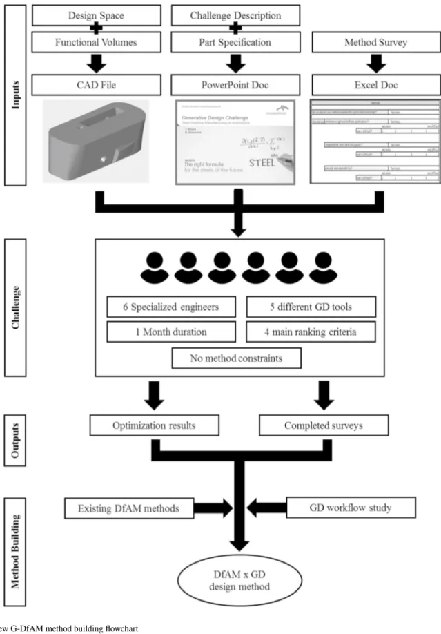
The entire challenge process to develop the new DfAM method is resumed in a flowchart (Fig. 7).
5 A new DfAM method proposition
5.1 Challenge results5.1.1 Solutions ranking
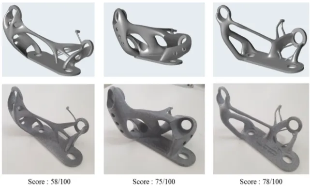
At the end of the challenge phase, six different solutions were presented using five different GD software. The pro-posed solutions offered very different shapes, geometries and performances. This large range of design options obtained is a success for the challenge approach. All the proposed concepts were also printed in a 1:1 scale. The solutions were then rated and ranked according to the challenge criteria (Fig. 8).
5.1.2 Method reviewing
The retrieved methodologies were also quite different. The study of the surveys aimed to determine the similarities, dif-ferences and singularities between the 7 method proposed. The similarities between the participants’ methods helped determining the key points for the new DfAM methodol-ogy. The differences and singularities were also important.
Indeed, among them, the best ideas could be integrated in the new design methodology.
Moreover, solutions with the highest rating tend to maxi-mize the potential of AM and GD. Thus, the methods linked with the solutions’ ranking highlighted the best propositions. To build the new DfAM method, elements from the best proposed method have also been integrated.
5.2 Method proposition 5.2.1 Method building
To finally answer the Research Question: how to include Generative Design in the DfAM, all the proposed phases are essential. The state of the art of DfAM methodologies allowed to understand the new method but also to draw inspiration and ideas out of already existing AM methods. The state of the art of GD helped understanding the optimi-zation tools possibilities, similarities and differences to build in the end a generic GD process workflow. This workflow has been integrated in the new G-DfAM method proposition. The challenge solutions were then ranked along with the challenge methodologies.
5.2.2 A DfAM method integrating generative design proposition
This methodology for GD in DfAM has then been proposed on Fig. 9. The method is divided in 4 successive phases:
the translation, the initialization, the AM guidelines integra-tion and finally the refinement. It helps users addressing the different levels of optimization complexity and eases their workflow.
Each main G-DfAM method step is described and illus-trated with the Seatbelt Bracket Challenge Study Case on Fig. 10.
Fig. 9 G-DfAM methodological proposition
The “translation” phase is the highly important phase in which the specifications are translated into the usual GD tools inputs (design space, non-design zone and load cases).
The “initialization” phase is an unconstrained optimiza-tion phase. Within the given design space, the main goal is to grasp the optimal setting for the runs and have a first draw of an optimal unconstrained solution. To do so, the user can loop in the process of preparing an optimization run, com-puting the run and analysing its results. Looping will help the user refine the settings of the optimization each time he starts the process again. It is advised for the user to go from
coarse settings to fine, so he will save optimization time obtaining a fine solution matching the problem’s constraints. The user can also loop back to the optimization preparation if its optimization results don’t match the part specifications. When the user feels satisfied with the optimization result, he can leave the loop with its best option and proceed to the next step.
The “AM guidelines” integration phase is based on the previous unconstrained result. In this phase the user needs to run new optimizations integrating the AM production specif-icities. For example, to minimize supports, the unconstrained
optimization solution will suggest a draw direction and the machine used an overhang as well as a minimum thickness. These new constraints can then be integrated in the param-eters of the next optimization runs. If the part allows it, the user could also modify its geometry to print two parts in one run, optimizing AM production. In the same way as in the “initialization” phase, looping after analysing is recom-mended to ensure the part specifications validation and to refine the settings, thus the optimization results.
In the last “refinement” phase, the previous AM-opti-mized result can be refined to its limit with meta-structures blending. Doing so, the user will optimize even more the part and save more material, i.e. reducing production cost and time. Analysing the part each loop so the user can push refinement and verify that the problem’s constraints are well respected. This phase exploits the full potential of combined AM and GD tools, indeed GD blend into the part freestand-ing meta-structure exclusive to AM.
6 Conclusion and future work
In this paper we propose a new DfAM method including GD tools.
First, DfAM and Generative Design (GD) were reviewed. Then, a GD workflow is proposed as the result of a challenge approach to confront different software and methodologies.
This method was tested on a first use-case corresponding to the automotive industry (seatbelt bracket). Future work will be to improve the proposed method by implementing new use-cases. Integration of upcoming innovations related to progress in GD and AM will be also considered.
References
1. Wohlers, T., Campbell, R. I., Huff, R., Diegel, O., & Kowen, J.: Wohlers report 2019: 3D printing and additive manufacturing state of the industry. Wohlers Associates (2019)
2. Frazier, W.E.: Metal additive manufacturing: a review. J. Mater. Eng. Perform. 23, 1917–1928 (2014)
3. Gibson, I., Rosen, D.R., Stucker, B.: Additive Manufacturing Technologies. Springer, Berlin (2010)
4. Schnitger, M. An introduction to generative design. Cadalyst. Lon-gitude Media. https ://info.cadal yst.com/ (2018). Accessed May 2020
5. Fischer, X., Nadeau, J.-P.: Research in Interactive Design (Vol. 3): Virtual, Interactive and Integrated Product Design and Manufac-turing for Industrial Innovation. Springer, Berlin (2011) 6. Kuo, T.C., Huang, S.H., Zhang, H.C.: Design for manufacture
and design for ‘X’: concepts, applications, and perspectives. Comput. Ind. Eng. 41(3), 241–260 (2001)
7. Tomiyama, T., Gu, P., Jin, Y., et al.: Design methodologies: industrial and educational applications. CIRP Ann. Manuf. Technol. 58(2), 543–565 (2009)
8. Segonds, F.: Design by additive manufacturing: an applica-tion in aeronautics and defense. Virtual Phys. Prototyp. 13(4), 237–245 (2018)
9. Laverne, F., Segonds, F., Anwer, N., et al.: Assembly based methods to support product innovation in design for additive manufacturing: an exploratory case study. J. Mech. Des. 137, 121701 (2015)
10. Reiher, T., Lindemann, C., Jahnke, U., et al.: Holistic approach for industrializing AM technology: from part selection to test and verification. Prog. Addit. Manuf. 2, 43–55 (2017) 11. Khan, S.: A generative design technique for exploring shape
variations. Adv. Eng. Inform. 38, 712–724 (2018)
12. Krish, S.: A practical generative design method. Comput. Aided Des. 43, 88–100 (2011)
13. Bendsoe, M.P., Sigmund, O.: Topology Optimization: Theory, Methods and Applications. Springer, Berlin (2004)
14. Liu, X., Yi, W.J., Li, Q.S., et al.: Genetic evolutionary structural optimization. J. Constr. Steel 64, 305–311 (2008)
15. Zhao, F.: A nodal variable ESO (BESO) method for structural topology optimization. Finite Elem. Anal. Des. 86, 34–40 (2014)
16. Guo, X., Zhang, W., Zhang, J., et al.: Explicit structural topol-ogy optimization based on moving morphable components (MMC) with curved skeletons. Comput. Methods Appl. Mech. Eng. 310, 711–748 (2016)
17. Wu, J., Quian, X., Wang, M.Y.: Advances in generative design. Comput. Aided Des. 116, 102733 (2019)
18. Danon, B.: How GM and autodesk are using generative design for vehicles of the future. Autodesk. https ://adskn ews.autod esk. com/ (2018). Accessed May 2020
19. Sossous, G., Demoly, F., Montavon, G., et al.: An additive man-ufacturing oriented design approach to mechanical assemblies. J. Comput. Des. Eng. 5, 3–18 (2018)
20. Yang, S., Tang, Y., Zhao, Y.F.: A new part consolidation method to embrace the design freedom of additive manufacturing. J. Manuf. Process. 20, 444–449 (2015)
21. Alexander, P., Allen, S., Dutta, D.: Part orientation and build cost determination in layered manufacturing. Comput. Aided Des.
30(5), 343–356 (1998)
22. Ruffo, M., Hague, R.: Cost estimation for rapid manufacturing simultaneous production of mixed components using laser sinter-ing. Proc. Inst. Mech. B Eng. J. Eng. Manuf. 221(11), 1585–1591 (2007)
23. Likert, R.: A technique for the measurement of attitudes. Arch. Psychol. 140, 1–55 (1932)
24. Smith, S.M.: The constraining effects of initial ideas. Group crea-tivity: Innovation through collaboration, Oxford University Press, pp 15–31 (2003)
Publisher’s Note Springer Nature remains neutral with regard to jurisdictional claims in published maps and institutional affiliations.
![Fig. 1 On left C-DfAM workflow, on right A-DfAM workflow [9]](https://thumb-eu.123doks.com/thumbv2/123doknet/7406983.217915/3.892.179.797.685.1040/fig-left-c-dfam-workflow-right-dfam-workflow.webp)
![Fig. 2 Topology optimization: on the left SIMP method iterations [13], on the upper right ESO method iterations [14], on the bottom right MMC method iterations [16]](https://thumb-eu.123doks.com/thumbv2/123doknet/7406983.217915/4.892.84.812.556.1028/topology-optimization-method-iterations-method-iterations-method-iterations.webp)
![Fig. 3 Multiple design options of the same general motors seat bracket proposed by Autodesk Generative Design tool [18]](https://thumb-eu.123doks.com/thumbv2/123doknet/7406983.217915/5.892.123.764.730.1040/multiple-options-general-bracket-proposed-autodesk-generative-design.webp)