Science Arts & Métiers (SAM)
is an open access repository that collects the work of Arts et Métiers Institute of
Technology researchers and makes it freely available over the web where possible.
This is an author-deposited version published in: https://sam.ensam.eu Handle ID: .http://hdl.handle.net/10985/17118
To cite this version :
Mahenina Remiel FENO, Patrick MARTIN, Bruno DAILLE-LEFEVRE, Alain ETIENNE, Jacques MARSOT, Ali SIADAT - Safety of Manufacturing Equipment: Methodology Based on a Work Situation Model and Need Functional Analysis - 2016
Any correspondence concerning this service should be sent to the repository Administrator : [email protected]
Safety of Manufacturing Equipment:
Methodology Based on a Work Situation Model
and Need Functional Analysis
Mahenina Remiel FENO1, Patrick MARTIN 2* , Bruno
DAILLE-LEFEVRE3, Alain ETIENNE 2, Jacques MARSOT3 Ali SIADAT2
1 Arts et Métiers (ENSAM) Aix en Provence campus, LSIS , 2 cours des Arts et Métiers, 13
617 Aix-en-Provence, France
2 Arts et Métiers (ENSAM) Metz campus, LCFC, 4 rue Augustin Fresnel, 57078 Metz,
France
3 Institut national de recherche et de sécurité (INRS), Work Equipment Engineering
De-partment, 1 rue du Morvan, 54519 Vandœuvre-Lès-Nancy cedex, France
* Corresponding author: Martin Patrick. Tel.:+ (33) 3 87 37 54 65; fax: +(33) 3 87 37 54 70. E-mail address: [email protected]
Abstract: The aim of “integrated prevention” is to conduct a preliminary risk analysis in order to
achieve a lower level of risk in the design of future work equipment. Despite the many safety doc-uments that exist, many companies, particularly SME/SMIs, do not yet apply these safe design principles. Integration of safety in the design process is mainly based on the individual knowledge or experience of the designers and is not conducted in any formalized way. In order to answer to this problem, this paper presents a methodology to involve engaging stakeholders in dynamic dia-logue and a framework so that they may together define the information necessary for implement-ing safe design principles durimplement-ing the functional specification. The proposed methodology has been validated to industrial case.
Keywords: work situation, integrated prevention, requirement specification, need functional
analysis, safe design
1.
Introduction
The concept of “integrated prevention” has been widely shared by European countries since the 1990s (Figure 1). It consists of applying safe design principles as early as possible in the design process. The aim is to conduct a preliminary risk analysis in order to achieve a lower level of risk in the design of future work equipment.
Despite that many safety documents that exist (e.g., design instructions, guides and standards), many companies, particularly SME/SMIs, do not yet apply these safe design principles correctly. This is largely because the different participants in the design process (engineers, technicians, project leaders) are not prevention specialists and lack of appropriate methods and tools. As a result, it is difficult for them to make the correct choices in a timely manner without penalizing the pro-ject cost or delaying propro-ject completion. Consequently, integration of safety in the design process is mainly based on the individual knowledge or experience of the
designers and is not conducted in any formalized way [2]. Safety requirements are usually addressed in formulaic sentences such as “the equipment should respect regulations and standards” or “should be safe, ergonomic and easy to use” etc. As a result, prevention issues and technical requirements are often handled separately and the safety problems are often dealt with at the end of the project once the con-cepts and technical solutions have already been defined. At this point, the measures implemented are mainly corrective, merely to satisfy the regulations. This cannot be considered to constitute true safety integration, which takes into account the future activity of the operators, including “reasonably foreseeable misuse” [3].
Figure 1. Risk reduction process according to NF EN ISO 12100 [1]
In response to this problem, the following methodology involves engaging stakeholders in dynamic dialogue so that they may together define the information necessary for implementing safe design principles during the functional specifica-tion. Usage limit (safety target) Hazard ? Removed ? Protection ? Intrinsic preven-tion Individual or col-lective protection Objective reached Safety level ? Yes No Warning Notice Yes Yes No No No Yes Risk level
2.
State of the art
A number of publications concerning safety integration at the specification stage recommend considering health, safety and ergonomics as design objectives that should be specified in the requirement document. To do so, specifications should go beyond safety recommendations contained in standards and take into account predictable use of the work equipment, for instance by analyzing the ac-tivities of the operators of similar machinery [4] to [8].
Need Functional Analysis (NFA) is a well-known methodological tool stand-ardized [9] that can support the specification stage. While a number of studies have highlighted the benefits of functional analysis in the prevention of risks be-cause of its pluridisciplinary approach [10], others have described its limitations in regard to its ability to specify different contexts of use and future user activities [11].
MOSTRA (Work situation model) resulted from previous INRS research on safety integration in design [12]. The specific objective of this model is to help de-signers to take into account different contexts of use and future user activities. MOSTRA is based on the concept of work situations according to a systemic model described by Guillevic [13], and uses the entities involved in safe working practices. Figure 2 shows the different concepts that designers typically deal with (e.g., system, function, technical solution, consumables) and MOSTRA allows them to consider those concepts that mainly concern the users, the tasks to be per-formed, and the associated risks (for example, dangerous zones, hazards, danger-ous events, or safety measures).
The model cannot manage the design process by itself but, in order to exploit it, it is necessary to use it in conjunction with traditional design tools. Through such a combined approach, the methodology relevance is assured by the logical use of the traditional tools and the data consistency is provided by MOSTRA.
3.
Specification methodology for safe design
In order to achieve our goal, we decided to use the “MOSTRA” model to form a link between the functions identified with NFA and the work-situation parame-ters needed for the risk assessment.
3.1.
NFA and safety requirements
Safety requirements may be integrated in the functional analysis at three possi-ble levels, the choice of which can lead to different results:
• General constraints: as enacted by EN 1325-1 [9], however, although this is necessary, it is not sufficiently detailed and may lead to the designer developing the prevention apart from the technical and functional requirements,
• Function: this approach is relevant only when the objective is to design a safe-ty-related system. However, integration at the functional level leads designers to specify the prevention separately from the functional requirement.
• Function performance criteria: the goal is to identify all parameters which have a direct impact on safety. The functional decomposition of the system is then used to define the future user tasks on the work equipment.
We will continue with this last approach in our methodology. The “us-er/designer” should be guided to obtain a complete picture of a design task. Alt-hough they naturally provide the foundation on which to focus design efforts, there are other important criteria that the user may not even perceive, such as safe-ty issues. Otto and Wood [14] define these as latent specifications (needed, but not always expressed by the customer). To do this, it is necessary to ask what the pos-sible work situations are and which entities are involved for each function. The second stage of NFA method therefore needs to be divided into two different phases: description and characterization.
3.2.
Description step
The description phase should be carried out by a work team (designers, users, project leader), with the help of a structured and easy-to-use questionnaire which collects all information, including latent information. At this point it is necessary to decide whether it is better to:
• Directly use MOSTRA links to build the questionnaire and gather information about work situations such as “Environment”, “User task”, “Work team”, etc.
• Use a tool such as “5Ws and an H”, which is often used in industrial problem solving [15]. The work team must answer “What”, “Who”, “Where”, “When”, “Why” and “How” the function is accomplished. This tool uses an intuitive, de-scriptive and imaginative way to describe the work situation because it uses basic
question prompts thereby generating answers in natural language. Firstly an ex-ploratory test was conducted so that these two approaches could be compared. A case study of band saw machines for the food industry was chosen, and two study groups were formed. Each group was composed of two technical designers and an ergonomist, who each had the same level of knowledge of the case study. In both questionnaires the participants were asked to specify four functions (F1: set-up the blade, F2: remove the blade, F3: cutting meat, F4: cleaning the machine). The first team started with functional analysis and the “5Ws and an H” questionnaire, while the second started with the MOSTRA-based questionnaire.
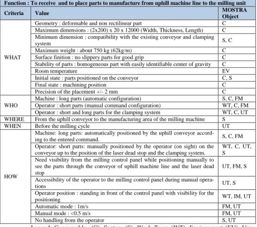
Table 1. Functional chart – Industrial application
Function : To receive and to place parts to manufacture from uphill machine line to the milling unit
Criteria Value MOSTRA
Object
WHAT
Geometry : deformable and non rectilinear part C
Maximum dimensions : (2x200) x 20 x 12000 (Width, Thickness, Length) C Minimum dimension : compatibility with the existing conveyor and clamping
system S, C
Maximum weight : about 750 kg (62kg/m) C
Surface finition : no slippery parts for good grip C
Stability of parts : homogeneous part with easily identifiable center of gravity C
Room temperature EV
Initial state : parts positioned on the conveyor C, S
Final state : machining position C
Precision of the placement +/- 2 mm C
WHO
Machine : long parts (automatic configuration) S, C, FM
Operator : short parts (manual command configuration) WT, C, FM Operator : short and long parts for the clamping system WT, C, UT WHERE From the uphill conveyor to the manufacturing area of the milling machine S
WHEN Before the milling cycle UT
HOW
Machine: long parts: automatically positioned by the uphill conveyor
accord-ing to the entered command. S, C, FM
Operator: short parts: manually positioned by the operator (on sight) on the conveyor up to the position of the laser dead stop and the clamping system.
WT, C, UT, S
Need visibility from the milling control panel while positioning manually to see the parts through the conveyor of uphill machine line and the laser dead stop
UT, FM, S Accessibility of the operator to the milling control panel during manual
opera-tions UT, S
Operator position : standing in front of the control panel with visibility for the
positioning WT, IM, UT
Automatic mode : 1m/s FM, UT
Manual mode : <0.5 m/s FM, UT
No handling from the operator S, UT
Legend: Consumable (C), System (S), Work Team (WT), Environment (EV), User Task (UT), Tool (T), Intervention Mode (IM), Functioning Mode (FM)
This test shows that the “5Ws and an H” questionnaire overlap those of the MOSTRA. We therefore recommend using the “5Ws and an H” questionnaire for the description step. The MOSTRA-based questionnaire will be used during the characterization step. A chart was created to orientate the group discussion
to-wards achieving our objectives. Then an industrial case study: company that de-signs and manufactures both specialized and standard machines with several op-tional functions (drilling, stamping, and sawing machining transfer line) for work-ing with steel beams, was performed (Table 1).
3.3.
Characterization step
The objective of the characterization step is to define the performance criteria that characterize each previously identified entity. Each performance criterion, specially health, safety and ergonomic aspects, should be measurable, testable or verifiable at each successive step in the development process [14]. To achieve this, it is necessary to first associate one or several MOSTRA objects with each de-scription according to what it characterizes. To do this the “5Ws and an H” were mapped with MOSTRA objects and then MOSTRA-based questionnaire allows completion and verification of the data coherence with regard to the function con-cerned. These associations allow identification of the main working situations in which the function is effective. The structure used to define the working situations is illustrated in Table 2.
Table 2 - Data structure of main work situations – industrial case
F: Receive and place parts to manufacture from uphill machining transfer line to the milling unit.
|_ WS1: Automatic positioning for long parts |_ UT1: Placing parts
|_ C1: Long parts |_ S4: Conveyor of the line
|_ FM2: Automatic mode
|_ WS2: Manual positioning for short parts |_ UT1: Placing parts
|_ WT: Operator |_ IM1: Standing posture |_ C2: Short parts |_ FM1: Manual mode
|_ WS3: Manual command of
the clamping
|_ UT5: Clamping the parts
|_ C1: Short parts |_ C2: Long parts |_ S2: Clamping system
The final step is to add a quantitative or qualitative value to each criterion. These can be either predefined attributes of the Mostra UML model (task name, duration, work team, intervention mode) or specific parameters (initial/final state, speed …). This step facilitates and enhances the risk analysis, which should be carried out iteratively according to NFA progress. Within the framework of this study we used the IDAR® method developed by CETIM [16]. Based on the EN12100 standard approach, this method has a specifically user- centered and human-safety oriented analysis, which matches our objectives.
3.4.
Discussion
We describe the solutions implemented with regard to the following function: to receive and to place parts to manufacture from uphill machining transfer line to
the milling unit (Table 1). According to the part length, two operating modes were initially defined by the industrial partner: manual and automatic. In answering the “5Ws and an H” questions, the designers realized that the technical solutions re-tained for these two operating modes were not entirely satisfactory from a safety point of view. For the short part, the operator needs to control and simultaneously visualize the part’s positioning. The current location of the control panel leads to an uncomfortable position for the operator. In addition, the transferring wheels were designed for parts longer than 300 mm, but when answering the “What” question, it was stated that some customers produced shorter parts (250mm). In these situations, the operator has to handle the parts manually, risking a hand be-ing crushed between the part (25 kg) and the transferrbe-ing wheels.
Another safety issue highlighted by the proposed methodology concerned the possible interactions during the loading/unloading phase. It quickly became appar-ent that the end-user would perform this operation during the production time, when the machine was operating in an automatic mode for a period of several minutes and did not require the intervention of the operator. This working practice comes under the definition of “reasonably foreseeable misuse” in the Machinery Directive and must also be taken into account by the designer; this was not the case in the initial design. As the preparation area was located close to the convey-or, its access was also prevented by the safety device. However, it seems highly likely that it will be bypassed at some time in the future due to productivity con-straints.
4.
Conclusion
The aim of this research work is to use the “user/designer” pair to define the in-formation necessary (intermediary objects [17]) for integrating safety require-ments at the specification stage. Our hypothesis is to integrate safety requirerequire-ments as performance criteria for each function and not as specific functions or general requirements, in other words, to specify that each function should be safe. We suggest using:
1. Need Functional Analysis, which is used to identify all functions of a future product (work equipment in our case).
2. An intuitive and descriptive tool such as “5Ws and an H” to define, for each function, the usage-based criteria including safety criteria.
3. The MOSTRA working situation model to organize and capitalize these data. This model was specifically developed to support safety integration at the design stage.
In addition to the specific benefits of traditional functional analysis (e.g., sav-ing time in the subsequent design-process steps, possibility of capitalizsav-ing the re-sults of the analysis etc.), the proposed approach creates a common basis for both NFA and risk analysis. The first industrial application yielded relevant results: un-safe work situations were identified that had not been detected in the original
de-sign by the industrial partner. However, this case study only allowed validation of the potential benefits from a designer’s point of view. Data was mainly provided by the designers and few data were supplied by the final user.
This work has been performed in the frame of the dual laboratory between INRS and ENSAM/ LCFC (safety design of working situation: functional re-quirements, equipment design, working place management).
References
1. NF EN ISO 12100: Safety of machinery —General principles for design —Risk assessment and risk reduction, CEN, Bruxelles, 2010
2. Fadier E., De La Garza C. (2006) - Safety design: Towards a new philosophy. Safety Sci-ence, 44, Issue 1, 2006, pp. 55-73
3. Directive 2006/42/CE , the European parliament and of the council of 9 June 2006 on the approximation of the laws of the member states relating to machinery, Official Journal Law, L157-24 to L157-86., 2006
4. Prudhomme G., Zwolinski P., Brissaud D. Integrating into the design process the needs of those involved in the product life-cycle Journal of Engineering Design, vol. 14-3, 2003, pp. 333-353.
5. Sagot J.C., Gouin V., Gomes S. Ergonomics in product design: safety factor. Safety Sci-ence, 41, 2003, pp. 137-154.
6. Ghemraoui R., Mathieu L, Tricot N. Design method for systematic safety integration, CIRP Annals - Manufacturing Technology 58, 2009, pp.161-164
7. Moraes A.S.P., Arezes P. M., Vasconcelos R., From ergonomics to design specifications: contributions to the design of a processing machine in a tire company, IEA 2012: 18th World congress on Ergonomics - Designing a sustainable future, IOS Press 2012, pp. 552-559 8. Darses F., Wolff M., How do designers represent to themselves the users' needs?, Applied
Ergonomics 37(6), 2006, pp. 757-764.
9. EN 1325-1 Value management, value analysis, functional analysis vocabulary. Value analy-sis and functional analyanaly-sis, CEN, Bruxelles, 1997.
10. Marsot J., Claudon L. Design and Ergonomics - Methods and Tools for integrating ergonom-ics at the design stage of hand tools. International Journal of Occupational Safety and Ergo-nomics, 10(1), 2004, pp.11-21.
11. Fadier E., Neboit M. Essai d’intégration de l’analyse ergonomique de l’activité dans l’analyse de la fiabilité opérationnelle pour la conception: approche méthodologique. Actes du colloque «Recherche et Ergonomie», Toulouse, 1998, pp. 61-66.
12. Hasan R., Bernard A., Ciccotelli J., Martin P., Integrating safety into the design process: el-ements and concepts relative to the working situation. Safety Science - Special issue « Safety in design », 41(2-3), 2003, pp. 155-180.
13. Guillevic C., Psychologie du travail, Éditions Nathan, collection Fac Psychologie, Paris, 1991,225 p.
14. Otto K., Wood, K., Product Design: Techniques in Reverse Engineering and New Product Development, Prentice Hall, Upper Saddle River, NJ 07458, 2001
15. Tapan K. Bose, (2010) - Total Quality of Management. Chapter 10. Basic Decision-making and Problem-solving Tools. Pearson Education India. ISBN: 978-8-131-70022-8.
16. Falconnet – Dequaire E., Meleton L. (2001) - IDAR®: une méthode d'analyse des risques dans le cadre de la directive Machines, CETIM, Senlis, 2001, 164 p.
17. Boujut JF, Blanco E. Intermediary Objects as a Means to Foster Co-operation in Engineering Design. Journal of computer supported collaborative; 2002. 12 (2):205-219.
![Figure 1. Risk reduction process according to NF EN ISO 12100 [1]](https://thumb-eu.123doks.com/thumbv2/123doknet/7373852.214930/3.892.179.743.434.820/figure-risk-reduction-process-according-nf-en-iso.webp)
![Figure 2 Simplified view of MOSTRA [13]](https://thumb-eu.123doks.com/thumbv2/123doknet/7373852.214930/4.892.257.623.675.974/figure-simplified-view-mostra.webp)