Science Arts & Métiers (SAM)
is an open access repository that collects the work of Arts et Métiers Institute of
Technology researchers and makes it freely available over the web where possible.
This is an author-deposited version published in:
https://sam.ensam.eu
Handle ID: .
http://hdl.handle.net/10985/8704
To cite this version :
Zhibin ZHOU, Franck SCUILLER, Jean-Frederic CHARPENTIER, Mohamed BENBOUZID,
Tianhao TANG - Grid-Connected Marine Current Generation System Power Smoothing Control
Using Supercapacitors - In: IECON 2012-38th Annual Conference on IEEE Industrial Electronics
Society, Canada, 2012-10 - IECON 2012-38th Annual Conference on IEEE Industrial Electronics
Society - 2012
Any correspondence concerning this service should be sent to the repository
Administrator :
[email protected]
Grid-Connected Marine Current Generation System
Power Smoothing Control Using Supercapacitors
Zhibin Zhou, Franck Scuiller, Jean Frederic Charpentier, Mohamed Benbouzid and Tianhao Tang
Abstract-Swell is the main disturbance for marine tidal speed. The power harnessed by a marine current turbine (MCT) can be highly fluctuant due to swell effect. Conventional Maximum Power Point Tracking (MPPT) algorithm will require the generator to accelerate/decelerate frequently under swell effect and therefore cause severe fluctuations in the generator power. This paper deals with power smoothing control of grid connected MCT system. In the first step, a modified MPPT algorithm with filter strategy is proposed in the generator side control to reduce the fluctuation of generator power. In the second step, Supercapacitor (SC) Energy Storage System (ESS) is added to compensate the residual power fluctuations. As the average tidal speed is predictable, it is possible to control the SC ESS to compensate the swell effect and realize a smoothed power injected to the grid.
Simulations carried-out on a 1.5 MW direct-driven grid connected MCT generation system demonstrate that the association of the generator side filter strategy with the SC ESS system achieves a smoothed grid-injected power in case of swell disturbances.
Index Terms-Marine current turbine, power fluctuation, swell effect, power smoothing control, supercapacitor.
I. [NTRODUCTION
[n the recent years, various turbine technologies have been developed to capture kinetic energy from marine and tidal currents [[]. Exploitable marine currents are mostly driven by the tide, which causes seawater motion regularly each day with a period of approximately 12 h and 24 min (a semi diurnal tide), or with a period of about 24 h and 48 min (a diurnal tide). The astronomic nature of tides makes marine current resource highly predictable with 98% accuracy for decades [2]. The main disturbance for the tide is the swell which causes marine current speed fluctuates on a period about [0 to 20 s. The swell effect will cause the power harnessed by the MCT and the generator to be highly
Z. Zhou, F. Scuiller and .l.F. Charpentier are with the French Naval Academy, IRENav EA 3634, 29240 Brest Cedex 9, France (e-mail: [email protected], Francie Scui [email protected], Jean [email protected],). Z. Zhou is also with the University of Brest and the Shanghai Maritime University.
M.E.H. Benbouzid is with the University of Brest, EA 4325 LBMS, Rue de Kergoat, CS 93837, 29238 Brest Cedex 03, France (e-mail: [email protected]).
T. Tang is with the Shanghai Maritime University, 201306 Shanghai, China (email: [email protected]).
This work is supported by Brest Metropole Oceane (BMO).
Pgenerator Pgrid
� �
Tide and Swell
-PMSG
MCT
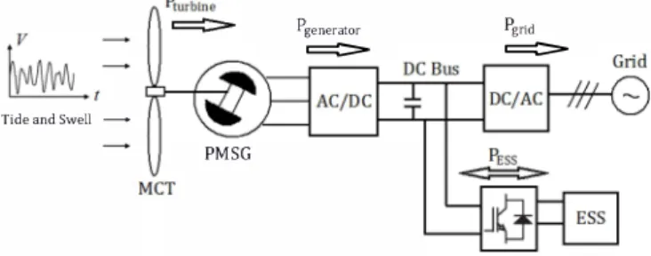
Fig. l. General scheme for a direct-drive MCT system with ESS.
fluctuant. This phenomenon deteriorates the quality of power injected into the grid from the MCT generation system.
Energy storage system (ESS) is assumed to be a good solution to smooth power fluctuations, improve the system reliability and provide auxiliary services to the grid [3-4]. In this paper, one 1.5 MW grid-connected MCT generation system is studied. Fig. I shows the general system structure. Permanent magnet synchronous generator (PMSG) is chosen as the generator which is connected to the grid through a full sized back-to-back converter. Supercapacitor (SC) is chosen as the ESS type for its high power and high dynamics characteristics [5].
[n Section II, the swell effect and marine current speed model are described. [n Section III, the turbine model and the generator-side power smooth control strategy with filter algorithm are presented. [n Section [V, the grid-side converter control scheme is illustrated and in Section V, the supercapacitor control and the simulation results are presented. The conclusion is given in Section VI.
[[. MARINE CURRENT SPEED MODELING
The marine current speed is driven by the tide and the swell. In this paper, the first order Stokes model [6] and JONSW AP spectrum [7] are used to model the swell effect. The total marine current speed is calculated by
_ 2rrai Ch
(
2rr¥f-)
(
t x)
Vet) - Vtide
+L;-
(
d)
cos2n -- - + ((l;(1)
Ti
sh 2rr-L;Ti Li
[t contains two parts: the first item
Vtide
represents the predicted tidal speed, and it can be regarded as a constant (which is set to 2m/s in this paper) during a period less than an hour; the second term represents the harmonic current speeds caused by the swell.z
o
Fig. 2. Swell characteristic.
L Swell length H, Swell height
d, Sea depth
Fig. 2 shows the main characteristic of the swell: x and z
components represent the horizontal and vertical point for the calculation; d is the sea depth; Hand L represent the height and length of the swell. Swells refer to ocean waves which propagated over a very long distance after their generating area. This makes swells more stable and regular than normal wind sea waves. In order to model a realistic swell effect, more than one frequency component should be considered. That explains the superposition calculation in the second term of ( 1). The parameters are calculated based on the wave theory and the swell spectrum. The <Pi represents the initial phase angle of each frequency component which is given randomly.
The swell spectrum can be calculated based on the JONSWAP spectrum as follow.
Where, Hi 1 4 1 1 Y
Sct)
=�J
T4fS
expC
-5 T4fS)y
P P 0.0624(1.094-0.0195 In y)�J
= 0.23+0.0336y-0.185(1.9+y)[
(Tpf-1)2
]
.
_{0.07,
Y = exp -� wIth G -0.09,
(2)In the simulation, the sea state of H, = 3 m, Tp = 13.2 s is
considered, and y =
7
is chosen in the (2). Swells have a verynarrow range of frequencies so that only a few frequencies need to be chosen for the modeling. The amplitude of each frequency components can be calculated by ai =
.J2S(fi)fj,fi .
Fig. 3 shows the simulation curve of marine current speed under swell effect. In the simulations, the MCT is supposed to be located at a sea depth of 35 m and the marine current speed is calculated at a depth of 22 m below the sea surface. � u Q) OIl -...
S
"0 Q) Q) 0-U'l ... .: Q) ... ...:=
u
0
.
5
1
00
200
300
400
Time (sec)Fig. 3. Marine current speed with swell eflect.
500
600
1500
� 1000
6 ....�
�500
o 1\IV
IV
inI
�
100
�
II�
I A.H
\W
IIV
rr
\,
'
1'
1\
�
�
200
300
400
Time (sec) -Prodl.<e<lPClllerI
----+-Average Power - - -Witoou Swel ,A�
I11J
�
.
I
q
�
500
600
Fig. 4. Power profile for a marine current turbine.
Fig. 4 shows the estimated produced power of a 1.5 MW horizontal-axis marine current turbine. It can be seen that the swell effect can cause large power fluctuation in the turbine harnessed power, and it may also increase the available tidal energy. The main challenge of connecting the marine current generation system to the power grid is to obtain a stable and smoothed power.
III. MARINE CURRENT TURBINE AND GENERATOR CONTROL A. Marine Current Turbine Model
The power harnessed by a horizontal-axis MCT can be calculated by the following equation.
(3) In (3), the sea water density p and the turbine radius Rare considered as constants; V is the marine current speed; Cp is the turbine power coefficient which depends on the turbine blade structure and its hydrodynamics. For typical MCTs, the optimal Cp value for normal operation is estimated to be in the range of 0.35-0.5 [2]. For a given turbine and based on the experimental results, the Cp curve can be numerically approximated as a function of the tip speed ratio ( Ie = Wrn
V
/R
)and the blade pitch angle [8]. In this paper, the MCT is not pitched. The Cp curve for simulations is shown by Fig. 5.
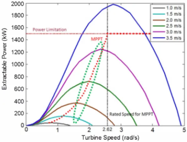
In this paper, a 1.5 MW direct-driven MCT with 8 m of radius is studied. The turbine maximum speed to follow MPPT is 25 rpm (2.62 rad/s) for a marine current of 3.2 m/s. If the marine current exceeds 3.2 mis, the extracted power
0.5 0.45 0.4 0.35 a. 0.3 u 0.25 0.2 0.1 5 o. 1 0.0 5 0
./
/
/
/
/
//
/'
�
6 Lamda\
\
\
,\\
\
\
10 Fig. 5. Cp curve of the marine current turbine.12
2000 r---�--�-"""'7:;:-r----r==='J 1800 � 1600 � � 1400
�
1200 � 1000 '"�
800 ;n 600 400 200 °O�������--��-i-��-�Turbine Speed (radls) Fig. 6. The MCT extractable power.
will be limited to 1.5 MW. The turbine extractable power under different marine current speeds is calculated by (3) and illustrated by Fig. 6. In this figure, the red dotted curve is the conventional MPPT curve; the green dashed ellipse shows the proposed modified MPPT with filter strategy to avoid fast acceleration/deceleration of the system for decreasing the generator power fluctuation.
B. Marine Current Generator Model
The advantages of PMSG are compact structure, high efficiency and the possibility to eliminate the gearbox. This is very favorable in terms of underwater application.
PMSG dynamic model is given in a synchronous rotation d-q frame. Equation (5) shows the Park transform used in the generator side part. The d-axis is oriented to the rotor flux axis and the e is the electrical angle between stator phase a and the d-axis.
[Vd]
2[
cos 8Vq
= 3' - sin8 cos (8 _ 2TI)
3 _ sin(8 _ 2TI)
3 2TI1 [va
cos (8+-);
TIVb
-sin (8 +-) 3Vc
The PMSG model in the d-q frame can be described by the following equations.C. Generator Side Control Strategy
(5)
(6)
The control of the generator aims to track the reference rotor speed to achieve the expected power extracted by the MCT. The rotor speed is controlled by the generator torque, which is controlled by the q-axis current through the generator-side converter.
Fig. 7. Control scheme of the generator-side converter.
Fig. 7 shows the control scheme for the generator-side converter. The d-axis current reference is set to zero for maximizing the active power in the generator. The q-axis current reference is calculated by the speed loop controller.
MPPT consists in controlling the rotor speed to keep the turbine tip speed ratio Ie at its optimal value, thus keeping the turbine power coefficient Cp at the maximum value. Supposing that the Cp curve is known and the marine current speed V can be obtained by flow velocity measurements, the turbine speed reference calculated by the conventional MPPT can be expressed as Aopt
V
/R .
In this paper, a low pass filter is added to filter the rotor speed reference calculated by the conventional MPPT algorithm. The proposed strategy produces the speed reference as
1 AoptV
Wm ref =
Ts+l . -R- (7)
where the T is the filter time constant and plays a significant role in reducing the generator power fluctuation. Setting T to zero leads (7) to the conventional MPPT algorithm.
With the conventional MPPT, the generator power will fluctuate more severely than the turbine power under swell effect. This can be explained as follow: when we neglect the friction losses in the torque equation in (6), we can get
T - T ill e = JdWm
dt dWm
Pturbine - Pgenerator = Wm T m - Wm Te = Wm J ill
This equation can be can be rewritten as
Pturbine - I1P = Pgenerator
(8)
(9) where the difference between the turbine and the generator
. Jdwm
power IS llP = Wm dt'
The power difference I1P mainly depends on the system inertia J and the rotor speed change rate dWm for a low speed dt and large inertia MCT system (as in our case). Since the system inertia is a constant, dWm becomes a decisive factor dt for the value of llP.
When the marine current speed is constant or changes very slowly, llP can be zero or very small for there is no fast
changes in the generator rotation speed. This explains that
PtuTbine and Pgenerator are almost equal at steady state.
When the marine current speed changes rapidly under swell effect, the rotor speed will also change rapidly in the conventional MPPT control;
d:tm
is then not negligible. During the acceleration, I1P is positive and this means that some of the turbine power will be stored by the system inertia and the remaining power will pass to the generator. This causes the generator power to be smaller than the turbine power. In the extreme cases, the required power difference I1Pcan be larger than PtuTbine' This could lead the generator to absorb power as in motor operation.
During the deceleration, I1P is negative which means that the system inertia will release some mechanical power and this part of power will combine with the turbine power to contribute to the generator power. This makes the generator power larger than the turbine power.
Considering a system of very large inertia
(j
= 1.313 X10⁶ kg . m2 ) ,I1P can be very large. The above analyses are
confirmed by the simulation results shown in Fig. 8 and 9. In this case, we suppose the marine current speed starts at 0 m/s and rises to 2m1s in the first 10 sec; the swell effect is considered after 20 sec. Although this is not very realistic for real marine current, it enables to study the starting stage, constant marine current stage, and the fluctuant marine current stage in one simulation.
In the starting stage, it is reasonable to accelerate the generator and turbine to a certain speed for realizing the MPPT quickly. Therefore at the beginning, the generator power can be negative which means that the generator works as a motor temporarily for fast acceleration. In steady state,
Pgenerator and Pturbine are almost equal. Under swell effect,
Pgenerator fluctuates more severely than Pturbine .
3.5 ,---�--�---,___---__:_--__,
--_. Marine Current Speed (m/sec)
3 -Rotor Speed Reference (rad/sec)
2.5
0.5
OL-__ � __ � ___ � __ � ___ � __ �
o W W W 00 � �
Time (sec)
Fig. 8. Rotor speed reference calculated by conventional MPPT.
1400r---,---,---.----�I--r==;=;c='i1 ... OJ :: o c.. 1200 20 '0 60 Time (sec) BO 100
Fig. 9. Turbine and generator power with conventional MPPT. 120 1:00
�
� 1000 ...�
o c.. 500 ... B '" ... OJ <:: OJ " ----·T:::() sec . ... T=1 sec -T=7 sec ----T=14 sec , ---1= 56 secI
1/ .,')J{) �--��---�'O�--�ffi�--�BO---�,OO�--�,� Time (sec)Fig. 10. Generator powers with different filter time constants.
1W0r----,---.----,----.---���� 1200 1000
�
BOO ..>: � '00 ...�
'00 o c.. ·wo 20 40 60 80 100 120 Time (sec)Fig. II. Turbine and generator power with optimized filter time T=7 s.
By adding a low pass filter as shown in (7),
dWm
can bedt
reduced; and the acceleration and deceleration moments of the rotor can controlled to de synchronize with the turbine power change. This means that the system inertia can be used to reduce the generator power fluctuation.
Fig. 10 shows the generator power profiles with different filter time constants. In order to obtain the smallest fluctuations in the generator power, the optimal filter time constant is found as 7 s which equals about half of the typical swell period.
Fig. 1 1 shows the turbine and the generator power profiles using the optimized filter. Compared to the conventional MPPT power profile shown in Fig. 9, the generator power fluctuation is greatly reduced while the turbine harnessed power is not reduced much.
DeBus GConverter rid·side Grid
Fig. 12. Control scheme of the grid-side converter.
[v. GIRD-SIDE CONVERTER CONTROL
The circuit and the control scheme of grid-connection part are shown in Fig. 12. The main function of the grid-side converter is to keep the DC bus voltage stable and to regulate the active and reactive grid-injected power. The dynamic model for the grid-connection part in d-q frame can be written as
For the grid part, the d-axis is oriented to the grid voltage vector, and the grid active power is controlled by the d-axis current. The q-axis current reference is set to zero when there is no grid reactive power requirement. The outside DC bus voltage loop is to keep the DC bus voltage at a given value and to produce the d-axis current reference.
V. SUPERCAPACITOR FOR GRID POWER SMOOTHING
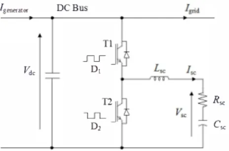
The SC ESS is connected to the DC bus with a bi directional current DCIDC converter (so-called buck-boost chopper). Fig.
[3
shows the main structure of the SC part: the supercapacitor is modeled by a large capacitoresc
in series with a small resistanceRsc ; Lsc
is the buffer inductor ; Dj andDz are the duty ratios for the two switches of the bidirectional DC/DC converter.
[f the converters losses are neglected, the power from the SC can be expressed as follows:
Psc(t)
=Pgenerator(t) - Pgrid(t)
( 1 1 )The SC aims to compensate the generator power fluctuation due to the swell. As the average tidal speed is predictable, the expected grid-inj ected power can be estimated based on the tidal speed. The SC is then controlled to absorb the difference between the generator produced
19=er:ator DeBus
SC:1J
Vd< DJ
-U:-J
R�D, C�
Fig. 13. Supercapacitor and the bidirectional DC/DC converter.
Fig. 14. Control scheme of the bidirectional DCIDC converter.
power and the expected power transferred to the grid. Based on the buck-boost control [9], the supercapacitor voltage can be controlled as
The State of Charge (SoC) of the SC is calculated by,
SoC
= �=
o.scscvlc
=(�)2
([3)
Erated o.scsCv/ated
Vrated
From ( 12) and
([3),
the control signal D (duty ratio) can be deduced as,D =
Vrated"';SoC
Vdc
( 14)Fig. 14 shows the duty ratio control scheme. When [grid> [targeb the duty ratio will rise to increase the SC voltage and make the SC absorb the power from the DC bus. When 19lid <
ltargeb the SC voltage will decrease to make SC release the stored power. ltarget is the current reference representing the smoothed DC current that we expect to transmit to the grid side converter. §: 1000 ... " '" .... .... " U '0 " '" � -200 '" -400 bO 2 "0 > 1000 $ 800 <:: OJ 600 400 .... .... " 200 U '0 " '" � � -200 -400 £9 -600 -0 >- -800 Fig. 15. m w � Time (sec)
Grid phase voltage and current (without ESS).
Time (sec)
Fig. 16. Smoothed grid phase current by the supercapacitor.
0.9 0.8 '" OD .... 0.7 '" .c u 0.6 4-0 a 2J 0.5 2 <.Il 0.4 0.3 020 20 Fig. 40 60 80 Time (sec) 17. Supercapacitor SoC. 100 120
1500,----.---.---.---.---r= __ = __ �T�"m�i=ne� -Generator -Grid -ESS 1000 20 40 60 M 100 120 Time (sec)
Fig. 18. Powers in different parts of the system.
Fig. 15 and 16 show the grid phase voltage and current simulation waveforms. The grid voltage magnitude is assumed to be constant, thereby the variations of grid current magnitude can reflect the fluctuations of the grid-injected power. Therefore, Fig. 16 illustrates the SC ability to alleviate grid power fluctuations: the power transferred into the grid is significantly smoothed.
Fig. 17 shows the SC SoC variations. The initial SoC is set to 0.5, and the SC module is activated after 20 sec (when the swell effect is introduced). Fig. 18 illustrates the powers in different parts of the system. The active grid power IS
shown in this figure since the grid reactive power is controlled to be zero by the grid-side converter.
VI. CONCLUSION
Marine tidal speed can be severely disturbed by the swell, which makes the total marine current speed be highly fluctuant. This phenomenon can cause large power fluctuations in a marine current turbine generation system. Conventional MPPT algorithm can cause more severe generator power fluctuations under the swell effect as clearly shown in this paper. The effectiveness of the proposed modified MPPT algorithm with filter strategy has been confirmed by simulations. Indeed, the achieved results have shown the ability to greatly reduce the generator power fluctuations. The remaining generator power fluctuations are further compensated by integrating supercapacitor module as the energy storage system. The duty ratio of the super capacitor side bidirectional DC/DC converter is controlled by the charge/discharge requirements to absorb the fast power fluctuations. The obtained simulation results show the efficient operation of the supercapacitor that leads to a great reduction of grid power fluctuations.
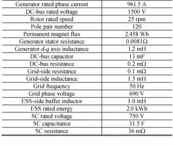
ApPENDIX TABLE I SYSTEM PARAMETER LIST Sea depth
Depth for swell effect calculation Turbine blade radius
35 m 22 m 8 m System total inertia 1.3131 x 10⁶ kg· m2
Generator rated power 1.5 MW
Generator rated phase voltage 520V
Generator rated EMF 546 V
Generator rated phase current 961.5 A
DC-bus rated voltage 1500 V
Rotor rated speed 25 rpm
Pole pair number 120
Permanent magnet flux 2.458 Wb
Generator stator resistance 0.0081Q
Generator d-q axis inductance 1.2 mH
DC-bus capacitor 13 mF
DC-bus resistance O.2 mn
Grid-side resistance 0.1 mn
Grid-side inductance 1.5 mH
Grid frequency 50 Hz
Grid phase voltage 690V
ESS-side buffer inductor 1.0 mH
ESS rated energy 2.0 kWh
SC rated voltage 750 V
SC capacitance 31.5 F
SC resistance 36 mn
TABLE II PI CONTROLLER PARAMETERS
Generator speed loop Kp = 87000,Ki= 7.9 Generator d-axis current loop Kp = 3.4, Ki = 455 Generator q-axis current loop Kp = 3.4, Ki = 455
DC-bus voltage loop Kp= 3, Ki =25
Grid d-axis current loop Kp = 0.2, Ki = 50 Grid q-axis current loop Kp = 0.2, Ki = 50 Supercapacitor current loop Kp = 70, K, = 130
REFERENCES
[I] S. Benelghali, M.E.H. Benbouzid and 1. F. Charpentier, "Marine tidal current electric power generation technology: State of the art and current status," in Proceedings of the 2007 IEEE IEMDC, Antalya (Turkey), vol. 2, pp. 1407-1412, May 2007.
[2] S. Benelghali, R. Balme, K. Le Saux, M.E.H. Benbouzid, 1.F. Charpentier and F. Hauville, "A simulation model for the evaluation of the electrical power potential harnessed by a marine current turbine,"
IEEE Journal on Oceanic Engineering, vol. 32, n04, pp. 786-797, October 2007.
[3] H. Ibrahim, A. I1inca and 1. Perron, "Energy storage systems Characteristics and comparisons," Renewable and Sustainable Energy Reviews, vol. 12, n05, pp.1221-1250, June 2008.
[4] S. Vazquez, S.M. Lukic, E. Galvan, L.G. Franquelo and J.M. Carrasco, "Energy storage systems for transport and grid applications," IEEE Trans. Industrial Electronics, vol. 57, n012, pp.3881-3895, December 2010.
[5] Z. Zhou, M.E.H. Benbouzid, 1.F. Charpentier, F. Scuiller and T. Tang, "Energy storage technologies for smoothing power fluctuations in marine current turbines," in Proceedings of the 2012 IEEE ISlE,
Hangzhou (China), May 2012.
[6] R. Bonnefille, Mouvements de la Mer (in French). Techniques de /'Ingenieur, C4610, pp.I-19, 2010.
[7] Y. Goda, Random Seas and Design of Maritime Structures. Advanced Series on Ocean Engineering, vo1.33, World Scientific: Singapore, 2010. [8] J.G. Slootweg, S.W.H. de Haan, H. Polinder and W.L. Kling, "General
model for representing variable speed wind turbines in power system dynamics simulations," IEEE Trans. Power Systems, vol. 18, nOI, pp.144-151, February 2003.
[9] M. Ortuzar, 1. Dixon and 1. Moreno, "Design, construction and performance of a buck-boost converter for an ultracapacitor-based auxiliary energy system for electric vehicles," in Proceedings of the
2003 IEEE IECOH, Roanoke (USA), pp. 2889-2894, November 2003.