Science Arts & Métiers (SAM)
is an open access repository that collects the work of Arts et Métiers Institute of
Technology researchers and makes it freely available over the web where possible.
This is an author-deposited version published in: https://sam.ensam.eu Handle ID: .http://hdl.handle.net/10985/6520
To cite this version :
Cyrille SOLLOGOUB, Alain GUINAULT - Evolution of polymer blend morphologies during extrusion in a flat die - 2009
Any correspondence concerning this service should be sent to the repository Administrator : archiveouverte@ensam.eu
____________________
* Corresponding author: 292, rue Saint Martin - 75141 Paris Cedex 03 – France – Tel.: + 33(0)1 40 27 24 01 cyrille.sollogoub@cnam.fr
EVOLUTION OF POLYMER BLEND MORPHOLOGIES DURING
EXTRUSION IN A FLAT DIE
C.Sollogoub
1*, A.Guinault
11
CNAM – Laboratoire des Matériaux Industriels Polymères
ABSTRACT: The control of blend morphologies during process is of prime importance in order to predict the final properties of polymer blends. A coextrusion technique combined with static mixers was developed in order to smartly blend polymeric melts and to optimize the blend morphologies during the flow in static mixers [1]. The aim of this paper is to study the evolution of those blend morphologies during extrusion in a flat die. The effect of the viscosity ratio and the interfacial tension are also investigated. The experimental observations are confronted with numerical simulation results.
KEYWORDS: Blend morphology, static mixers, numerical simulation, extruded sheets
1
INTRODUCTION
In order to develop blends of two immiscible polymers with required properties, it is important to control the morphology of the dispersed phase. In fact, depending on the final expected properties (permeability or mechanical properties), it is advantageous to develop a specific morphology: lamellar, fibrillar or nodular for example.
It appears that this morphology is very difficult to control, since it depends on a multitude of correlated parameters (see for example [2]): the blend composition and the properties of the blend components (especially rheology and interfacial tension), but also the mixing device (batch mixer or continuous flows as single screw and twin screw extruder) and mixing conditions (magnitude and type of flow, residence time). Therefore, different morphologies can be observed for a given blend under different processing conditions.
This morphology can be better controlled when using a coextrusion technique, where two polymers are combined and then flow through several static mixers. Such similar devices have been developed previously [3,4], particularly to control the fibrillar morphology of thermoplastic/LCP blends. Willemse et al. [5] used such a device to study the morphology evolution and stability of blends of PS and PE.
A previous study [1] has shown that the type of morphology and the phase dimensions can be controlled
by varying the initial coextruded structures and the number and the type of mixing elements.
Once created, these blend morphologies are extruded in a flat die, in order to process sheets or films. In this paper, we focus on the flow in the die and its impact on blend morphologies evolution. The effect of the viscosity ratio and the interfacial tension are also investigated. Finally, the experimental observations are confronted with numerical simulation results.
2
EXPERIMENTAL
2.1 MATERIALS
Blends of different polymers were considered. We used three different polymers: 2 different polyethylenes (PE) and an ethylene-co-vinyl alcohol copolymer (EVOH). With our processing conditions (cf. section 2.2), the average shear rate in the flat die is estimated to be about 40 s-1 and the extrusion temperature is 210°C. The polymers used in our study and their viscosities in these conditions are listed in Table 1.
Table 1: Trade name and shear viscosities of the polymers used
Polymer Grade η (Pa.s) (T=210°C) PE1 PE 1003 FE23 (Total) 1030 PE2 PE LA 0710 (Total) 450 EVOH 3212 (Nippon Gohsei) 980
2.2 PROCESSING
Two laboratory single screw extruders are used: a 30 mm diameter (extruder 1) for the main stream (90%) and a lateral 20 mm diameter (extruder 2) for the minor stream (10%). The composition of the blends was set by adjusting the screw rotational speeds of the two extruders, and the total mass flow rate during all the coextrusion experiments was 5kg/h. In order to reveal the morphology of the dispersed phase, some polymers are possibly colored. Table 2 summarizes the different blend systems.
Table 2: Composition of the different blend systems
Extruder 1 Extruder 2 System 1 PE 1 90% Colored PE1 10% System 2 PE 1 90% Colored PE2 10% System 3 PE 2 90% Colored PE1 10% System 4 PE 1 90% EVOH 10%
The feed block is designed in order to extrude the minor polymer from the lateral extruder 2 centrally in the matrix stream from the extruder 1. The obtained coextruded structure results in a cylindrical matrix structure where the minor polymer forms a central 5 mm diameter fiber. This initial coextruded structure was then extruded in a mixing section containing 17 mm diameter SMN-type static mixers. These static mixers consist of crossed bars at a 45° angle with the axis of the pipe. Each element is rotated 90° with respect to the previous element. We restrict our experiments to 2 SMN static mixers.
After the mixing section, the blend flows through a flat die, represented on Figure 1. The die is 100 mm width and the thickness of the slit is set to 1.2 mm.
Figure 1: Schematic view of extrusion die
2.3 SAMPLE ANALYSIS
Samples can be prevailed at three different points: before the flow in the static mixers (17 mm diameter cylindrical extrudates), after the static mixers (17 mm diameter cylindrical extrudates), at the die exit (100 mm width and 1.5 mm thickness extruded plates). The prevailed samples are cooled at room temperature, then cut so that the cross sectional morphology can be observed. Since the structures are rather big, no microscope is needed to examine the shape and the size of the dispersed phase. The observation, analysis and comparison of these samples allow to follow the evolution of the blend morphology during the flow.
3
RESULTS AND DISCUSSION
3.1 EFFECT OF THE FLOW IN THE DIEFigure 2 represents the evolution of the morphology of system 1. The flow through two static mixers leads mainly to distributed rough fibrils rather than thin lamellar structures. During the flow in the flat die, these structures experience first a divergent flow at the entrance of the slit assembly, then a convergent elongational flow at the exit through the slit. This flow leads to an elongation, a flattening and refinement of the initial structures, leading to lamellar structures distributed heterogeneously through the width of the plates, as seen on figure 2c.
Figure 2: Evolution of the morphology of the system 1 (2a: initial coextruded structure, 2b: after flow in the static mixers, 2c: after flow in the flat die)
3.2 EFFECT OF THE VISCOSITY RATIO
The theory of deformation of isolated droplets, originally developed by Taylor as early as the 30’s, has shown that viscosity ratio p=
η
dη
m (whereη
m is the viscosity of the matrix polymer andη
d the viscosity of the dispersed polymer) is one of the main parameters governing the deformation of the minor phase.The first three studied systems have different viscosity ratio (see Table 1): p = 1 for system 1, p = 0.4 for system 2, p = 2.3 for system 3.
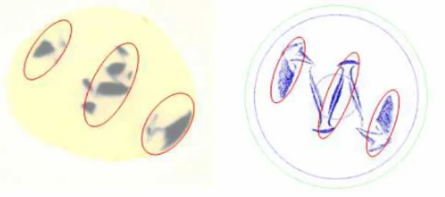
Figure 3 compares the effect of the flow in the die on the blend morphologies for systems 2 and 3.
Figure 3: Morphology at the die exit for systems 2(a) and 3(b)
It appears clearly that viscosity ratio has an important impact on the ability of the dispersed phase to be deformed and elongated. The structures for the low viscosity ratio (system 2, figure 3a) are much thinner and elongated than for the high viscosity ratio (system 3, figure 3b). This is in accordance with a classical result of the literature, claiming that decreasing viscosity ratio encourages the development of laminar structures (see for example [6]).
3.3 EFFECT OF THE INTERFACIAL TENSION The viscosity ratio of the system 4 is very close to 1. But since the two polymers are different (PE and EVOH), we assume that the interfacial tension is quite different from
the system 1 (with two PE). Figure 4 shows the evolution of the morphology of the system 4.
Figure 4: Evolution of the morphology of the system 4 (4a: after flow in the static mixers, 4b: after flow in the flat die)
We notice, comparing Figures 4 and 2, that the interfacial tension has a great influence on the deformation of the dispersed phase, both during flows in the static mixers and in the flat die. The structures obtained with the system 4 show a more developed lamellar structure than with the system 1.
4
NUMERICAL SIMULATION AND
CONFRONTATION WITH
EXPERIMENTALS RESULTS
The ability to simulate numerically the flow through static mixers and flat dies will not only contribute to give new insights in the mixing flow and the blend morphology evolution, but also provide for a faster and cheaper optimization of the number and the design of the static mixers and of the flat dies, as well as of the process parameters.
Since several years, many studies have been devoted to numerical simulation of flows through static mixers. The main difficulty is to obtain accurate solutions for reasonable computation time, which requires the constant development of new computational techniques or simplifications.
Three-dimensional simulations of the steady laminar flows of polymer in the SMN mixers and the flat die are carried out using the commercial software Polyflow. We adopt the method proposed by Avalosse et al. [7] to predict blend morphology. In our simulations, both polymers have similar physical properties (density, rheological properties) and we assume that there is no interfacial tension.
Figure 5 represents the computed evolution of an initial coextruded structure during the flow through the static mixers and at the die exit.
Figure 5: Computed evolution of the morphology with Polyflow (5a: initial coextruded structure, 5b: after flow in the static mixers, 5c: after flow in the flat die)
The system simulated with Polyflow is similar to system 1 (passive interface, no viscosity ratio). The comparison of figures 2 and 5 shows that the numerical simulation is globally able to predict the morphology and the distribution of the dispersed phase.
In particular, figure 6 compares the computed results with the experimental ones after the static mixers. It shows a rather good agreement, especially to predict the areas where the dispersive phase is absent. Nevertheless, it appears that, whereas the structure obtained with the numerical computation is continuous, it is strongly discontinuous in the experiments.
Figure 6: Confrontation of the experimental results (system 1) with the numerical simulation
5
CONCLUSIONS
It is possible to create different blend morphologies using a coextrusion technique, where two polymers are combined together and then flow through several static mixers and through a flat die. The initial coextruded structure is highly deformed both during the flow in static mixers and in the flat die, leading to different blend morphologies.
Several parameters play a decisive role in those deformations of the dispersed phase: the viscosity ratio and the interfacial tension, as well as the elongation rate (both transverse and parallel to the flow).
The confrontation of these experimental results with numerical simulations presents an encouraging agreement. For further developments, viscosity ratio as well as surface tension will be implemented.
REFERENCES
[1] C. Sollogoub, A. Guinault, M. Pedros. Evolution of coextruded structures in static mixers. In AIP
Conference Proceedings, 10th Esaform Conference on material Forming, pages. 975-979, 2007.
[2] T. Inoue. Morphology of Polymer Blends. In L.A.Utracki, editor, Polymer Blends Handbook, pages 547-576, Kluwe Academic Publishers, 2002. [3] A.M. Sukhadia, A. Datta, D.G. Baird. Mixing
History on the Morphology and Properties of Thermoplastic/LCP Blends. Intern. Polym. Proc., 7:218-228, 1992.
[4] A.G.C. Machiels, K.F.J. Denys, J. Van Dam, A. Posthuma de Boer. Formation, stability, and properties of In-situ composites based on blends of a thermotropic liquid crystalline polymer and a thermoplastic elastomer. Polym. Eng. Sci., 36:2451-2466, 1996.
[5] R.C. Willemse, E.J.J. Ramaker, J. van Dam, A. Posthuma de Boer. Morphology development in immiscible polymer blends: initial blend morphology and phase dimensions. Polymer, 40:6651-6659, 1999.
[6] U. Sundararaj, Y. Dori, C.W. Macoscko. Sheet formation in immiscible polymer blends: model experiments on initial blend morphology. Polymer, 36:1957-1968, 1995.
[7] T. Avalosse, M.J. Crochet. Finite-Element Simulation of Mixing .2. 3-Dimensional Flow-Through a Kenics Mixer. AIChE Journal, 43:588-597, 1997.