HAL Id: hal-01687323
https://hal.archives-ouvertes.fr/hal-01687323
Submitted on 6 Nov 2018
HAL is a multi-disciplinary open access
archive for the deposit and dissemination of
sci-entific research documents, whether they are
pub-lished or not. The documents may come from
teaching and research institutions in France or
abroad, or from public or private research centers.
L’archive ouverte pluridisciplinaire HAL, est
destinée au dépôt et à la diffusion de documents
scientifiques de niveau recherche, publiés ou non,
émanant des établissements d’enseignement et de
recherche français ou étrangers, des laboratoires
publics ou privés.
Thermal behaviour modelling of superplastic forming
tools
Vincent Velay, Thierry Cutard, N. Guegan
To cite this version:
Vincent Velay, Thierry Cutard, N. Guegan. Thermal behaviour modelling of superplastic forming
tools. Materials Science and Engineering Technology / Materialwissenschaft und Werkstofftechnik,
Wiley-VCH Verlag, 2012, 43 (9, SI), pp.799-804. �10.1002/mawe.201200045�. �hal-01687323�
Thermal behaviour modelling of superplastic forming tools
Modellierung des thermischen Verhaltens von superplastischen
Umformwerkzeugen
V. Velay
1, T. Cutard
1, N. Guegan
2High-temperature operational conditions of super plastic forming (SPF) tools induce very com-plex thermo-mechanical loadings responsible to their failure. Various materials can be used to manufacture forming tools: ceramic, refractory castable or heat resistant steel. In this paper, an experimental and numerical analysis is performed in order to characterise the environmental loadings undergone by the tool whatever the considered material. This investigation allows to lead a thermal calculation. It is a preliminary and essential stage to perform the complete thermo-mechanical calculation in order to assess accurate stress levels, or plastic strain occur-ring duoccur-ring the forming process.
Keywords: Forming tools / thermal behaviour / Finite Element simulation / Experiments/
Schl!sselw"rter: Umformwerkzeuge / thermisches Verhalten / Finite Elemente Methode / Versuche/
1 Introduction
Heat resistant cast steels or ceramic materials are currently used to manufacture SPF tools [1, 2]. They allow to form superplasti-cally titanium based sheets. The environmental conditions are severe as the superplastic forming process is carried out at a max-imal temperature close to 900 8C (inside the heating press) and at a minimal temperature depending on the location at the surface of the die close to 200 8C when the mould is pulled out from the heating press to replace the formed component by a new sheet [3]. These thermal cyclic conditions are repeated as many times as necessary to produce the required number of parts to be man-ufactured during one campaign. They induce mechanical stresses and cyclic plasticity that lead to the failure of the die. These mechanisms are very difficult to evaluate from an experi-mental point of view. Numerical simulation seems to be an accu-rate way to reach such information in order to optimise the tool design [4] and to improve its lifetime [5]. So, constitutive models can be developed to reproduce the mechanical behaviour of tools depending on the material used to manufacture the mould [5, 6]. However, the temperature fields have to be first determined pre-cisely during the whole forming process. Indeed, an accurate mechanical behaviour model will not be useful if the thermal gradients within the tool are not well assessed. In this investiga-tion, the thermal environment and behaviour of SPF tools are
investigated for both materials commonly used to manufacture SPF dies: a heat resistant steel and a ceramic material. Two geo-metries combining shapes close to those considered on indus-trial SPF tools are investigated. The first one considers a heat resistant cast steel whereas the second one is manufactured with a fused silica based ceramic material. For both geometries, tem-perature measurements are performed on the one hand on an industrial SPF press furnace and on the other hand on a pilot heating facility dedicated to reproduce the cooling-heating opera-tions occurring in the SPF process and developed at the Research Centre on Tools, Materials and Processes (CROMeP). Moreover, thermal simulations of SPF tools are performed and are then compared with the temperature measurements provided both by the industrial press and the pilot heating facility.
2 Experimental investigation
2.1 Materials and tools
Materials investigated are widely used to manufacture SPF tools: a heat resistant cast steel and a fused silica based ceramic are examined. Thermal properties of both materials are presented in Tables 1 and 2. The densities are not temperature dependant, q = 8200 kg/m3for steel and q = 1940 kg/m3for the brittle
mono-lithic ceramic.
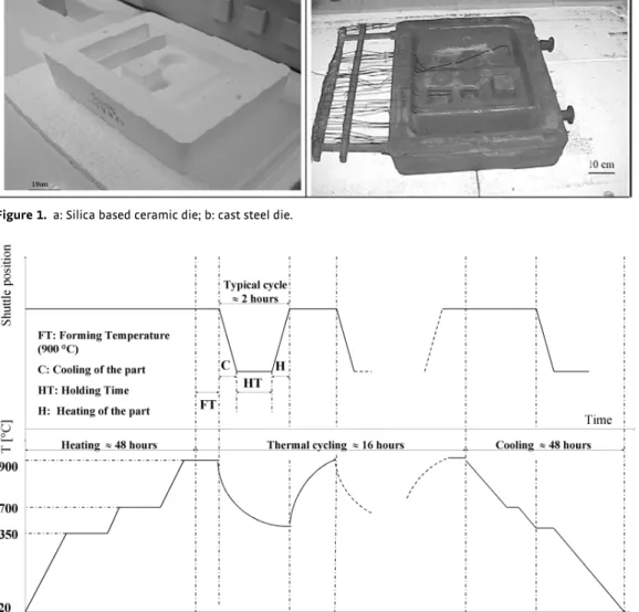
The tool shapes investigated consider severe geometric singu-larities (hole, humps, ramps…) in order to reproduce the ther-mal gradients induced in the industrial dies. Figure 1 presents the fused silica based ceramic (a) and the steel moulds (b).
2.2 Thermal cycles
Thermal cycles typical of the SPF process have been measured on both tools. In situ monitoring of the temperature at the
sur-1Toulouse University – Institut Clement Ader – Mines Albi – Campus
Jarlard, Albi Cedex 09 – France
2Metal Forming Manager – AIRBUS France – Toulouse Cedex 9 –
France
Corresponding author: V. Velay, Toulouse University – Institut Clement Ader – Mines Albi- Campus Jarlard, 81013 Albi Cedex 09 – FRANCE E-mail: [email protected]
face of the tool was performed using K-thermocouples as pre-sented in Figure 1b. Twenty thermocouples were considered for the heat resistant tool and fifteen for the ceramic one. All of them were welded (steel die) or glued (silica die) at the surface of the tools. One of them was located at bottom surface in contact with the heating platen in order to control the temperature ramp dur-ing the heatdur-ing operations. Different test campaigns were per-formed on an industrial SPF press (located in AIRBYS St-Eloi
plant) and also on the CROMeP pilot facility. Thermal cycles investigated are representative to the industrial ones with a cool-ing time between 2 and 10 minutes. Several phases can define a test campaign, Figure 2. The first stage consists in a slow increase of the temperature till 900 8C. The stage 2 includes a temperature stabilisation (FT) followed by the heating press opening to allow the tool pull out and implies a cooling of the part (C + HT). Finally, the die is pushed into the furnace again that induces an increase of the tool surface temperature (H). The stage 2 is repeated as many time as necessary to produce the required number of components. Last, the stage 3 considers the end of the campaign with a slow decrease of the temperature towards the room temperature. The thermal cycles defined in the stage 2 con-sider a heating time around two hours in order to ensure a
ther-Table 1. Thermal properties of heat resistant cast steel.
Temperature [ 8C] 20 100 200 300 400 500 600 700 800 900 1000 Specific Heat Cp [J/kg/K] 415 442 464 481 498 520 561 571 581 595 610 Thermal Conductivity [W/m/K ] 9 11 13 14 16 18 21 23 24 26 28
Table 2. Thermal properties of fused silica based ceramic.
Temperature [ 8C] 20 100 200 500 600 900
Specific Heat Cp [J/kg/K] 737 856 1002 1240 1340 1650
Thermal Conductivity [W/m/K] 0.91 1.05 1.14 1.45 1.54 1.87
Figure 1. a: Silica based ceramic die; b: cast steel die.
mal stabilisation after the furnace charging. This stage is repeated eleven times on the industrial SPF press and twice on the CROMeP heating facility both for the heat resistant steel and for the ceramic mould.
2.3 Results
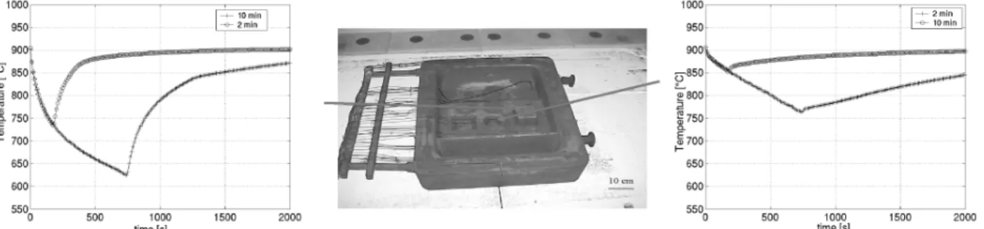
For all campaigns, the heating plates were fixed to a temperature of 900 8C. The heating time was calculated in order to obtain a temperature gap between the minimal temperature (at the sur-face of the mould) and the maximal temperature (at the bottom) not exceeding 10 8C. The Figure 3 illustrates typical thermal cycles undergone by the cast steel die for different cooling times between 2 and 10 minutes. Two thermocouple locations are examined. The first one considers the temperature field moni-tored in a hole and the second one monimoni-tored in a hump. In this last case, a minimal temperature around 550 8C is reached for a cooling time of 10 min whereas a minimal temperature around 700 8C is provided by the thermocouple welded in the hole. Fig-ure 3 concerns thermal tests performed on the industrial SPF press. Several cycles were performed, a cyclic stabilisation was observed. Moreover, the same experimental campaign was con-ducted twice and a good repeatability was obtained whatever the considered tool. These tests were also conducted on the CROMeP heating facility. Figure 4 shows a comparison of the thermal cycles provided by the two devices set up at the same location, for the ceramic mould and two cooling times (2 and 10 min). A good correlation between the two cycles can be noticed for the cooling operation. However, some differences were observed during the heating phase with a temperature rate provided by the CROMeP
heating facility more important as illustrated in Figure 4. Indeed, the thermal environment is not exactly the same for both devices, so that the thermal gradient induced into the tool is less impor-tant in the case of the industrial press.
Whatever the locations investigated at the surface of the metal-lic or ceramic tools, the same conclusions can be formulated. These experimental thermal cycles allow to characterize the ther-mal environment of SPF dies and to validate a Finite Element model able to assess the cyclic thermal gradients induced in the moulds and responsible for the tool damage.
3 Thermal calculation
3.1 Modelling
Both geometries were meshed with linear tetrahedron element types. As the global size of the metallic tool is twice as important, Finite Element models generated consider about 102 000 degrees of freedom (dof) for the metallic mould and 75 000 dof for the ceramic die. Figure 5 shows the Finite Element meshes of the metallic and ceramic tools.
The heat transfer analysis is performed with ABAQUSm soft-ware. It combines conduction, convection and radiation to describe the different stages of the SPF process. Equation 1 is considered to perform an uncoupled heat transfer analysis: Z V qCp dT dt dV ¼ " Z V kDTdV þ Z V rdV ð1Þ
where q, k and Cpare the thermal material properties presented
in the previous section. T is the temperature field, V is the
Figure 3.Thermal cycles at different locations at the surface of the tool for several cooling times.
Figure 4. Comparison of the thermal cycles provided by the industrial SPF press (dot lines) and those obtained with the CROMeP heating facility (continuous lines) in the case of the ceramic die).
volume of the tool and r is the heat supplied externally into the body per unit volume. Several thermal boundary conditions have to be considered. First, in order to reproduce the heating opera-tion, prescribed temperature T is specified on the surface of the tool in contact with the lower heating platen whose value is provi-ded by the thermocouple welprovi-ded at this location. Second, prescri-bed surface heat flux allows to consider surface convection and to take into account the cooling of the part, it can be described by equation 2:
q ¼ hðT " TvÞ4 ð2Þ where h is the film coefficient and T/the sink temperature. Last,
surface radiation was taken into account by equation 3 in order to describe the heat losses during the cooling phase and the tem-perature increase during the heating phase:
q ¼ AððT " TZÞ4" ðT " TvÞ4Þ ð3Þ where A the constant radiation (emissivity times the Stefan-Boltzmann constant) and TZ is the absolute zero. An initial tem-perature equals to 900 8C was considered for all the simulations. So only stationary calculation is considered and thermal cycles are assumed to be stabilized. Moreover, the first temperature increase at the beginning of the SPF campaign and the last decrease at the end were not investigated.
3.2 Results
Emissivity of metallic material was considered as equal to 0.82 and to 0.5 for the ceramic one. The sink temperature was selected to be 25 8C corresponding to the ambient temperature during the cooling stage and 900 8C during the heating stage corresponding to the hearth temperature. Moreover, experimental thermal
cycles allow to determine an uniform film coefficient at the sur-face of the tools close to h = 5W/m2/K. For the radiation
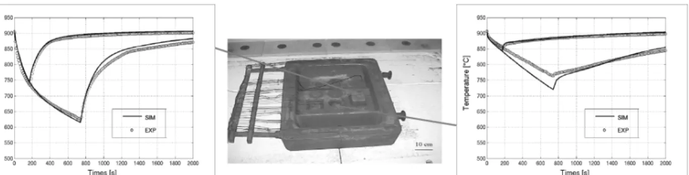
condi-tions, a sink temperature of 25 8C is considered for the cooling phase and 900 8C for the heating stage. Last, temperature evolu-tion monitored by the thermocouple welded on the surface in contact with the bottom was applied to simulate the thermal loading/unloading. Figure 6 illustrates a comparison between experimental and calculated thermal cycles at different locations at the surface of the metallic mould.
Same agreements between experimental and numerical responses are obtained for the other locations at the surface of the tool. Moreover, the same investigation conducted on the ceramic mould leads to the same conclusions, Figure 7.
Figure 8 presents the temperature maps for both forming tools at the end of the cooling (10 min). It is obvious that the maximal temperature is obtained at the lower surface of the mould, sur-face in contact with the heating platen, whereas the minimal temperature occurs at the upper surface specifically in the cor-ners of the die and on the hump. A maximal temperature change of 225 8C between the hottest and coldest conditions is calculated. Same observations can be formulated for the ceramic tool, but the maximal temperature change increases up to 550 8C. Repeated thermal loadings induce a cyclic plasticity (metallic mould) and high stress levels (ceramic mould) responsible for the tool damage.
In order to reproduce the thermo-mechanical loading of SPF dies, it is quite necessary to well assess the thermal gradient induced into the tools during the forming process. Otherwise the thermo-mechanical calculation will not be efficient to obtain accurate strain and stress levels even if the mechanical model used to describe the material behaviour (metallic or ceramic) is relevant. This was the main objective of this study. Hence, the next part proposes an example of thermo-mechanical calculation that intends to reproduce the complete super plastic forming cycle.
4 Thermomechanical analysis
In this part, only the heat resistant cast steel is investigated. The mechanical approach used to reproduce the material behaviour was investigated in the PhD work of Martinier [7]. A viscoplastic model is used. It is able to take into account strain rate and dwell time effects that becomes very important at high temperature.
Figure 5. Finite Element meshes of the metallic (a) and ceramic (b) tools.
Figure 6. Comparison of experimental and calculated thermal cycles for two different locations at the surface of the metallic mould (hole and hump).
This model was implemented in ABAQUS software using Z-mat library [8]. An uncoupled Finite Element simulation is consid-ered, it consists in reading the temperature map provided by the pure thermal simulation. Thus, an example of a complete Super Plastic Forming cycle can be simulated. First, an initial temper-ature of 900 8C is considered into the tool (isothermal steady state). Moreover, the floor that supports the die is considered to be a rigid surface. Then, the calculation can be divided into 5 different stages:
– stage 1 (4s): a pressure of 2 MPa is applied on the edges of the upper surface, it reproduces the clamping pressure of the sheet
– stage 2 (3600s): the forming pressure is applied on the whole upper surface to simulate the sheet forming
– stage3 (4s): all pressures are released
– stage 4: the mould is pulled out from the heating press, it cor-responds to the cooling phase
– stage 5: the mould is pushed into the press again to form a new component.
Stages 1 to 5 illustrate a complete SPF cycle. The simulation of the first forming cycle was performed, it allows to conclude that a slight plasticity occurs during the clamping pressure application (Stages 1 to 3). But the maximal plasticity and stress concentra-tions occur at the end of the cooling phase. So, stage 4 seems to be the most damaging step of the forming process cycle. Figure 9 illustrates the von Mises stress and equivalent plastic strain maps at the end of the cooling stage (2 min). Then, the critical locations where the tool could be preferentially cracked can be determined.
This methodology can be applied to perform design optimisa-tion of industrial dies. It would consist in modifying the shape in order to reduce the cyclic plasticity and the stress concentrations in the tool and consequently would allow to increase the lifetime.
5 Conclusions
A methodology to describe the thermal behaviour of SPF dies was developed. It considers two materials used to manufacture SPF tools. It includes a complete experimental investigation pro-viding in-situ temperature measurements at different locations on the surface of the moulds. Two main experimental campaigns
Figure 7. Comparison of experimental and calculated thermal cycles for two different locations at the surface of the ceramic mould (hole and hump).
Figure 8. Calculated temperature fields at the end of the cooling operation: (a) steel and (b) ceramic moulds.
were conducted, on an industrial press and on a laboratory heat-ing facility. It allows to validate the different parameters required by the numerical simulation (film coefficient, sink temperatures, emissivity…). This work is an important preliminary stage before performing the thermo-mechanical calculation of a com-plete Super Plastic Forming cycle. One example is given for a heat resistant cast steel mould. A mechanical model developed in non isothermal conditions [7] was used to run the Finite Ele-ment simulation. So, the critical locations can be assessed in terms of cyclic plasticity or stress concentration. This approach can constitute an efficient numerical way to optimise the mould design in order to increase its lifetime.
Acknowledgements
Authors gratefully acknowledge E. Jourdain and B. Mottet for their contribution in the experimental and numerical thermal investigations.
6 References
[1] T. Branza, A. Martinier, A. Duchosal, F. Deschaux-Beaume, G. Bernhart, P. Lours, Fatigue Damage and Weld Repair of Heat Resistant Cast Steel SPF Dies. Proceedings of EuroSPF04 – Ecole des Mines d’Albi-Carmaux – France, 2004, 133 – 138.
[2] F. Nazaret, T. Cutard, G. Bernhart, Mechanical Behaviour of Ceramic Materials for SPF Toolings. Proceedings of EuroSPF04 – Ecole des Mines d’Albi – Carmaux – France, 2004, 139 – 144.
[3] S. Baleix, G. Bernhart, P. Lours, Material Science Engineering 2002, A327, 155.
[4] C. Y. Gao, P. Lours, G. Bernhart, Journal of Materials Process-ing and Technology 2005, 169, 281.
[5] G. Luckey Jr., P. Friedman, K. Weinmann, Design and experimental validation of a two-stage superplastic forming die, Journal of Materials Processing and Technology, in Press.
[6] F. Nazaret, H. Marzagui, T. Cutard, Journal of the European Ceramic Society 2006, 26, 1429.
[7] A. Martinier, Dur!e de vie des aciers r!fractaires pour outil-lages SPF: essais et simulations, PhD Thesis ENSMP in french, 2005.
[8] Z-Mat, reference manual, http://www.nwnumerics.com/ Z-mat.