Science Arts & Métiers (SAM)
is an open access repository that collects the work of Arts et Métiers Institute of
Technology researchers and makes it freely available over the web where possible.
This is an author-deposited version published in: https://sam.ensam.eu Handle ID: .http://hdl.handle.net/10985/8695
To cite this version :
Agathe CHOUIPPE, Eric CLIMENT, Dominique LEGENDRE, Céline GABILLET - Numerical simulations of drag modulation by microbubbles in a turbulent Taylor-Couette flow - In: 8th International Conference on Multiphase Flow (ICMF), Korea, Democratic People's Republic Of, 2013-05 - Proceedings of the 8th ICMF - 2013
Numerical simulations of drag modulation by microbubbles in a turbulent Taylor-Couette flow
Agathe Chouippe1,2, Eric Climent1,2, Dominique Legendre1,2 and Céline Gabillet31
University of Toulouse, INPT-UPS, Institut de Mécanique des Fluides de Toulouse, France
2CNRS, IMFT, Institut de Mécanique des Fluides de Toulouse, France 3 IReNav, Institut de Recherche de l’École Navale - Lanvéoc Poulmic, Brest, France
Keywords: Bubbles, Taylor-Couette, Turbulence, Euler-Lagrange simulation, Two-way coupling
Abstract
The aim of our study is to investigate numerically the interaction between a dispersed phase composed of microbubbles and a turbulent Taylor-Couette flow (flow within the gap between two cylinders). We use the Euler-Lagrange approach based on Direct Numerical Simulation of the continuous phase flow equations and a Lagrangian tracking for the dispersed phase. Each bubble trajectory is calculated by integrating the force balance equation accounting for buoyancy, drag, added-mass, pressure gradient, and the lift forces. The numerical method has been adapted in order to take into account the feed-back effect of the dispersed bubbles on the carrying flow. Our approach is based on local volume average of the two-phase Navier-Stokes equations. Local and temporal variations of the bubble concentration and momentum source terms are accounted for in mass and momentum balance equations. A number of reference cases have been tested to validate the modelling approach and its numerical implementation. Then, our previous study of bubble dispersion has been extended to two-way coupling simulations of turbulent Taylor-Couette flows (only inner cylinder is rotating). Modulation of the drag will be discussed for different geometries, Reynolds numbers and bubble sizes. The results show that near-wall turbulent structures are modified by the presence of bubbles.
Introduction
Studying the interaction between a dispersed phase and a continuous one has a wide variety of application, from industrial process engineering to environmental phenomena. Bubble columns, two-phase heat exchangers and bubble entrapment due to breaking waves are such examples. The aim of our study is to focus on the interaction of a dispersed phase composed of microbubbles and a turbulent flow. For that purpose we consider the configuration of the Taylor-Couette device (flow within the gap between two concentric cylinders). This flow configuration has already been investigated experimentally by Wendt (1933), Smith and Townsend (1982), Lathrop et al. (1992), and more recently at high Reynolds numbers by Van Gils et al. (2011a-c, 2012) and Huisman et al. (2012). Direct Numerical Simulations have been carried out for by Dong (2007) and Bilson and Bremhorst (2007), and for Reynolds number up to 30000 by Brauckmann and Eckhardt (2013). Bubbly Taylor-Couette flows have also been experimentally explored by Djeridi et al. (1999) and Djeridi et al. (2004) who focused on the accumulation pattern of the dispersed phase. Dispersion mechanisms have been modelled and numerically investigated by Climent et al. (2007) who proposed a theoretical analysis to predict the migration behaviour of bubbles and a variety of flow regimes. The feed-back modifications induced by the presence of bubbles have been characterized by Mehel et al. (2007) for moderate Reynolds numbers. Modifications of the flow structures due to bubble injection were discussed. In addition to flow structures modification, drag modulation is a key issue for many application related naval transport. For moderate Reynolds numbers, Murai et al. (2008) and Sugiyama et al. (2008) investigated experimentally and numerically the drag
modification due to bubbles. This analysis has been extended to higher turbulent regimes by Van den Berg et al. (2005) and Van Gils et al. (2011a-b).
The aim of our study is to investigate numerically the dispersion of bubbles in turbulent Taylor-Couette flows (Reynolds number ranging from 1000 to 8000) and the possible effects on drag modulation. We are using the finite volume code Jadim with an Euler-Lagrange approach. Our paper is organized as follows: the first section is devoted to a brief description of the numerical method. We will be focusing on the model accounting for the feed-back effect of the bubbles on the carrying phase. We will also detail some test cases which have been considered to validate each physical contribution to the equations and its correct implementation in the code. The second objective of the paper is related to bubble dispersion and flow modifications. Finally, the discussion section summarizes our results in light of studies on bubbly Taylor-Couette flow, but also on bubble drag reduction observed in other geometric configurations (turbulent channel flows, turbulent boundary layers, …)
I - Numerical method
The numerical approach is based on Euler-Lagrange representation: the continuous phase flow is predicted through direct solution of the Navier-Stokes equations while Lagrangian bubble trajectories are computed by numerical integration of momentum balance equation. Modelling the presence of bubbles is based on volume-averaging of the momentum and continuity equations including momentum source terms together with spatial and temporal void fraction variations.
1. Equations for single phase flow
Assuming constant physical properties (viscosity and density), the Navier-Stokes equations (1.1- 1.2) for a Newtonian incompressible fluid are discretized on staggered nonuniform grid with a finite volume approach.
(1.1) (1.2)
Spatial derivatives are calculated with second order accuracy and we use semi-implicit Crank-Nicolson scheme for the viscous term and three steps Runge-Kutta scheme for time integration. The code has already been widely used and validated for laminar and turbulent configurations in single-phase configurations (Climent et al. (2007), Calmet & Magnaudet (2003)).
2. Lagrangian tracking of bubbles
Trajectories are computed through temporal integration of the force balance acting on each bubble (Climent & Magnaudet (1999), and Legendre et al. (1999)).
This balance takes into account buoyancy, drag, added-mass, pressure gradient, and the lift forces (eq 1.3).
v x = dt d (1.3) (1.3) Bubbles are assumed to be spherical while the Weber number is O(10-2). Drag coefficient is then estimated through the correlation of Mei et al. (1994), which gives the evolution of with the Reynolds number of each bubble
(1.4) The added-mass coefficient is . And we used the correlation of Legendre and Magnaudet (1998) for estimating the lift coefficient variation with the bubble Reynolds number and the local shear rate.
Direct bubble/bubble interactions are neglected and bubble/wall overlap is prevented by assuming an elastic bouncing.
The computation of these forces requires the interpolation of the fluid velocity and its time and space derivatives at each bubble location. We used 2nd order accuracy linear interpolation scheme. A second-order Runge-Kutta scheme is used for integrating the force balance in time with a typical time step equal to one fifth of the viscous relaxation time of the bubbles. Loop nesting is used when time steps of both phases are widely separated. When the Eulerian time step (based on numerical stability criteria) is smaller than the Lagrangian characterisitic time then solutions of both sets of equations are synchronized. For large ratio of these time steps , Lagrangian inner loops are integrated in a frozen flow field and the global computing time is dominated by the Lagrangian solver for O(105 to
106) bubbles. Typically, we have
.
3. The Two-Way Coupling model
To account for the action of the dispersed phase on the carrying fluid, we average the Navier-Stokes equations in a control volume of fluid populated by bubbles. The basic principles for this operation can be found in the papers by Ferrante and Elghobashi (2004), or Anderson and Jackson (1967) and Drew (1984). The averaging procedure is based on the function characterizing the presence of the continuous phase locally defined as
(1.5) So, the presence of the dispersed phase can be defined as
.
We also introduce the Dirac function that enables to locate the interface within the volume such as
(1.6)
Figure 1 : Schematic representation of a fluid control volume populated with bubbles, corresponds to the interface between both phases
We introduce then the local volume fraction of the continuous phase (equation 1.7).
(1.7) We can also define the corresponding void fraction
(1.8)
For any given field we introduce its local phase-averaged (equation 1.9).
(1.9) The spatial and temporal derivatives of these local-averaged function has then the following properties
(1.10) (1.11)
We introduce the local-averaged velocity field of the continuous phase
The volume averaging process leads to new continuity (1.12) and (1.13) momentum equations. The influence of the dispersed bubbles on the continuous phase is related to the local evolution of the void fraction, and to the influence of
momentum source term .
(1.12)
(1.13)
(1.14) In those equations, we have neglected momentum transport
by small scale fluctuations (scales smaller than the control volume).We obtained these equations by neglecting this tensor. This contribution would be similar to the Reynolds stress tensor and may have two physical origins: turbulent subgrid scales (unresolved turbulent fluctuations), or bubble induced fluctuations due to finite size effects and direct hydrodynamic interactions. The former can be easily neglected while we intend to perform direct numerical simulations. The latter will be investigated in further studies.
4. Validations
We present now the different configuration tests to validate the implementation of the two-way coupling in our code. First the momentum forcing term itself has been tested without void fraction effects (case 1) , and then the modification of continuity and momentum balance equations due to non uniform (cases 2 to 6).
a) Case 1: Bubble-induced pressure drop
In this first test-case we consider a 3D-channel with stress free boundary conditions on the four boundaries parallel to the mean flow (symmetry conditions) and inflow-outflow conditions in the axial direction. In this case bubbles remain fixed at random positions in the central part of the simulation domain (fig. 2). The dimensions of the
channel are and . The mesh is
regular in x and z directions and non-uniform in y direction
with , We impose a constant
inlet velocity with .
Simulations were unsteady. Pressure is obtained by an iterative solver for the Poisson equation with a convergence criterion of . Fluid characteristics are chosen to lead to negligible viscous dissipation.
Figure 2 : Sketch of the configuration used for the validation in the case 1 whith 40,000 uniform bubbles of radius
In this case we do not consider the effect of the void fraction in the balance equations, yielding:
(1.15) (1.16)
(1.17)
We consider that drag experienced by each bubble is similar which gives:
(1.18) By integrating in the volume of the channel the force balance written in the direction we obtain an analytic expression between the pressure difference, the channel section and the sum of the forcing terms (equation 1.19).
(1.19)
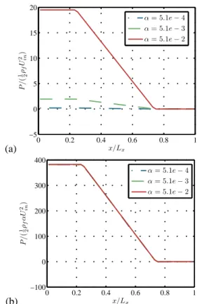
The pressure has a linear evolution across the bubble cloud. While drag force is uniform, the pressure gradient must be proportional to the global void fraction as described by Riboux (2007). This is exactly what we obtained on pressure profiles (figure 3 and table 1). The agreement is very good and validates the implementation of the momentum source term.
(a) 0 0.2 0.4 0.6 0.8 1 −5 0 5 10 15 20 x/Lx P /( 1ρ2 f U 2 in) α = 5.1e − 4 α = 5.1e − 3 α = 5.1e − 2 (b) 0 0.2 0.4 0.6 0.8 1 −100 0 100 200 300 400 x/Lx P /( 1ρ2 f α U 2 in) α = 5.1e − 4 α = 5.1e − 3 α = 5.1e − 2
Figure 3 : Evolution in the direction of the pressure averaged in the channel section, for 3 different void fractions (a) and scaled by the global void fraction (b)
Table 1 : Pressure gradient and relative errors obtained for the different cases considered for the validation of the implementation of the momentum forcing term
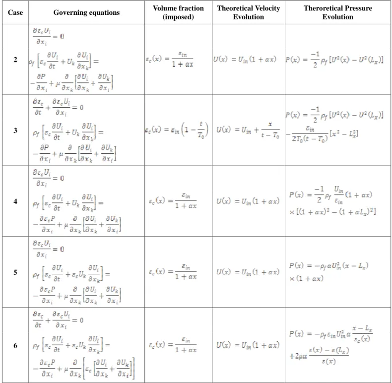
b) Cases 2 to 6: modifications of the Navier-Stokes equations by a non-uniform void fraction
In order to validate the modification of the Navier-Stokes due to the presence of in the balance equations, we have chosen to progressively increase the complexity of tests (summarized in Table 2). For all cases, we proceed as
following: we consider the configuration of case 1 (same mesh, as well) and impose simple variations of , in time or in space. So, velocity and pressure evolutions can be easily predicted by theory and compared to simulations. In cases 2 and 3 we tested the modification of the continuity equation. The aim of case 4 was to validate the modification of the pressure gradient, the modification of the advective term for case 5 and the modification of the viscous contribution to the momentum equation for case 6. For all cases we have .
Case Governing equations Volume fraction
(imposed) Theoretical Velocity Evolution Theroretical Pressure Evolution 2 3 4 5 6
For cases 2 to 5, we neglected the viscous contribution while for case 6 it has been accounted for with . Figure 4 gives the evolutions of the volume fraction of the fluid, the velocity and the pressure. Table 3 summarizes the errors of the computed fields compared to analytic solutions. The error is always below 10-10 for the velocity and O(10-4) for the pressure which validates the numerical implementation.
Case Max relative error for U Max relative error for P Max error for V Max error for W 2 3 4 5 6
Table 3 : Error obtained for the different test validation
5. Conclusion on the numerical method
The effect of fixed bubbles has been successfully tested. It is important to recall that the void fraction is calculated by local summation of the bubble present in a particular Eulerian mesh volume. Void fraction is transported by the Lagrangian motion of the bubbles.
Finally, the code has been parallelized with distinct strategies for the Navier-Stokes solver and for the Lagrangian tracking. Domain decomposition is used for the Navier-Stokes solver thanks to Hallez (2007). Bubble population is equally distributed among all processors involved in the simulation. As it will be presented in the following section, bubbly Taylor-Couette flows are characterized by local accumulation of bubbles. Distributing bubbles based on their position would lead to unbalanced processor load. Therefore, they are distributed based on their index number ranging from 1 to106.
(1)
0 5 10 0.4 0.5 0.6 0.7 0.8 0.9 1 x εc εtheo c case 2 εsimu c case 2 εtheo c case 3 εsimu c case 3 εtheo c case 4 εsimu c case 4 εtheo c case 5 εsimu c case 5 εtheo c case 6 εsimu c case 6 (2) 0 5 10 0 0.01 0.02 0.03 0.04 0.05 0.06 0.07 0.08 x P Ptheocase 2 Psimucase 2 Ptheocase 3 Psimucase 3 Ptheocase 4 Psimucase 4 Ptheocase 5 Psimucase 5 Ptheocase 6 Psimucase 6 (3) 0 5 10 0.1 0.15 0.2 0.25 0.3 0.35 x Ux Utheo x case 2 Usimu x case 2 Utheo x case 3 Usimu x case 3 Utheo x case 4 Usimu x case 4 Utheo x case 5 Usimu x case 5 Utheo x case 6 Usimu x case 6Figure 4 : Summary of the fluid concentration (1), pressure (2) and velocity (3) for the different cases over in the x direction. For case 3 it
corresponds to time .
II - The Taylor-Couette flow configuration
We focus now on the simulation of turbulent Taylor-Couette flow seeded with microbubbles. We consider that only the inner cylinder is rotating and the outer one is kept fixed. The geometry (fig. 5) is characterized by the radius ratio , and the aspect ratio Γ=Lax/(R2-R1) where L is
the length of the domain, R1 and R2 are the radii of the inner and outer cylinders respectively. We use periodic boundary conditions in the axial and azimuthal directions and Dirichlet boundary conditions on cylinder walls. We will consider three radius ratios , and aspect ratios equal to for the two smallest values of η, and for the thin gap.
(2.1) The Reynolds number (eq. 2.1) is defined with the gap width and the velocity of the inner cylinder . This dimensionless quantity which controls the dynamics of the flow for a given geometry is ranging from 1000 to 8000 in our study. For the different radius ratios and Reynolds numbers velocities are normalized by the velocity of the inner cylinder, and lengths by the radius of the outer cylinder.
Figure 5 : Sketch of the Taylor-Couette configuration.
For low Reynolds numbers the flow is purely azimuthal. When increasing we have the TVF regime (Taylor Vortex flow) characterized by the development of large scale toroidal counter-rotating vortices. For larger Reynolds number the Wavy Vortex Flow (WVF) regime occurs followed by Modulated Wavy Vortex Flow (MWVF). At larger Reynolds numbers, the flow becomes turbulent (Turbulent Taylor Vortex Flow, (TTVF), which is characterized by the persistence of the large scale Taylor Vortices and the presence of turbulent fluctuations (fig. 6). For even higher Reynolds number, the Taylor Vortices disappear. We will be considering the TTVF regime. This section is organized as follows: first we describe some
reference results on the single phase flow. Then, we move on the description of “passive” bubble dispersion to highlight accumulation mechanisms possibly leading to drag modulation when two-way coupling is enabled.
1. Single phase TTV flow
The simulations have been validated by comparing statistical quantities to previous studies. The torques acting on cylinders were compared to experimental correlations proposed by Wendt (1933). It is defined by equations (2.1-2.2)
(2.2) (2.3) Our results of the torque are in good agreement with Wendt (1933). More precisely, we simulated the configuration investigated by Dong (2007), corresponding to . Radial evolution of the mean azimuthal velocity
and of the azimuthal velocity fluctuations
were also in good agreement with Dong results. Averages are performed over the axial and azimuthal directions and also over time. The fluctuation is defined by . We observed that the mean velocity profiles were not very sensitive to the spatial discretisation while the fluctuation intensity was used to achieve mesh convergence. The results of our simulations are presented in fig. 7. We observe that a coarse grid leads to an overestimate of the maximum of RMS values. We also compared our results with experimental investigations of Mehel (2006) for the case . Based on those results we selected
appropriate meshes for each case
for the larger gap, for the intermediate gap
and for the smaller one.
Figure 6 : Isosurfaces of the velocity field for , (Left: Instantaneous flow field, right: Mean
velocity field )
In order to characterize the Taylor-Couette flow it is also useful to introduce another average procedure yielding which is only averaged in the azimuthal direction and in time, as proposed by Bilson and Bremhorst (2007). This allows separating the presence of large scale structures (reminiscent of Taylor vortices) and small scale turbulent fluctuations (fig. 6). The decomposition shows the specific contribution of Taylor-Vortices to RMS fluctuation (fig. 7). The presence of these Taylor Vortices induces jet zones: the Inflow and Outflow directed towards and outwards the inner cylinder. Taylor vortices and small scale fluctuations have the same intensity (between to ) for η=0.5. For thinner gaps, the ratio of the Taylor vortices contribution to the small scales contribution is obviously increased .
(1) 0 0.2 0.4 0.6 0.8 1 0 0.2 0.4 0.6 0.8 1 (r − R1)/(R2− R1) < Uθ >x θ t( r ) η = 0.5 η = 0.72 η = 0.91 (2) 0 0.2 0.4 0.6 0.8 1 0 0.05 0.1 0.15 0.2 (r − R1)/(R2− R1) p < (U ′)θ 2> x θ t η = 0.5 η = 0.72 η = 0.91 (3) 0 0.2 0.4 0.6 0.8 1 0 0.05 0.1 0.15 0.2 (r − R1)/(R2− R1) p < (U ′′)θ 2> x θ t η = 0.5 η = 0.72 η = 0.91
Figure 7 :Statistics on the azimuthal component on single-phase flow for and for different radius ratios: (1)
mean field, (2) RMS fluctuations , (3)
RMS fluctuations (((u”θ)2)θt)1/2.
Looking more closely at near-wall turbulent structures, we can see the presence of herringbone-like streaks. They are more intense in the outflow jet zone. These streaks have been numerically studied by Dong (2008), and their structure imposes the local distribution of wall shear stresses (fig. 8). Moreover, an increase of the shear stress is clearly visible in the region of jet impact (either on the inner or outer cylinder). (1) 0 1 2 3 4 5 6 0 0.5 1 1.5 2 θR1/(R2− R1) x / (R 2 − R1 ) 0.5 1 1.5 2 (2) 0 2 4 6 8 10 12 0 1 2 θR1/(R2− R1) x / (R 2 − R1 ) 0 2 4
Figure 8 :Wall shear stresses for and . (1) Inner cylinder, (2) Outer cylinder
We also computed the total shear stress and tested the conservation of the kinetic momentum as: ~ as described by Eckhardt et al. (2007).
(2.4) Two main contributions are present: turbulent friction which dominates in the core region and viscous friction which dominates in the near wall region (fig. 9).
(1) 0 0.2 0.4 0.6 0.8 1 −1.4 −1.2 −1 −0.8 −0.6 −0.4 −0.2 0 (r − R1)/(R2− R1) F ro tt em en t Re = 1000 Turbulent friction Re = 1000 Total friction Re = 3000 Turbulent friction Re = 3000 Total friction Re = 5000 Turbulent friction Re = 5000 Total friction Re = 8000 Turbulent friction Re = 8000 Total friction −R21/r2 (2) 0 0.2 0.4 0.6 0.8 1 −1.4 −1.2 −1 −0.8 −0.6 −0.4 −0.2 0 (r − R1)/(R2− R1) F ro tt em en t Re = 1000 Viscous friction Re = 1000 Total friction Re = 3000 Viscous friction Re = 3000 Total friction Re = 5000 Viscous friction Re = 5000 Total friction Re = 8000 Viscous friction Re = 8000 Total friction −R21/r2
Figure 9 : Different contributions of the global shear for and for different Reynolds numbers: (1) turbulent shear, (2) viscous shear
The pdf of the local friction (fig. 10) is not symmetric (similarly to turbulent channel flows). (1)
−1 0 1 2 3 4 5 10−6 10−4 10−2 100 102 τw/< τw>xθt P (τw /< τw >x θ t ) Re = 1000 Re = 3000 Re = 4000 Re = 5000 Re = 8000 (2) −4 −2 0 2 4 6 8 10 10−6 10−4 10−2 100 102 τw/< τw>xθt P (τw /< τw >x θ t ) Re = 1000 Re = 3000 Re = 4000 Re = 5000 Re = 8000
Figure 10 : Normalized pdf of the wall shear stress for and for different Reynolds numbers: (1) for the inner cylinder, (2) for the outer cylinder
2. Bubble dispersion
Bubbly Taylor Couette flow has been numerically investigated by Climent et al. (2007) for passive dispersion.
They observed accumulation in the Taylor Vortices, which is similar to the experimental evidences of Djeridi et al. (1999). Two dimensionless parameters were defined to characterize the respective contributions of the different migration mechanisms (eq. 2.5 and 2.6).
(2.5) (2.6)
The first parameter (eq. 2.5) depends on the characteristic velocity of the Taylor Vortices and on the terminal rising velocity of the bubbles. This is a measure of force balance in the axial direction: small C values imply that bubbles are not sensitive to the Taylor Vortices and then rise in the domain. On the contrary high C values imply that buoyancy effects are small and bubbles trajectories are strongly affected by the Taylor Vortices (favourable condition for bubble entrapment). H gives an estimate of the relative influence of attraction in the Taylor Vortices in the radial direction (with high H) and centripetal attraction towards the inner cylinder due to added mass effects (typically small H). It is important to recall that H depends only on the flow parameters , while C also depends on bubbles characteristics.
In the literature for higher Reynolds numbers, it has been observed that millimetric bubbles are trapped in the vortices while submillimetric bubbles are trapped near the inner cylinder, in the outflow region (Mehel (2007)). Murai et al. (2008) observed different accumulation patterns: either the formation of collars, or the formation of spirals due to buoyancy effects.
In our simulations the dispersed phase is composed of 106 spherical bubbles, and we considered two bubble radii
, two Reynolds numbers and focused on the larger gap . Bubble positions are randomly seeded in a cylindrical slab located close to the inner cylinder (between
and ). Bubble
velocities are initialized at the local fluid velocity. We obtained bubble accumulation only for the larger bubbles. Bubbles attracted towards the inner cylinder accumulate in the herringbonelike streaks (fig. 11) when buoyancy has a minor effect.
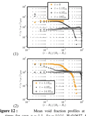
With small bubbles we did not observe any accumulation patterns. Small bubbles are actually much more influenced by small scale turbulent fluctuations and accumulate neither in the Taylor Vortices nor in the outflow region. For large bubbles, accumulation is clear on the mean void fraction profiles (fig. 12) which is peaking near the inner cylinder. Bubble concentration maxima near the inner cylinder have also been experimentally observed by Mehel et al. (2007) and Murai et al. (2008) and numerically by Sugiyama et al. (2008). Such bubble concentration profiles point out the limit of our modelling approach overestimating peak values compared to Mehel et al. (2007) and Murai et al. (2008).
Figure 11 : Bubble positions near the inner cylinder for
the case , , H=0.0637 and
Top: without buoyancy, bottom: with
buoyancy ( ).
Indeed direct bubble interactions (such as collision) may prevent strong accumulation and helps dispersing the bubble by turbulence. As a preliminary conclusion, we can say that bubbles are sensitive to the three major contributions of the Turbulent Taylor Vortex Flow: the primary azimuthal flow induce an important attraction towards the inner cylinder, the Taylor vortices force accumulation (either in vortices or outflow regions), and the small scale turbulent fluctuations enhance local mixing of the dispersed phase. Small bubbles are far more sensitive to these small scale turbulent fluctuations, which leads to an overall uniform distribution of the void fraction.
(1) 10−3 10−2 10−1 100 10−4 10−2 100 102 104 (r − R1)/(R2− R1) < εd >x θ / εglo b t = 0 t = 1.1TΩ1 t = 4.3TΩ1 t = 19TΩ1 (2) 10−3 10−2 10−1 100 10−4 10−2 100 102 (r − R1)/(R2− R1) < εd >x θ / εglo b t = 1.1TΩ1 t = 4.3TΩ1 t = 14.3TΩ1
Figure 12 : Mean void fraction profiles at different
times for case , , H=0.0637, C=∞: (1)
for (2)
It is finally important to notice that bubbly Taylor Couette flow also presents accumulation in the radial direction for high Reynolds number cases (Van Gils et al. (2011b)), but it is difficult to compare our simulations with the high turbulent regime since the structure of the carrier flow is
different than in our simulations.
3. Two-way coupling simulations
We account for the feedback effect of the dispersed phase on the carrying fluid. These aspects have been experimentally investigated by Murai et al. (2008) for Reynolds numbers ranging from 600 to 4500. They obtained noticeable drag reduction due to the presence of bubbles for moderate Reynolds numbers. Sugiyama et al. (2008) numerically investigated the bubbly drag reduction for Reynolds numbers ranging from 600 to 2500. They observed drag reduction when coherent structures of the flow were disorganized by the bubbles. Modifications of the Taylor vortices by the dispersed phase (increase of the axial wavelength of the Taylor cells) have also been experimentally observed by Mehel et al. (2007). Moreover, bubble drag reduction has been experimentally investigated at high Reynolds numbers by Van den Berg et al. (2005) and more recently in the T3C device by Van Gils et al. (2011). For such high Reynolds numbers, deformability of bubbles can play a significant role. Drag reduction has also been investigated in other geometrical configuration, such as Ferrante and Elghobashi (2004) for a spatially developing turbulent boundary layer. Using a modelling approach very much similar to ours, they emphasized role of effective compressibility: bubble migration near the wall induce a non-zero divergence of the flow field which moves the turbulent structures away from the wall, leading to a global friction reduction.
In our study, Weber numbers have been evaluated with the data of the passive bubble dispersion and are typically equal to 10-2. Spherical shape of the bubbles can be safely assumed.
To study two-way coupling, we chose to consider the case with the smallest bubbles. Actually, simulations with large bubbles produced strong numerical instabilities due to strong local accumulation of bubbles in near-wall turbulence structures (a model to prevent bubble overlapping is required for such conditions). Table 4 summarizes the parameters we used. We focus on cases without gravity. Wall units are based on the friction velocity for each wall , the associated viscous length scale and turbulent Reynolds number
. η 0.5 Re 5000 / ( - )/ 1250 0.23 C ∞ H 0.0637 300 150
Table 4 : Parameters of the two-way coupling simulations. The dispersed phase is composed of 106 bubbles, leading to an average void fraction . Simulations with these characteristics did not cause any modification of the carrier flow. By multiplying the forcing terms by a
factor we can reach an average void fraction . Each bubble represents a cluster of 1000 bubbles. This can be acceptable if the number of simulated bubbles is sufficient to statistically describe the dynamics of the dispersed phase.
With this configuration, we obtain some modifications of the structure of the flow (fig. 13) that are similar to observations of Sugiyama et al. (2008) : enhancement of small scale structures and reduce strength of the Taylor vortices.
Figure 13 : Isovalue of the velocity field ( ) after three rotations of the inner cylinder (colors corresponds to the axial velocity, and highlights the presence of the Taylor Vortices). Left: one-way coupling, right: two-way coupling. We did not observe significant modification of the mean velocity profiles. We observe two different transient trends (fig. 14): drag increase on the inner cylinder and drag reduction on the outer one. Such modulation is related to the evolution of the turbulent shear stress (fig. 15) which presents a decrease in the cross-correlation of the fluctuating velocity of the coherent motion as described by Sugiyama et al. (2008). (1) 78 80 82 84 86 4 4.5 5 5.5 6 6.5 7x 10 5 t/TΩ1 G1 Single − Phase T wo − Phase (2) 78 80 82 84 86 4 4.5 5 5.5 6 6.5 7x 10 5 t/TΩ1 G2 Single − Phase T wo − Phase
Figure 14 : Temporal evolution of the torques acting on the inner cylinder (1) and outer cylinder (2). Time is scaled with the one revolution time of the inner cylinder
0 0.2 0.4 0.6 0.8 1 0 0.5 1 1.5 2 2.5 3x 10 −3 (r − R1)/(R2− R1) q < U ′Ur ′ >θ x θ t T wo − Phase Single − Phase
Figure 15 :Comparison of the radial evolution of the mean turbulent shear stress for single and two-phase cases (normalized with the velocity of the inner cylinder). Simulations must be continued to get a definite answer on whether bubbles are reducing or increasing drag in this range of parameters. Nevertheless, similar results to the study of Sugiyama et al. (2008) confirm that the major role of bubble modulation is located in the core of the flow. A possible interaction scenario would be an interaction between bubbles and the inflow-outflow jets. This is still hypothetical at this stage of the work. The study of the single-phase case highlighted that high friction zones correspond to impacting jets. The rotation of the inner cylinder induces an important centripetal attraction towards the inner cylinder. Bubble migration may increase the impact of the inflow jet and decrease the intensity of the outflow, leading to an increase of the inner torque and reduction of the outer torque. Our simulations for single-phase flows showed that the relative influence of the jets tends to decrease with the Reynolds number. Murai et al. (2008) observed crossover between drag reduction and drag increase for Reynolds numbers near from . It would be then interesting to consider other Reynolds numbers, in order to investigate more systematically those interactions.
III - Conclusions and future prospects
We have implemented a numerical approach which enables to compute bubble dispersion with two-way coupling based on Euler-Lagrange approach. The formulation of the influence of the dispersed phase on the continuous one is based on local averaging that modifies the Navier-Stokes equations. The main modifications are the presence of a forcing term in the momentum balance equation and effective compressibility effects.
Our study consists in four contributions: the first one concerns the validation of the feed-back effect on simple configurations. We obtained a very good agreement between computed and analytic solutions. The second part of our study is related to the Taylor-Couette single phase flow. Turbulent Taylor-Couette flow, in the range of considered Reynolds numbers, is composed of three major contributions: a primary azimuthal flow induced by the rotation of the inner cylinder, large scale Taylor Vortices inducing two jet zones, and small scale turbulent fluctuations. The third part of our study deals with the analysis of passive bubble dispersion. We observed that bubble migration is controlled by the three contributions of the flow. The azimuthal flow induces a sustained migration
towards the inner cylinder, the Taylor Vortices may generate accumulation in the axial direction and turbulence damps local accumulation. The last part of our study concerns turbulence modulation induced by bubbles. We noticed a global decrease of turbulent fluctuations located in the core of the flow, a rearrangement of the flow in the near wall region while the mean flow profile remains unchanged. Concerning the drag modulation, we observed different trends for the inner and outer cylinders. In order to conclude more precisely on reduction or increase of drag, it will be necessary to consider other configurations, mainly by changing the global void fraction and the Reynolds number of the flow. Moreover, statistics on two-way coupling simulations need to be further converged.
Acknowledgements
We would like to acknowledge Délégation Générale de l’Armement (DGA) for funding this project. The regional supercomputing centre CALMIP at the University of Toulouse, and the national centres IDRIS and CINES are gratefully acknowledged for their support. We also thank Annaïg Pedrono for her technical support.
References
Anderson T. & Jackson R. “A fluid mechanical description of fluidized beds”, I&EC Fundamental, Vol.6, N°4 (1967) Bilson M. and Bremhorst K., “Direct numerical simulation of turbulent Taylor-Couette flow”, J. Fluid Mech., Vol. 579, p.227-270 (2007)
Brauckmann H.J. and Eckhardt B., “Direct Numerical Simulations of local and global torque in Taylor-Couette flow up to Re=30000”, J. Fluid Mech., Vol. 718, p398 (2013)
Calmet I. & Magnaudet J. “Statistical structure of high-Reynolds number turbulence close to the free surface of an open-channel flow”, J. Fluid Mech, Vol. 474, p. 355 (2003)
Climent E. & Magnaudet J., “Large-Scale simulations of bubble-induced convection in a liquid layer”, Phys. Rev. Lett., Vol. 82, N°24 (1999)
Climent E., Simonnet M., & Magnaudet J. “Preferential accumulation of bubbles in Couette-Taylor flow patterns”, Physics of Fluids, Vol. 19, N°083301 (2007)
Djeridi H., Fave J.F., Fruman D.H., “Bubble capture and migration in Couette-Taylor flow”, Exp. in Fluids, Vol. 26, p.233-239 (1999)
Djeridi H., Gabillet C. and Billard J.Y., “Two-phase Couette-Taylor flow: Arrangement of the dispersed phase and effects on the flow structures”, Phys. Fluids, Vol.16, N°1 (2004)
Dong S., “Direct numerical simulation of turbulent Taylor-Couette flow”, J. Fluid Mech., Vol. 587, p.373-393
(2007)
Dong S., “Herringbone streaks in Taylor-Couette turbulence”, Phys. Rev. E, 77, 035301(R) (2008)
Drew D., “Mathematical modeling of two-phase flow”, Ann. Rev. Fluid Mech., p,264-291, (1984)
Eckhardt B., Grossmann L. and Lohse D., “Torque scaling in turbulent Taylor-Couette flow between independently rotating cylinders”, J. Fluid Mech., Vol. 581, p. 221-250 (2007)
Ferrante A. & Elghobashi S. On the physical mechanisms of drag recution in a spatially developing turbulent boundary layer laden with microbubbles J. Fluid Mech. 503 345-355 (2004)
Hallez Y., “Mélange gravitationnel de fluids en géométrie confine”, PhD Thesis, Institut National Polytechnique de Toulouse (2007)
Huisman G., Van Gils D.P.M, Bruggert G.W., Sun C., Lohse D., “Ultimate Turbulent Taylor-Ciyette Flow”, Phys. Rev. Lett., vol. 108, 024501,(2012)
Lathrop D.P., Fineberg J. and Swinney H.L., “Transition to shear-driven turbulence in Couette-Taylor flow”, Phys. Rev. A, Vol. 46, N°10 (1992)
Legendre D., Colin C., Fabre D. & Magnaudet J. “Influence of gravity upon bubble distribution in a turbulent pipe flow: comparison between numerical simulations and experimental datas”, Journal de Chimie Physique, Vol. 96, N°6, p. 951-957 (1999)
Legendre D. & Magnaudet J. “The lift force on a spherical bubble in a viscous linear shear flow”, J. Fluid Mech, Vol. 368, p.81-126 (1998)
Mehel A., “Etude expérimentale d’un écoulement diphasique de Taylor-Couette”, PhD Thesis, Université de Nantes (2006)
Mehel A., Gabillet C. and Djeridi H., “Analysis of the flow pattern modifications in a bubbly Couette-Taylor flow”, Phys. Fluids, Vol.19 (2007)
Mei R., Klausner F.J. & Lawrence C.J. “A note on the history force on a spherical bubble at finite Reynolds number”, Phys. Fluids, Vol. 6, N°1, p.418-420 (1994) Murai Y., Oiwa H. and Takeda Y., “Frictional drag reduction in bubbly Couette-Taylor flow”, Phys. Fluids, Vol.20 (2008) Riboux G., “Hydrodynamique d’un essaim de bulles en ascension”, PhD Thesis, Institut National Polytechnique Toulouse (2007)
Smith G.P. and Townsend A.A., “Turbulent Couette flow between concentric cylinders at large Taylor numbers”, J. Fluid Mech., Vol. 123, p. 187-217 (1982)
drag reduction in Taylor-Couette flow in the wavy vortex regime”, J. Fluid Mech, Vol.608, p.21-41 (2008)
Van den Berg T.H., Luther S., Lathrop D.P. and Lohse D., “Drag reduction in Bubbly Taylor-Couette turbulence”, Phys. Rev. Letter, Vol.94 (2005)
Van Gils D.P.M., Bruggert G.W., Lathrop D.P., Sun C. and Lohse D., “The Twente turbulent Taylor-Couette (T3C) facility: Strongly turbulent (multiphase) flow between two independently rotating cylinders”, Review of scientific instruments, Vol. 82, (2011a)
Van Gils D.P.M. “Highly Turbulent Taylor-Couette flow”, PhD Thesis, University of Twente (2011b)
Van Gils D.P.M., Huisman S.G., Bruggerts G.W.., Sun C., Lohse D., “Torque Scaling in Turbulent Taylor-Couette Flow with Co and Counterrotating cylinders”, Phys. Rev. Letter, Vol.106, 024502 (2011c)
Van Gils D.P.M., Huisman S.G., Grossmann S., Sun C., Lohse D., “Optimal Taylor-Couette turbulence”, J. Fluid Mech., vol. 706, p.118, (2012)
Wendt F., “Turbulente Strömungen zwischen zwei rotierenden konaxialen Zylinder”, Ingenieur Archiv (1933)