Prototype of a small low noise absolute
displacement sensor
Christophe Collette, Lionel Fueyo-Roza, Mihaita Horodinca
Abstract—Inertial seismic sensors have typically a velocity readout, in order to offer a large dynamic range in a large frequency range. However, in some precision engineering ap-plications, it can be preferable to access to the displacement. An example is the so-called sky-hook spring strategy used for active vibration isolation. In this paper, we present a prototype of small inertial sensor with a displacement readout. It is based on a commercial low cost geophone, which has been modified to measure the displacement with a capacitive sensor. It results in a compact sensor with a resolution which is a factor 10 better than the commercial geophone, but a limited range of amplitudes. The paper finished with an attempt to extend the bandwidth of the sensor at low frequency.
Index Terms—Absolute displacement sensor, geophone, capac-itive sensor, inertial reference.
I. INTRODUCTION
T
HE last fifty years have witnessed tremendous develop-ments in seismometery [1]. Undoubtedly, the cornerstone of this evolution has been the introduction of the so-calledforce balance principle [2]–[5], which reduces the relative
motion between the inertial mass and the support, and provides to feedback seismometers a much larger dynamic range than passive sensors. Actually, the introduction of this balancing force offers many advantages: (1) to increase the linearity of the sensor (because non-linear effects appear for large displacements), (2) to offer a flat sensitivity to acceleration or velocity at low frequency, which is better for measure seismic signals, and finally (3) to use a high resolution capacitive sensor to measure this relative motion. Since several decades, this principle is a standard practice in seismometers. Apart from seismometry, seismometers are also commonly used in Active Vibration Isolation (AVI) systems [6]–[8]. However, for this application, the amplitudes of interest are very small (between 1pm and 100nm), and the quantity of interest can be rather the absolute displacement. To some extend, seismometers, seismic accelerometers and geophones can be used for AVI systems, but further improvements require new developments: reduce the size, decrease the instrumental noise in the frequency range between 0.1 Hz and 50 Hz, increase the robustness to environmental disturbances (e.g. C. Collette and L. Fueyo-Roza are with the Universit´e Libre de Bruxelles, Active Structures Laboratory, 50, av. F.D. Roosevelt, 1050, Brussels, Belgium, e-mail: [email protected].
M. Horodinca is with the Department of Machine-tools and Tools, Faculty of Machines Manufacturing and Industrial Management, Gheorghe Asachi Technical University of Iasi, D. Mangeron 59A, 700050 Iasi, Romania. Copyright c°2012 IEEE. Personal use of this material is permitted. However,
permission to use this material for any other purposes must be obtained from the IEEE by sending a request to [email protected].
Model GS-11D Nunmb. turns/coil 3680 Manufacturer Geospace Wire diameter 0.06mm
Sensitivity 32 V/(m/s) Max current I max 90mA Total weight 0.11 kg Coils out. diam. 27.9mm Inertial mass 0.018 kg Stiffness 24 (N/m) Coils int. diam. 25mm Transducer const./coil 25N/A Corner frequency 4.5 Hz Damping ratio .50
Resistance 2 kΩ
TABLE I
CHARACTERISTICS OF THE GEOPHONE.
stray magnetic field, radiation, temperature variations...), and at an affordable price.
In this paper, we present a prototype of small inertial sensor with a displacement readout, to be used in AVI systems. It is based on a commercial low cost geophone, which has been modified in order to measure the displacement with a capaci-tive sensor. The geophone under test is a GS-11D, Geospace Technologies [9]. Its main properties are summarized in Table I.
The geophone principle is first reviewed in section two. Section three presents the prototype and the experimental results. Section four presents an active mean to extend the bandwidth of the sensor at low frequency. Section five draws the conclusions.
II. GEOPHONE PRINCIPLE
The working principle of the geophone is shown in Fig. 1(a). A coil is encircled around a seismic mass m, and connected to a resistance R. The ground w generates a relative motion between m and the coil. The relative motion creates a current
i, and a voltage V0 across the resistance. The equations of the system are:
m¨x + c( ˙x − ˙w) + k(x − w) + T i = 0 (1) for the mechanical part and
Ldi
dt − T ( ˙x − ˙w) + Ri = 0 (2)
for the electrical part, where i is the current, L is the induc-tance of the coil, and T is the constant of the coil, expressed in (T m) or V /(m/s).
Defining y = x − w, we get in the Laplace domain
ms2Y + csY + kY + T I = −ms2W (3)
LsI − T sY + RI = 0 (4)
The output of the sensor is the voltage V0across the resistance
R, Vo = RI. Assuming that R À sL, the sensitivity of the geophone is given by
Fig. 1. Working principle of (a) a passive geophone and (b) a feedback geophone. Vo sW = −mT s2 ms2+ s(c +T2 R) + k (5) or equivalently, Vo sW = −T s2 s2+ 2ξ0ω 0s + ω02 (6) which is the typical expression of a high pass filter, where
ω0= p
k/m and ξ0= (c +T
2
R)/(2mω0). In a real sensor, V0
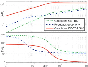
is polluted by several sources of noise, which are essentially characteristics of the mechanical and electrical components of the sensor (Brownian motion of the seismic mass, Johnson noise, current noise,..) [11], [12]. In this paper, all of the noise contributions are lumped in a quantity N . In this case, Equ.(6) becomes V0= S(s)W (s) + N (s) (7) where S(s) = −mT s 3 ms2+ s(c +T2 R) + k (8) is the sensitivity of the geophone expressed in (V /m). Equ.(7) shows that the smallest detectable quantity is limited by the sensor noise N . In practice, N can be measured by combining the output signals of two identical sensors placed side by side [13], [14]. Figure 2 shows the sensitivity curve of the geophone GS-11D, in units of (V/m). Typically, geophones can measure the velocity from a few Hertz to one hundred Hertz. At high frequency, the performances are limited by the higher order modes [10]. At low frequency, the performances are limited by the fundamental resonance of the inertial mass.
Fig. 2. Normalized sensitivity expressed in (V/m) of three sensors: a geophone GS-11D, an absolute displacement sensor (geophone PISECA 510) and a feedback geophone.
Figure 3 shows the power spectral density of the vertical displacement measured on a table in the Active Structures Laboratory at the University of Brussels with the geophone GS-11D, along with the instrumental noise of the GS-11D calculated with two geophones side by side.
Fig. 3. Power spectral density of the vertical displacement measured on a table in the Active Structures Laboratory at the University of Brussels with a geophone GS-11D, with a geophone PISECA 510, instrumental noise of the geophone GS-11D, noise of the capacitive sensor.
One sees from Fig.3 that the noise of the geophone GS-11D is about 10−16 m2/Hz, which is far from the target values presented in the introduction. In the next section, we present a modification of the GS-11D, where a capacitive sensor is mounted to measure the ground motion.
III. CAPACITIVE GEOPHONE
In seismometers, double capacitive sensors are commonly mounted symmetrically around the seismic mass in order to
increase the linearity of the measurement, which is further increased when the measure is used in a feedback loop to restrict the relative motion between the seismic mass and the support. Such arrangement is vital for sub-Hertz applications, where a large dynamic range is required.
A direct measurement of the relative displacement between the casing and the inertial mass may be also useful for several other purposes. For example, it can be used to study the effect of a geophone inclination with respect to the gravitational field. A possible embodiment is disclosed in [15]. In [16], [17] a home made capacitive sensor has been mounted in a GS-11D to develop an affordable feedback accelerometer. In [18], two capacitive sensors are used in a piezoelectric low frequency feedback displacement sensor.
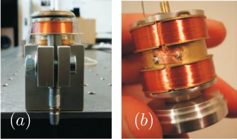
In this study, we measure the displacement of the inertial mass to develop a compact, absolute displacement sensor with a nanometer resolution. The cover of a GS-11D has been removed, and a thin blade has been attached on the middle part of the cylinder which supports the coil. The geophone and a capacitive sensor PISECA 510 from [19] have been mounted on a new dedicated support, shown in Fig. 4(a). The capacitive sensor, further connected to a signal conditioner PISECA E-852 from the same company, measures the relative displacement between the support and the blade, i.e. the inertial mass. For simplicity, it will be called the geophone PISECA 510 in the remaining of this paper. The theoretical sensitivity is shown in Fig. 2. The noise curve of the capacitive sensor is shown for comparison in Fig.3. It has been obtained by recording the signal while the capacitive sensor was pointing a fixed surface. One sees that the resolution of the geophone PISECA 510 is about 10−19 m2/Hz, i.e. ten times as low as the resolution of the geophone GS-11D.
Fig. 4. (a) Geophone PISECA 510; (b) Feedback geophone.
The figure also shows the power spectral density of the vertical displacement measured on a table in the Active Struc-tures Laboratory at the University of Brussels, and recorded at the same time as the geophone GS-11D. One sees that the power spectral densities of the two signals are very similar, even though a small mismatch is visible at very low frequency. The equivalence between the two sensors is confirmed by the excellent coherence between the two signals, shown in Fig.5. In the next section, we investigate a method to further improve the resolution at low frequency, by actively decreasing
Fig. 5. Coherence between the signals recorded by the geophone GS-11D and the signals recorded by the geophone PISECA 510.
the corner frequency of the geophone in order to increase the sensitivity of the inertial sensor at low frequency.
IV. BANDWIDTH EXTENSION
A convenient method to improve the apparent sensitivity of the geophone at low frequency is to use a stretcher filter, with a double pole at ωcand a double zero at ω0, where ωc< ω0[20], [21]. However, if the stretcher increases the bandwidth where the sensitivity is flat, it does not improve the ratio signal/noise of the geophone in the extended frequency range. Instead of the stretcher, consider a feedback geophone as shown in Fig. 1(b), where the coil is divided in two parts. One part is still used as sensor, and the other part is used as an actuator.In this case, Equ.(3) becomes
ms2Y + csY + kY + TaIa+ TsIs= −ms2W (9) where Tsand Ta are the constants of the two parts of the coil.
Using the same assumption that R is large, the output voltage is given by
Vo= RIs' TssY (10)
where Is is the current generated by the relative motion
between the mass and the ground. Then, V0is used to generate a current in the actuator. Taking a classical Proportional plus Integral plus Derivative (PID) controller, we get
Ia= H(s)V0= (gp+gi
s + sgd)V0 (11)
where gp, gi and gd are the gains of the controller. Replacing
(10) and (11) in (9) gives the new sensitivity
Vo sW = −mTss2 (m + TaTsgd)s2+ (c +Ts2 R + TaTsgp)s + k + TaTsgi (12) The corner frequency of the geophone can be actively changed from q k m to q k+TaTsgi
m+TaTsgd by choosing the values gi and gd.
The proportional gain gp is chosen to adjust the damping. In
the useful bandwidth, the sensitivity becomes
Vo sW =
−mTs
m + TaTsgd (13)
and the transfer function between the ground displacement and the relative displacement of the seismic mass is
y
W =
−m
m + TaTsgd (14)
From (13) and (14), one sees that an additional feature of the relative acceleration feedback is that it can modify the sensitivity of the geophone. Choosing a positive value for gd
will force the seismic mass to move with the ground, and reduce the relative displacement of the seismic mass. As a consequence, the sensor will be able to measure much higher levels of vibrations without saturation, which is particularly useful to record strong earthquakes [22]. This is known as the force balance principle. On the other hand, choosing a negative value of gd will increase the sensitivity of the sensor.
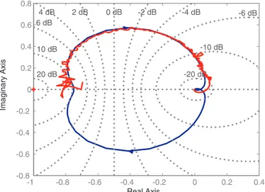
In our case, we are only interested to increase the sensitivity at low frequency. Figure 6 shows the Nyquist plot of the open loop transfer function of the feedback geophone, obtained with the following numerical values: gd = 0; gi = 0.75k; gp =
0.6(c + T2
s/R).
Fig. 6. Theoretical and experimental Nyquist plot of the open loop transfer function of the feedback geophone, obtained with 75% of negative stiffness. The effect of the feedback operation on the sensitivity is shown in Fig. 7. The closed loop sensitivity is also shown in Fig. 2 in units of (V /m) for comparison.
This concept has been tested experimentally. The exterior cover of a second GS-11D was removed, which decreased the transduction constant, and the coil was separated in two independent parts (Fig. 4(b)): the sensor is connected to a dig-ital control system, and the output is connected to the actuator through a current source. The experimental sensitivity curves in open loop and closed loop configuration are compared with the theoretical predictions in Fig. 7.
V. CONCLUSIONS AND PERSPECTIVES
The objective of this study is to develop a new inertial sensor, compact, low cost, and with a sub-nanometer resolution in a frequency range between 1 Hz and 100 Hz. This paper presents a prototype of inertial sensor, being a first step towards this objective. The principle of the geophone has been first reviewed, before presenting the prototype. It consists of a geophone GS-11D in which a capacitive sensor has been
Fig. 7. Comparison of theoretical and experimental open loop (OL) and closed loop (CL) geophone sensitivity.
mounted to measure directly the relative displacement between the support and the seismic mass. It results in an absolute displacement sensor above the fundamental resonance of the seismic mass on the membrane stiffness. The experimental results show that the readout of the new sensor correlates well with the readout of the non-modified geophone, and also that the resolution of the new sensor is improved by more than a factor 10 compared to the non-modified geophone.
Finally, a method has been presented in order to increase actively the sensitivity of the geophone at low frequency. The method has been test experimentally, confirming the theoreti-cal predictions. Nevertheless, additional deep experimentations are still required before making the final decision for any future application of the method.
In a future work, the support of the capacitive sensor will be improved to allow a better alignment. An optical relative sensor is also foreseen as an alternative to the capacitive sensor, which has a limited range, and represents an expensive solution for the poor mechanics of the geophone, especially in regards of its thermal stability, which affects the permanent deflection of the seismic mass.
ACKNOWLEDGMENT
The research leading to these results has been partly funded by the European Commission under the FP7 Research In-frastructures project EuCARD, grant agreement No.227579, and by the Brain Back to Brussels program from Brussels Capital Region for the first author. The authors also gratefully acknowledge the reviewers for their useful comments on the first version of the manuscript.
REFERENCES
[1] C. Collette, S. Janssens, P. Fernandez-Carmona, K. Artoos, M. Guin-chard, C. Hauviller, and A. Preumont, “Review: Inertial sensors for low-frequency seismic vibration measurement,” Bulletin of the Seismological
Society of America, vol. 102, no. 4, pp. 1289–1300, 2012.
[2] H. E. Sheffield, “An electronic vertical long-period seismometer,”
In-strumentation and Measurement, IEEE Transactions on, vol. 13, no. 1,
pp. 2 –7, 1964.
[3] C. Teupser and A. Plesinger, “Design of feedback-controlled wide-band seismographs with respect to undesired side-effects,” Physics of the
[4] E. Wielandt and G. Strekeisen, “The leaf spring seismometer: design and performance,” Bulletin of the Seismological Society of America, vol. 72, no. 6, pp. 2349–2367, 1982.
[5] A. Plesinger, “Analysis and optimization of wide-band force-balance seismometer responses,” Studia Geophysica et Geodaetica, 1984. [6] D. Schubert, A. Beard, S. Shedd, M. Earles Jr., and A. Von Flotow,
“Stiff actuator active vibration isolation system,” United States Patent, Tech. Rep. Patent Number: 5,823,307, 1997.
[7] C. Collette, K. Artoos, A. Kuzmin, S. Janssens, M. Sylte, M. Guinchard, and C. Hauviller, “Active quadrupole stabilization for future linear par-ticle colliders,” Nuclear Instruments and Methods in Physics Research
A, vol. 621, no. 1-3, pp. 71–78, 2010.
[8] C. Collette, S. Janssens, and K. Artoos, “Review of active vibration isolation strategies,” Recent patents on Mechanical engineering, vol. 4, pp. 212–219, 2011.
[9] Geospace, http://www.Geospace.com/.
[10] K. Faber and P. Maxwell, “Geophone spurious frequency: what is it and how does it affect seismic data quality ?” Canadian Journal of
Exploration Geophysics, vol. 33, no. 1, pp. 46–54, 1997.
[11] P. Rodgers, “Self-noise spectra for 34 common electromagnetic seis-mometer/preamplifier pairs,” Bulletin of the Seismological society of
America, vol. 84, no. 1, pp. 222–228, 1994.
[12] G. van der Poel, “An exploration of active hard mount vibration isolation for precision equipment,” Ph.D. dissertation, University of Twente, 2010. [13] A. Brazilai, “Improving a geophone to produce an affordable, broadband
seismometer,” Ph.D. dissertation, Stanford University, January 2000. [14] L. Holcomb, “A direct method for calculating instrument noise levels in
side-by-side seismometer evaluations,” United States Department of the Interior Geological Survey, Tech. Rep. 89-214, 1989.
[15] A. Hagedoorn, “Geophone with mass position sensing, US patent No 2007/0223314 a1,” 2007.
[16] A. Barzilai, T. VanZandt, T. Pike, S. Manionand, and T. Kenny, “Im-proving the performances of a geophone through capacitive position sensing and feedback,” in American Society of Mechanical Engineers
International Congress, 1998.
[17] A. Barzilai, T. VanZandt, and T. Kenny, “Technique for measurement of the noise of a sensor in the presence of large background signals,”
Review of scientific instruments, vol. 69, pp. 2767–2772, 1998.
[18] P. Fraanje, N. Rijnveld, and T. Van den Dool, a vibration sensor and a system to isolate vibrations, WO patent No 2009/139628 A1, 2009. [19] P. I. P. G. . C. P. P. . C. N. P. Sensors,
http://www.physikinstrumente.com/.
[20] L. Zuo, “Element and system design for active and passive vibration isolation,” Ph.D. dissertation, Massachusetts Institute of Technology, Novemeber 2004.
[21] L. Zuo and S. Nayfeh, “An integral sliding control for robust vibration isolation and its implementation,” in Proc. SPIE: Smart Struct. Mater.:
Damping Isol., vol. 5386, 2004, p. 110.
[22] K. Seto, Y. Iwasaki, M. Miyazaki, and A. Ito, “Development of seismometer-type absolute displacement sensor aimed for detecting earthquake waves with large magnitude and long period.” 5th An-nual Dynamic Systems and Control Conference and 11th Motion and Vibration Conference, paper ThBT3.2, 2012.