HAL Id: tel-02466819
https://pastel.archives-ouvertes.fr/tel-02466819v2
Submitted on 6 Feb 2020HAL is a multi-disciplinary open access archive for the deposit and dissemination of sci-entific research documents, whether they are pub-lished or not. The documents may come from teaching and research institutions in France or abroad, or from public or private research centers.
L’archive ouverte pluridisciplinaire HAL, est destinée au dépôt et à la diffusion de documents scientifiques de niveau recherche, publiés ou non, émanant des établissements d’enseignement et de recherche français ou étrangers, des laboratoires publics ou privés.
Experimental and numerical characterization of
functional properties of sand molds produced by
additive manufacturing (3D printing by jet binding) in a
fast foundr
Saptarshee Mitra
To cite this version:
Saptarshee Mitra. Experimental and numerical characterization of functional properties of sand molds produced by additive manufacturing (3D printing by jet binding) in a fast foundr. Other [cond-mat.other]. Ecole nationale supérieure d’arts et métiers - ENSAM, 2019. English. �NNT : 2019ENAM0043�. �tel-02466819v2�
N°: 2009 ENAM XXXX
Arts et Métiers - Campus de Aix-en-Provence Laboratoire MSMP (EA-7350)
2019-ENAM-0043
École doctorale n° 432 : Sciences des Métiers de l’ingénieur
présentée et soutenue publiquement par
Saptarshee MITRA
le 15 novembre 2019Experimental and numerical characterization of functional properties of
sand molds produced by additive manufacturing (3D printing by
binder-jetting) in a fast foundry
Doctorat
T H È S E
pour obtenir le grade de docteur délivré par
l’École Nationale Supérieure d'Arts et Métiers
Spécialité “ Mécanique-matériaux ”
T
H
È
S
E
Directeur de thèse : Mohamed EL MANSORI
Co-encadrement de la thèse : Antonio RODRÍGUEZ DE CASTRO Co-encadrement de la thèse : Marius COSTIN
Jury
M. Michel BELLET, Professeur des Universités, CEMEF, Mines ParisTech Président M. Liam BLUNT, Professeur des Universités, CPT, University of Huddersfield, England Rapporteur M. Jean-Yves HASCOET, Professeur des Universités, GeM, Ecole Centrale Nantes Rapporteur M. Ismail LAZOGLU, Professeur des Universités, MARC, Koc University, Turkey Examinateur M. Mohamed EL MANSORI, Professeur des Universités, MSMP-EA-7350, Arts et Métiers ParisTech Examinateur M. Antonio RODRÍGUEZ DE CASTRO, Maître de Conférences, Arts et Métiers ParisTech Examinateur M. Marius COSTIN, Researcher in NDT, Institute List – CEA Saclay Examinateur
i
Abstract:
Nowadays, traditionally manufactured sand molds and cores for metal casting are being progressively replaced by additively processed sand molds in aerospace/automotive industry, facilitating the production of quality cast parts with complex shapes. The type of additive manufacturing technology used to manufacture 3DP parts in foundries is known as powder-binder-jetting process. In this technology, the molds are produced without the use of any kind of additive tools and in a completely automated way using the layer based construction method. One of the most popular binder systems used in the manufacturing of 3DP mold is a furan-based resin binder, which holds the grain particles together. Their amounts and ratios can influence significantly the 3D printed mold properties, affecting casting quality. Therefore, it is essential to characterize the effects process parameters on the functionality of the 3DP molds. In the present work, the mechanical behavior of 3DP sand molds with varying printing process parameters was first investigated, followed by mass transport properties. To do so, a series of three-point bending strength tests, density measurements, porosity measurements and permeability tests were performed on the 3DP molds. Furthermore, the influence of time, temperature and binder volume fraction on the mechanical and mass transport properties was also investigated. Advanced modelling of the pore space was performed by using the reconstructed images provided by X-ray computed tomography, following different steps: X-ray CT scanning of small 3DP mold specimen, 3D volumetric reconstruction of data, numerical simulations for the prediction of permeability from the reconstructed volume, and pore network modelling for the determination of the pore size distribution. Experiments were also designed to investigate the 3D printed molds in terms of mold erosion during metal casting, in order to select the molding parameters to print 3D printed parts not only with good mechanical and mass transport properties but also to minimize the mold erosion during metal casting. Furthermore, a reverse engineering method for determination of the erosion resistance of sand molds has been established, to study the volume of the eroded surface.
Keywords: Additive manufacturing; Binder jetting; 3D-printed casting sand mold; Casting;
3-Point bending strength; Permeability; Pore Size Distribution; Throat Size Distribution; X-ray tomography; Numerical simulations; Pore network modelling; Mold Erosion; Cast iron;
ii
Résumé:
Les techniques traditionnelles pour la production des moules et des noyaux en sable utilisés en fonderie pour la coulée de métaux sont actuellement en cours de remplacement par des méthodes de fabrication additive, afin d'aider l’industrie aérospatiale/automobile à fabriquer des pièces de forme complexe d'une manière pratique. Le but de ce travail de recherche est d'étudier les propriétés fonctionnelles des moules imprimés en 3D utilisés lors de la coulée des pièces de forme complexe pour des applications d'ingénierie. Premièrement, le comportement mécanique des moules en sables imprimés en 3D a été analysé et caractérisé pour de différents paramètres du processus d'impression. Ensuite, les propriétés mécaniques et de transport de masse des moules en sable 3DP ont été étudiées. Les pièces imprimées en 3D pour la fonderie sont souvent fabriquées avec un type de technologie de fabrication additive appelé « powder-binder-jetting process » (processus de projection de liant de poudre). Des mesures sur trois points de la force de flexion, la densité, la porosité et la perméabilité, ont été effectués sur les moules fabriqués avec la technologie additive. En plus, l’influence de la température et de la fraction volumique du liant sur les propriétés mécaniques et de transport de masse a également été étudiée. Par ailleurs, la perméabilité des moules en sable imprimé a aussi été caractérisée par micro-tomographie de rayons X, permettant la modélisation avancée de la microstructure poreuse en suivant plusieurs étapes : 1) tomodensitométrie de petits échantillons de moules 3DP, 2) reconstruction volumétrique 3D de données, 3) simulation numérique pour la prédiction de la perméabilité à partir de volumes reconstruits et 4) modélisation du réseau de pores pour déterminer la distribution de la taille des pores et des constrictions. Des expériences ont également été conçues pour étudier les moules imprimés en 3D en termes de leur érosion lors de la coulée des métaux. Cela a permis d’identifier les paramètres optimaux du procédé d’impression 3D des moules, non seulement en termes de leurs propriétés mécaniques et de transport de masse, mais aussi pour minimiser l'érosion du moule durant la coulée métallique. Une méthode de détermination de la résistance à l'érosion des moules en sable a également été proposée, sur la base de la mesure du volume de la surface érodée à l'aide d'une technique d'ingénierie inverse moderne.
Mots clés: Fonderie; Fabrication additive; Moules sable impression 3D; Coulée métallique;
Flexion trois points; Perméabilité; Distribution de tailles de grains; Tomographie par rayons X; Simulations numériques; Distribution de tailles de pores; Modélisation réseau de pores; Mold Erosion; Fonte;
iii
“Dedication, hard work all the time, and belief.” – Cristiano Ronaldo
iv
Acknowledgments
Undertaking this PhD has been a truly life-changing experience for me and it would not have been possible to do without the support and guidance that I received from many people. Firstly, I would like to express my sincere gratitude to my thesis director Prof. Mohamed EL MANSORI, and my supervisors, Dr. Antonio RODRÍGUEZ DE CASTRO and Dr. Marius COSTIN for allowing me to conduct this research under their guidance. I am especially grateful for the confidence, motivation and the freedom they gave me to do this work. Their constant encouragement and advice helped me at all the time of research, publiclations and in writing of this thesis, despite their busy agenda. Without a coherent and illuminating instruction, this thesis would not have reached its present form. I could not have imagined having a better advisor and mentor for my Ph.D study.
Besides my advisors, I would like to thank the members of jury: Prof. Michel BELLET, Prof. Liam BLUNT, Prof. Jean-Yves HASCOET and Prof. Ismail LAZOGLU, for accepting to review my manuscript and to participate in the defense of this thesis. I express my gratitude to the members of the jury for their insightful comments and encouragement, but also for the interesting questions which incented me to widen my research from various perspectives. I wish to express my gratitude to Dr. Antonio RODRÍGUEZ DE CASTRO, who helped me to learn techniques in the characterization of gas flow through porous media, during my stay in Laboratory MSMP - Arts et Métiers ParisTech - Châlons-en-Champagne, France. I am also very grateful to Dr. Marius COSTIN who kindly helped me with a great efficiency for the Non-Destructive characterization of 3DP sand mold using X-Ray CT, to extract information at different scales, including micro-scale, during my stay in CEA-LIST - Department of Imaging & Simulation for Non-Destructive Testing - Gif-sur-Yvette, France.
I extend my sincere thanks to all members of the MSMP, and all those who contributed directly or indirectly to the dissertation. I also express my gratitude to all these experts with whom I have had the opportunity to discuss and learn: Dr. Tharmalingam SIVARUPAN, for sharing his expertise in 3D printing technology of sand mold; Dr. Agnès FABRE and Dr. Marie BEDEL, for generously sharing their expertise in teaching students and for their helpful suggestions whenever I had problems during practical sessions for 1st year Engineering students; Mr. Jérémie BOURGEOIS, Mr. Julien NEGRE, and Mr. Wayan GERAUD, for their assistance in the 3D printing of sand specimens and during metal casting operations; Mr.
v Fabrice GUITTONNEAU, for his assistance during the analysis of 3D printed specimens using electron microscope.
I also want to give all my gratitude to my family, and especially to my parents, whose love and support have been a constant motivation. Without their support, I would never finish this thesis and I would never find the courage to overcome all the difficulties during this work. My thanks go to my grandmother Mrs. Manjusree Mitra, my father Capt. Prabir Kumar MITRA, my mother Mrs. Keya MITRA and my brother Mr. Rajarshee MITRA for their confidence and their love during all these years. I would like to extend my warmest thanks and appreciation to my beloved fiancée, Miss. Karima TIBRAYEM. If this work has sometimes prevented us from sharing important moments of life, know that I never stopped thinking about you.
Furthermore, a special thanks to all my doctoral colleagues, Dr. Benjamin GUILLOT, Dr. Hazem MUBARAK, Dr. Hadrien WEIL, Dr. Maxime GELINEAU, Dr. Clément MAUDUIT, Dr. Antonin SANITAS, Dr. François GODET, Dr. Nicolas SPITZ, Mr. Mohamed KBIBOU, Mr. Hugo TRYLA, Mr. Hassan CHOUHAD and Mme. Lisa GERMAIN, who have constantly encouraged me during these years in the laboratory.
Last but not the least, I also wish to thank Mme. Grazyna CAUQUIL, Mme. Laurence COMBARIEU, Mme. Marie FERNANDEZ and Mme. Celine THOMAS for helping me to resolve administrative issues.
vii
TABLE OF CONTENTS
List of Figures………...xi
List of Tables……….……...xvii
1.
GENERAL INTRODUCTION ... 1
1.1 Research Objectives ... 3 1.1.1 Research Question 1: ... 3 1.1.2 Research Question 2 ... 4 1.1.3 Research Question 3: ... 4 1.1.4 Research Question 4: ... 5 1.1.5 Research Question 5: ... 6 1.2 Thesis Roadmap ... 72.
STATE OF ART ... 9
2.1 Casting processes ... 92.2 3D Printing technology in casting applications ... 11
2.3 Powder Binder Jetting (PBJ) ... 13
2.4 Process characteristics and physics involved in the process ... 16
2.4.1 Layering of Powdered Material, Vertical Dimensional Control ... 16
2.4.2 Interaction of a single droplet of binder with the particle ... 16
2.5 Mold fabrication via Powder Binder Jetting technology ... 17
2.5.1 Powder Bed Compaction ... 17
2.5.2 Print-head characteristics ... 18
2.5.3 Binder selection ... 18
2.6 Influence of process parameters on the quality of 3DP molds ... 20
2.6.1 Effect of grains size and shape ... 20
2.6.2 Effect of binder on mold properties ... 21
2.6.3 Effect of curing time ... 23
2.7 Modelling Powder binder jetting process ... 24
3.
EXPERIMENTAL CHARACTERIZATION OF 3DP MOLDS FOR
FOUNDRY PURPOSES ... 25
3.1 Optimum print orientation of 3DP molds ... 25
3.1.1 Introduction and Objective ... 25
viii
3.1.3 Printing Parameters ... 28
3.1.4 Heat treatment and natural curing ... 29
3.1.5 Results ... 30
3.1.5.1 Relative water content ... 30
3.1.5.2 Loss on Ignition ... 30
3.1.5.3 3PB Strength ... 31
3.1.6 Conclusions ... 34
3.2 Effect of curing process parameters on 3DP sand mold ... 34
3.2.1 Introduction and Objective ... 34
3.2.2 Materials ... 35
3.2.3 Design of ageing mechanism experiment ... 36
3.2.4 Printing procedure and parameters ... 36
3.2.5 Curing process ... 41
3.2.6 Density and porosity ... 42
3.2.7 Loss on Ignition (LOI) testing ... 43
3.2.8 Three-point Bending test ... 44
3.2.9 Gas permeability test ... 45
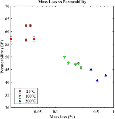
3.2.10 Results ... 46 3.2.10.1 Mass loss ... 46 3.2.10.2 3PB strength ... 47 3.2.10.3 Permeability ... 48 3.2.11 Discussion ... 49 3.2.12 Conclusion ... 53
3.3 Effect of Binder percent on 3DP sand mold ... 54
3.3.1 Introduction and Objective ... 54
3.3.2 Materials ... 55
3.3.3 3D Printing stage ... 55
3.3.4 Curing stages ... 57
3.3.5 Loss on Ignition tests ... 59
3.3.6 Porosity measurements ... 60
3.3.7 Three-Point bending tests ... 61
3.3.8 Permeability tests ... 61
3.3.9 Results and discussion ... 66
3.3.9.1 Evolution of binder content during curing as a function of the initial binder content 66 3.3.9.2 3PB strength as a function of the initial binder content for different curing conditions ... 68
ix 3.3.9.3 Permeability as a function of the initial binder content for different curing
conditions ... 72
3.3.10 Conclusion ... 78
4.
PERMEABILITY CHARACTERIZATION OF 3DP MOLDS USING
X-RAY CT AND ADVANCED POROSITY MODELLING ... 80
4.1 Introduction ... 80
4.2 Scanning Electron Microscope (SEM): General functioning ... 81
4.3 Basic aspects in X-ray micro-computed tomography (X-ray µ-CT)... 82
4.4 Processing reconstructed images ... 84
4.5 Experimental setup ... 86
4.6 Analysis of tomographic images of 3DP mold ... 88
4.6.1 Introduction ... 88
4.6.2 Grain Morphology: Grain Size Distribution (GSD) and Sphericity ... 90
4.6.2.1 Analysis method ... 90
4.6.2.2 Results and discussion ... 94
4.6.3 Direct pore scale modelling ... 96
4.6.3.1 Introduction ... 96
4.6.3.2 Lattice Boltzmann: Theory and Implementation ... 97
4.6.3.3 Calculation of permeability using LBM ... 104
4.6.3.4 Implementation of LBM to predict permeability of 3DP sand mold ... 105
4.6.3.5 Experimental approach: Local porosity and permeability ... 109
4.6.3.6 Results and discussion ... 110
4.6.4 Pore scale modelling with pore network models ... 114
4.6.4.1 Introduction ... 114
4.6.4.2 Chord Length distribution ... 117
4.6.4.3 Pore network extraction from µ-CT images: pore and throat size distributions ... 122
4.6.4.4 Results and discussion ... 125
4.7 Model efficiency ... 132
4.8 Conclussion ... 134
5.
MELT INTERACTION WITH 3DP MOLD SURFACE ... 136
5.1 Introduction ... 136
5.2 Experimental design and Methodology ... 137
5.3 Results and discussion ... 142
5.4 Conclusion ... 148
6.
CONCLUSIONS AND FUTURE PERSPECTIVES ... 149
x
6.2 Conclusion ... 149
6.3 Perspectives ... 150
7.
BIBLIOGRAPHY... 152
xi
List of Figures:
Figure 1 (a) Ancient Greece; bronze statue casting circa 450BC, (b) Iron works in early
Europe: cast-iron cannons from England circa 1543 [4] ... 9
Figure 2. Traditional sand-casting process; (a) Assembled molds, (b) Pouring liquid metal and (c) final solidified casting without the riser... 10
Figure 3. Schematic representation of particle binder bonding and resin ... 13
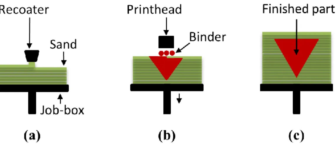
Figure 4. Schematic representation of a 3D printer: (a) lowering the build platform, layering with material and (b) printing process using binder, (c) final part ... 14
Figure 5. Powder binder jetting process ... 15
Figure 6. (a) Simplified model of binder dropping of binder by print-head over powder bed, (b) an SEM image of particle binder bonding along with (c) a schematic representation of interaction of a droplet of binder with the particle. ... 17
Figure 7. Binder categories ... 19
Figure 8. Factors influencing mold properties ... 20
Figure 9. Main Effect Plot of chemically bonded sand mold properties [27]. ... 22
Figure 10. (a,b) The effect of furan resin content with curing time and temperature on tensile strength [66]; (c) Shrinkage and (d) hardness of cores with varying resin content [26]. ... 23
Figure 11. Schematic representation for binder droplet spacing ... 26
Figure 12. Schematic design of parts to be printed over job-box ... 27
Figure 13. Schematic design (a) top view, and (b) side view of the 3DP box with the specimens inside. Each layer has 5 3DP bars with an angle difference of 137.508°; the golden angle ... 28
Figure 14. 3DP Boxes that with the 3PB test bars inside (a,b,c,d), specimens for LOI test (e), 3DP bars printed with an angle difference of 137.508° ... 29
Figure 15. Relative water content over curing time ... 30
Figure 16. Loss on ignition over curing time ... 31
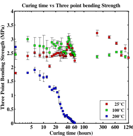
Figure 17. 3PB strength over curing time ... 32
xii
Figure 19. Grain size distribution ... 35
Figure 20. Schematic design of printed specimen on Catia ... 36
Figure 21. Schematic design of a Job-Box (NetFabb) ... 37
Figure 22. 3D sand printer used in the present experiments ... 37
Figure 23. Printing recipe on ExOne 3D printer ... 38
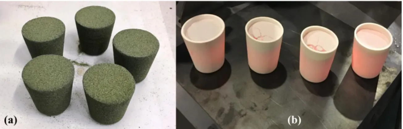
Figure 24. 3D printed 3PB test bars and permeability specimens... 38
Figure 25. Effects of curing temperature and time on the precision of the sand samples ... 40
Figure 26. Precision of the 3D printed samples ... 41
Figure 27. KERN Laboratory precision balance ... 43
Figure 28. Ovens used for accelerated curing ... 43
Figure 29. LOI test crucible with(a) powdered 3DP specimens, (b) immediately after taking out of the oven at 900 °C and (c) after cooling it to 150 °C, before measuring the mass loss 44 Figure 30. Universal strength machine for the 3PB test [78], (a) front view and (b) bar dimensions ... 45
Figure 31. Universal machine used for the gas permeability test[79] ... 46
Figure 32. Critical effect of curing time and temperature on mass loss of specimens ... 47
Figure 33. Critical effect of curing time and temperature on 3PB strength of specimens ... 48
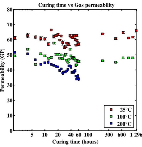
Figure 34. Permeability of the samples vs. curing time at different temperatures ... 49
Figure 35. Furan binder chain reaction ... 49
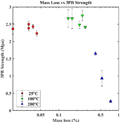
Figure 36. 3PB strength vs. mass loss for the three curing temperatures ... 50
Figure 37. 3PB strength vs. curing time and temperatures ... 51
Figure 38. Permeability vs. mass loss for the three curing temperatures ... 52
Figure 39. Permeability vs. curing time and temperatures ... 53
Figure 40. Scanning electron microscope (SEM) image of the 3DP sample, (a, b) zoom showing the resin bridges ... 57
Figure 41. Samples heat treated inside oven for accelerated curing ... 58
xiii Figure 43. LOI test (a) 3DP samples, (b) immediately after taking out of the oven at 900 °C 60
Figure 44. Perm-meter setup ... 65
Figure 45. Mass loss as a function of curing time for three curing temperatures ... 67
Figure 46. Binder saturation vs porosity of specimens ... 67
Figure 47. Variation of strength with binder, curing temperature and time ... 68
Figure 48. Effect of curing parameters on 3PB strength ... 69
Figure 49. SEM image of 3DP specimen showing resin bridges between particles ... 70
Figure 50. Resin bonding bridge of adjacent sand particles ... 71
Figure 51. SEM image of 3DP specimen showing cracking of resin bridges at 200°C ... 72
Figure 52. Effect of binder content on f vs. Qm rate for uncured samples at 25°C ... 73
Figure 53. Effect of curing time on the relationship between f and Qm at different temperatures and binder contents ... 74
Figure 54. Relationship between apparent permeability and mass flow rate for uncured samples at 25°C ... 76
Figure 55. Evaluation of the inertial effects for uncured samples at 25°C and a binder content of 1.02%: (a) Darcy’s law fit. Black symbols represent experimental measurements. The red dashed line represents Darcy’s law fit; (b) Forchheimer number at different flow rates. ... 77
Figure 56. Variation of permeability with binder, curing temperature and time ... 77
Figure 57. Variation of permeability with binder content, curing temperature and time ... 78
Figure 58. Schematic representation of SEM ... 81
Figure 59. Schematic representation of principle of X-ray tomography ... 82
Figure 60. 3DP specimen ... 83
Figure 61. (a) The projection profile of attenuated X-ray radiography through a 3DP specimen received by the detector and (b) Reconstructed pixel data of 3DP specimen ... 83
Figure 62. Main steps of 3D image reconstruction ... 83
Figure 63. Steps of image processing with Fiji-ImageJ, (a) cropped stack; (b) using median filter; (c) otsu’s thresholding; (d) binary image ... 85
xiv Figure 64. (a) Cross section of raw image; (b) median filtered image of (a); (c) is binary image of (a); (d) is binary image of (b) ... 86 Figure 65. Different views and schemes of the experimental X-ray µ-CT setup showing: (a) the robotic X-ray inspection platform, (b) a schematic design of the sample holder (c) the sample holder and (d) a zoom-in view including the dimensions of the sample ... 87 Figure 66. Grain size distributions and sphericity ... 94 Figure 67. Combined (a) grain size distribution for small grains and big grains, and (b) sphericity distribution ... 95 Figure 68. (a) Examples of silica grain with different sphericity number in the BG specimen. (b) SEM image of a 3DP specimen, showing the silica grains ... 95 Figure 69. Govering equations with LBM ... 97 Figure 70. Streaming before and after propagation in lattice cells ... 99 Figure 71. Diagram showing the velocity discretization in D2Q9 and D3Q19 lattice scheme 99 Figure 72. Images of different dimensions used to determine the Representative Volume Element (RVE) of the BGLB specimen. Pores are displayed in white and silica sand grains in black on the binary image. ... 106 Figure 73. Representative volume element (RVE), for BGLB specimen ... 108 Figure 74. Visualization of steps in conversion of a µ-CT image for velocity distribution simulation in the case of the SGHB specimen (200 voxels): (a) 2D slice of the binary volume and (b) converted image for simulation with pore space (dark blue pixel), grains (yellow pixel) and grain boundary interface (light blue pixel) where the bounce-back boundary condition is implemented. (c) Simulated velocity distribution through a cross-section. ... 109 Figure 75. Velocity map in lattice units through specimens of, (a) 50, (b) 100, (c) 150, and (d) 200 voxel. (Warmer colors represent higher velocity) ... 111 Figure 76. Effect of input geometry volume on the computed value of permeability ... 113 Figure 77. Pores and throats identified by medial axis algorithm ... 116 Figure 78. The clustering of overlapping maximal balls into families, where white arrows indicate the pore–throat chain [133] ... 117 Figure 79. Binary images of the 3DP specimens (SGLB, SGHB, BGLB and BGHB) ... 118
xv
Figure 80. CLD for BGLB specimen ... 119
Figure 81. CLD for BGHB specimen ... 120
Figure 82. CLD for SGLB specimen ... 121
Figure 83. CLD for SGHB specimen ... 122
Figure 84. ALL specimens used for the pore network extraction ... 123
Figure 85. X-ray µ-CT image for all specimens used for PNM ... 124
Figure 86. Extracted pore network for (a) SGLB, (b) SGHB, (c) BGLB and (d) BGHB specimens ... 126
Figure 87. Pore and throat size distribution ... 127
Figure 88. Combined (high binder +low binder) pore size and throat size distribution for (a) small grains and (b) big grains ... 127
Figure 89. Relationship between surface area and volume of all pores in all three samples . 128 Figure 90. Drainage curve ... 130
Figure 91. Throat distribution ... 131
Figure 92. Comparison of permeability for different methods ... 138
Figure 93. Schematic design of mold erosion experiment ... 138
Figure 94. Steps involved, (a) 3D printing of sand mold, (b) melting iron, (c) casting process and (d) eroded molded with the respective positioning of thermocouples... 139
Figure 95. Temperature as noted during casting by thermocouples... 139
Figure 96. Tested slabs as used to study the melt interaction with 3DP sand mold. (a) LB specimen, (b) cleaned LB specimen, (c) HB specimen and (d) cleaned HB specimen ... 140
Figure 97. (a) Thermal deformation testing machine, and (b) zoomed view ... 141
Figure 98. Temperature noted on the back part of testing slab during casting ... 142
Figure 99. Cut section of the testing slabs, (a,b) zoomed view of the side section of interaction ... 143
Figure 100. For LB specimen, (a) laser scanning of testing slabs, (b) cloud data points from scanned data, (c) meshing of cloud data, (d) surface generation and measuring deformation ... 144
xvi Figure 101. For HB specimen, (a) laser scanning of testing slabs, (b) cloud data points from scanned data, (c) meshing of cloud data, (d) surface generation and measuring deformation ... 144 Figure 102. Bar specimens used form thermal deformation testing, (b) zoomed view of LB specimen, and (d) zoomed view of HB specimen ... 146 Figure 103. Temperature as noted for the HB and LB specimens ... 147
xvii
List of Tables:
Table 1. Lists the publication/conference title, incorporated as chapters ... 8
Table 2 The process parameters used for printing the specimens. ... 28
Table 3. Printing process parameters used with ExOne S-Print furan machine... 39
Table 4. Printing process parameters used with ExOne S-Print furan machine... 56
Table 5. Experimental parameters ... 59
Table 6. All results for 3PB strength and permeability ... 74
Table 7. Results showing the pore connectivity and tortuosity ... 93
Table 8. Results from image analysis ... 96
Table 9. Results from permeability simulation ... 112
Table 10. Results from pore network modelling ... 129
Table 11. Results from MIP ... 131
Table 12. Permeability measured with different methods ... 133
Table 13. Results from laser scanned specimens ... 146
1
1.
GENERAL INTRODUCTION
Hybrid casting is an advanced additive mold manufacturing technique, in which the computer model design is integrated with 3D printing in order to fabricate sand molds to produce castings. This offers an excellent opportunity for foundry industries to rethink old/traditional metal casting approaches and to manufacture complex design using computer models. In hybrid casting, the molds are produced without the use of any kind of additive tools and in a completely automated way using the layer-based construction method. The 3D printer generates successive overlaying layers until the full mold is fabricated. The numerous advantages offered by this innovative casting process include a huge reduction in mold manufacturing time and the improved quality of metal castings. Besides, the absence of tooling costs makes this process particularly economical, and much complex geometry that cannot be manufactured using traditional sand casting can be reconsidered. 3D printers are generally faster, easier to use and cheaper than other add-on technologies. It is also possible to make foundry sand molds of extremely small dimensions and very thin parts. Modern foundry industries gradually use this Hybrid Casting technology because they provide ease of sand molding with good surface finish. The furan-based resin is one of the most popular binders used to hold the grain particles together in the manufacturing of 3DP molds. The amounts and ratios of furan binder can influence significantly the 3D printed mold properties resulting in altered casting quality. With rising importance on hybrid casting, there is a need to study and optimize the 3D printing process parameters, which affect the mold properties and have a major impact on the quality of casting.
The present PhD project focuses on the modeling of the 3DP technology to produce functional molds for metal casting in terms of stiffness and permeability. This is expected to assist the aerospace/automotive industry in the selection of the optimum process parameters allowing the minimization of the casting defects. The Low-Pressure-Sand-Casting (LPSC) platform of the Mechanics, Surfaces and Materials Processing (MSMP) laboratory was used to experimentally address these issues. In particular, the ExOne 3DP Machine provided valuable results for the study of the effect of 3DP process parameters (e.g., amount of binder / X-resolution of the Furan droplets, speed of the printer head, and compaction of the mold) on the functionalities of the molds. This work investigates the effects of aging time and temperature on the properties of 3DP at different binder contents, which will facilitate the selection of the optimum binder percent for a given cast product. Also, CEA LIST has several
2 X-ray imaging devices which were used to inspect the 3DP molds in order to find defects or other anomalies. A high-resolution computed tomography scanner was used to characterize small samples, which allowed in extracting structural information (i.e. the grain size and its distribution, porosities of the mold, etc.). The link between the structural properties of the printed molds and the influence of processing parameters, allowed in defining the functional rules for the design of sand molds.
Primary Research Objective
To define functional rules for the design of 3D printed sand molds
The following research works were conducted:
Understanding the effects of the process parameters used during 3D printing on the functionality of the molds (mainly binder content, recoating speed and grain size) and selecting a rigorous experimental method to characterize the mechanical strength and mass transport properties of the 3D printed mold.
Characterizing the mechanical strength and permeability of the 3DP parts produced under different ageing conditions, in order to improve the understanding of the mechanisms controlling the curing stage.
Characterizing the behavior of the 3DP molds through non-destructive volumetric image analysis (X-Ray tomography). Computation of permeability from numerical simulations performed on the obtained 3D digital images and comparison to experimental results.
Studying the processes involved during the interaction of melt with the 3DP sand mold and measuring the volumetric erosion of mold by means of reverse engineering techniques.
3
1.1 Research Objectives 1.1.1 Research Question 1:
The Rapid Prototyping (RP) technology also termed as layered based manufacturing or additive fabrication has become a fast growing and ever-changing family of technologies. Various process parameters are involved in these technologies, such as build direction, printing orientation, recoating speed and binder droplet resolution. For a sand mold to be functional, it is important to consider the application and the direction of the metal casting as, in general, the top (Z axis) or upward facing surfaces of a 3D printed sand mold present better surface finish. Rapid manufacturing of sand molds with PBJ 3D printing consists of 2 major steps: first a fine layer of powder is deposited over the job-box, and then a liquid binds the material according to the desired shape as described on the different slices of the CAD. The same process is repeated until the last layer of the CAD is 3D printed. There exist 2 important steps which highly influence the quality of the functional 3DP sand mold depending on its print orientation. Firstly, the accuracy on the Z axis depends on the defined height of the powdered layer, and thus, which varies slightly from one layer to the other depending on the powder particles, as they are compacted by the recoater. Secondly, the accuracy of the XY axis hinge on the print head (X, Y resolution) movement instrument, which is precise and regular. For these reasons, parts for which the dimensional accuracy is needed should be placed on the XY plane rather than on Z axis. An example of droplet orientation over powder bed is shown in section 3. In order to study the bonding of particles in the powder bed, it was of crucial importance to study the print orientation in the job-box.
Research Objective 1
How does print orientation of molds made from 3D Printed sand molding materials affect their mechanical properties?
This research was designed to classify penetrating materials (furan binder) over powder beds for the ExOne 3D printing machine, as it was crucial to understand the optimum print orientation and to recommend a solution to overcome the above-mentioned issue. Therefore, the sand molds were printed at an angle different from the famous golden or Fibonacci angle (137.508°) with the objective of obtaining less anisotropic properties The optimum build location and orientation of the prototypes being produced by a state-of-the-art ExOne 3D printer installed at MSMP laboratory in Aix-en-Provence was determined.
4 It was found in this research that the parts manufactured using 3DP technologies present anisotropic mechanical properties, which means that they have different properties depending on the printing axis. Usually, the mechanical properties are not as suitable on the Z axis as they are on the X and Y axis. By orientating the part in different directions, there can be a significant difference in the print quality, hence varying mold properties.
1.1.2 Research Question 2
Access to a 3D printer is limited to large scale companies due to its high investment cost. Therefore, 3DP specimens need to be transported to various locations while preserving their original dimensional accuracy. However, safe transportation of the 3D printed parts for direct casting applications or for the characterization of the printed specimens is challenging given their fragile and complex nature.
Once a part is 3D printed, clearing the loose sands on the build platform is time consuming as the printed part should not be damaged while cleaning or during the part removal process from the powder bed. Some researchers need 3D printed specimens with high dimensional accuracy, but deep cleaning of the printed specimens can alter the dimensional accuracy of the part, also affecting the surface properties of the printed specimen.
Research Objective 2
How do 3D Printed sand molds cure within the job-box?
For this reason, a sand mold assembly was printed inside a 3D printed cover and transported straight after printing so that it can cure during transportation. It was found in this research that the sand molds printed inside a 3D printed cover would have similar mechanical properties but with less amount of moisture as compared to the parts 3D printed without a cover, which is an added advantage of curing while storing or transportation of mold assembly from one place to another. This will help the storage or transportation of a 3DP mold specimen for casting application or for the research work with controlled rate of curing, and hence achieving good mechanical properties.
1.1.3 Research Question 3:
Although additive manufacturing of sand molds has enabled designers to commercialize and implement this technology in industry, little is known about the curing behavior of such
5 molds during storage. Knowledge of how the ageing process affects the resulting material properties is critical in the design of the functionality of the molding materials.
Research Objective 3
What is the influence of curing process parameters on the mechanical strength and permeability of 3DP molds?
To do so, the accelerated curing mechanisms were experimentally investigated using a set of 3DP samples produced with chemically-bonded sand used in casting applications. The evolution of the permeability and the three-point bending strength of the samples was monitored over a long time and related to the amount of binder present in the 3DP mold. The experimental results extended our understanding of curing mechanisms and provided rigorous criteria for the choice of ageing parameters.
It was found in this research that 3D printed molds can be stored at room temperature for a long time before being used for casting, roughly preserving the initial properties. Therefore, the objective of the present research work is to study the effects of curing parameters, i.e., curing time and temperature, on the strength and permeability of the 3DP sand molds.
1.1.4 Research Question 4:
As explained earlier, the functional properties of the 3D printed sand mold directly depend on the various printing process parameters, such as the compacting force on the powder bed (by re-coater), the volume and resolution of binder droplet over powder bed in the job-box, and the curing conditions. Many foundries encounter a wide variation in casting properties under uncontrolled conditions within a few hours due to the change in the physical properties of the 3D printed sand mold, e.g., three-point bending (3 PB) strength, gas permeability etc. These properties are further dependent on certain variables - moisture and binder content - which brings about a radical change for the 3D printed specimen. The change in the binder content will affect the 3 PB and permeability. Higher amounts of binder lead to increased strength of 3DP mold, but also to increased gas generation during metal casting and low permeability values. Low permeability values may lead, in turn, to casting defects, including porosities, blow holes, scabbing, and misruns. Consequently, it is necessary to evacuate the gas in an efficient manner in order to obtain a sound casting product with a minimum of defects. For these reasons, the success of this novel technology is strongly conditioned by the production
6 of sufficiently permeable sand molds with convenient mechanical strength for their manipulation.
Research Objective 4
What is the influence of the amount of binder on the mechanical strength and mass transport properties of 3DP molds?
For this reason, the evolution of permeability and mechanical strength of the 3DP sand molds during the curing stage was studied in a recent research work using characterization methods for a unique value of binder content. However, the effects of binder percent on permeability and 3PB strength have still not been studied to the best of our knowledge. Such effects are expected to play a crucial role on the functionality of the casted parts for the above-mentioned reasons. To fill this gap, the present research study focuses on the effect of binder mass fraction on permeability and mechanical strength of printed molds for different curing temperatures and times. It was found in this research that the mechanical strength of the printed 3DP parts/molds is deeply dependent on the amount of binder (change in X resolution) and the curing process.
1.1.5 Research Question 5:
Foundry industries use casting process numerical simulation tools (mold filling and alloy solidification), to improve the yield and to reduce the manufacturing cost before the real time metal casting. However, inaccurate implementation of material physical properties (i.e. local mold porosity, permeability, and strength) reduces the reliability of the numerical results. Non-destructive in situ method like 3D X-ray micro computed tomographic imaging can be used to obtain accurate characterization of 3D printed sand mold specimens (i.e., local microscopic porosity, density, permeability, and strength) as required for casting simulations. Permeability is an important property of 3DP sand mold, which directly affects the casted part quality. Also, porosity, grain size distribution, average grain diameter, pore size distribution, average pore diameter, throat size distribution and average throat diameter are essential inputs when predicting flow in any porous medium, so this is also the case of 3DP molds. Moreover, the 3D images of the pore space provided by X-ray micro computed topography (µ-CT) can also be used for direct numerical computation of multiphase fluid flow and reliably determine permeability.
7
Research Objective 5
How to predict permeability of sand molds through X-ray CT characterization?
X-ray µ-CT is an effective and efficient tool not only to non-destructively visualize the interior of the object, but also to provide the necessary resolution to quantitatively analyze the 3DP sand molds. It was hypothesized that the digital image analysis of sand molds and the numerical simulations using lattice Boltzmann method (LBM) computer simulation and Pore Network Modelling (PNM) could be a reliable alternative (non-destructive testing) to traditional permeability measurements, as they provide more details of the tortuous microstructure.
For this reason, an additional objective of the present work is to study the geometrical and mass transport properties of 3D tomographic reconstructions of samples of 3D printed sand mold using LBM numerical simulations. Also, X-ray µ-CT was combined with LBM to determine the permeability of 3DP sand mold specimen. The resulting values of permeability were then compared with the experimental values and the predicted analytical values. In addition to the LBM simulations, a pore network modelling (PNM) was also performed to extract physically realistic pore network structures from high resolution 3D X-ray CT images of 3DP sand molds.
1.2 Thesis Roadmap
Chapter 1 provides a general introduction of the thesis along with the defined objectives,
followed by Chapter 2 which provides an introduction to additive manufacturing of 3DP sand molds and cores in foundry using powder-binder-jetting technology. The theoretical information of process steps and physical basis of powder binder jetting technology in sand molding was summarized. In Chapter 3, the experimental procedure followed to manufacture the 3DP molds is presented, along with the basis of the proposed methods for characterizing permeability and mechanical strength within a given range of printing process parameters.
Chapter 4 is devoted to a non-destructive characterization of 3DP molds using Micro-focus
X-ray computed tomography (CT) and its application for permeability characterization. Finally, the results presented in Chapters 3 and 4 are used in Chapter 5 to study the erosion phenomena that occurs at the liquid metal-sand mold interface during the metal casting, and experiments are performed to investigate the 3D printed molds in terms of mold erosion related to metal casting.
8 The current thesis integrates material from three papers presented by the author. Chapter 3.2 uses material from References [1] coauthored with Dr. Antonio Rodríguez de Castro and Prof. Mohamed El. Mansori. Meanwhile, Chapter 3.3 is based on Reference [2] coauthored with Dr. Antonio Rodríguez de Castro and Prof. Mohamed El. Mansori. Finally, Chapter 4 is based on Reference [3], coauthored with Prof. Mohamed El. Mansori, Dr. Antonio Rodríguez de Castro, and Dr. Marius Costin. A list of the mentioned works is presented in Table 1.
Table 1. Lists the publication/conference title, incorporated as chapters
Publication Title/Chapter Status Link
The effect of ageing process on three-point bending strength and permeability of 3D printed sand molds (Chapter 3)
Published (2018)
https://dx.doi.org/10.1007/s 00170-018-2024-8
On the rapid manufacturing process of functional 3D printed sand molds (Chapter 3)
Published (2019)
https://dx.doi.org/10.1016/j. jmapro.2019.04.034
Study of the evolution of transport properties induced by additive processing sand mold using X-ray computed tomography (Chapter 4)
Published (2019) https://doi.org/10.1016/j.jm atprotec.2019.116495
On quality assessment of 3D printed sand mold using non-destructive X-ray micro Computed Tomography (µ-CT) -
DIRCT2019
Presented (2019) https://www.dir2019.com/P rogramme#Add.1
9
2.
STATE OF ART
This chapter begins with a bibliographic review of sand casting in foundry, focusing on the traditional technique. Then, the additive manufacturing technology and its use in foundries to print sand molds for metal casting is introduced. Finally, the theoretical and physical basis of powder binder jetting technology underlying the developments in sand molding is summarized.
2.1 Casting processes
Casting is one of the earliest methods for metal shaping in the history of civilization. Archaeological data indicate that the origin of casting process was around 5,000 years ago. Some examples of ancient casting parts are displayed in Fig. 1. These processes consist in pouring a molten metal into a mold (sand or metallic) with a cavity of the shape to be manufactured and allowing it to solidify within the mold. When solidified, the desired metal object is taken out of the mold either by breaking the disposable sand mold or taking the mold apart when a reusable metallic mold is used. The solidified object is called casting. Sand casting is the most widely used metal casting process in manufacturing, and almost all casting metals can casted in sand molds. Sand castings can range in size from very small to extremely large. Some notable examples of items manufactured in modern industry by sand casting processes are engine blocks, machine tool bases, cylinder heads, pump housings, and valves.
Figure 1 (a) Ancient Greece; bronze statue casting circa 450BC, (b) Iron works in early
Europe: cast-iron cannons from England circa 1543 [4]
Modern providers of industrial castings make use of the above-mentioned techniques and improve them based on the understanding of the fundamental principles of fluid flow, heat transfer on molds and casting, thermodynamics and metallurgical microstructural
10 developments. These engineering methods are used to assist the design of casting systems allowing the fabrication of quality metal castings, by minimizing the impact of defects.
Producing a quality metal casting requires a good design effort to:
Create a proper gating system (metal pouring basin, sprue and runner) to let the molten metal flow into the mold cavity free from inclusions and gas bubbles.
Provide a riser which will feed the liquid metal on to the casting cavity as the liquid metal is cooled and solidified (liquid metals shrink when cooling and most liquid metals shrink as they solidify).
Control the heat flow from the mold cavity to the atmosphere so that all significant shrinkage defects are located in the riser.
Figure 2. Traditional sand-casting process; (a) Assembled molds, (b) Pouring liquid metal
and (c) final solidified casting without the riser.
The key to a successful and sound metal casting design is systematic combination of experience and engineering science. The main stages of the designing process are listed below.
i. Design of the part to be cast
Identify the purpose of casting, the shape, the size, the tolerances (manufacturing), by taking into account dimensional change during the casting processes.
ii. Selection of Material for designed Part to be Cast
Mechanical and physical properties of material, including castability, thermal properties and fluid flow properties.
iii. Design and production of the patterns for the molds and cores
Gating system and riser channel design, based on Fluid Mechanics and Heat Transfer concepts.
11
iv. Selection of the casting process
Type of mold (sand or metallic mold), mold size and roughness, mold permeability (for sand molds) and production cost.
v. Post-processing of the casting
Subtractive machining, heat treatment, welding.
vi. Quality control of cast parts
Mechanical and physical properties, destructive or non-destructive testing.
In the system design stage, simulation of the filling and solidification of the proposed part is most valuable. Nowadays, modern computers are commonly combined with powerful software packages to give a preview of mold filling and illustrating the path of solidification. Such simulations are essential to reduce the time between design and prototype castings by avoiding a trial and error approach for the design of both gating system and riser. Although there exist many possible solutions to cast geometries with traditional casting method, the high investment costs in complex parts make 3D printing technology an excellent alternative for the foundry industries, and an opportunity to rethink old casting approaches by using computer models. The Rapid Prototyping (RP) technology, also termed as layered based manufacturing or additive fabrication, is rapidly growing and evolving, and 3D-printed sand molds have been proven to be an effective way for rapid prototyping and manufacturing of sand molds for metal casting. Consequently, 3D printing of complex molds for casting of metals is currently used by different companies like ExOne, 3D Systems, and Viridis3D.
2.2 3D Printing technology in casting applications
Additive Manufacturing (AM), commonly referred as Three-Dimensional Printing (3DP) was invented at MIT as a rapid prototyping technique to build three-dimensional parts directly from computer design model in layers [5–8]. Commercial scale 3D sand printers were invented at Massachusetts Institute of Technology (MIT) to build three-dimensional (3D) parts directly from a computer design model [6,7,9–12]. In 3DP processes, 3D CAD design data are sliced to print up a mold layer upon layer by binding granular material. AM is defined as the process of joining particles from 3D design data to form an object layer upon layer, which is just opposite to subtractive manufacturing. Three-dimensional printing (3DP) of sand molds using binder jetting technology overcomes challenges faced in the traditional production method, e.g., limitations in terms of part complexity and size, production time and
12 cost (which depends on the quantity and the part complexity [13,14], optimization in part design/design freedom for any castable alloys [13–15].
Nowadays, 3DP has become the standard method for the production of molds and cores in the casting industry, with applications in various areas, such as aircraft, automobiles, and medical. This process of rapid prototyping has been widely accepted due to its significant potential to reduce the cost of manufacturing highly complex components [13–15]. Amongst all the rapid tooling and manufacturing processes, 3DP makes the most sense for quick integration into existing industries as it can produce high quality and complex sand molds with the required properties for better casting solutions within a short time frame[16]. Furthermore, the use of binder jetting technique for the production of optimized part designs results in reductions in weight up to 33% compared to the traditional sand mold making process or even any other 3D printing techniques [17].
The layer-based 3DP technology produces porous parts by binding individual particles, which generates permeable molds that are suitable for metal casting despite their lower mechanical strength. And is, therefore, a measure of ease through which the gas generated can flow. It should be noted that molds with excessively high levels of mechanical strength may give rise to hot tearing and high residual stress, which is not convenient for casting [18,19]. In the case of casting molds, ceramics are used as particle materials to provide refractoriness, and a liquid binder is used to ensure cohesion between particles.
Qualitatively, the liquid binder forms capillary bridges between the sand grains as schematically shown in Fig. 3, and the curvature of the liquid interface generates a capillary pressure that causes attraction between grains and high stiffness of the 3D printed parts. This generates a network of sand grains connected by resin bridges hence a complex mold can be printed for metal casting.
The interstices between the grains of sand in the 3D printed parts permit the evacuation of air during the filling of the mold as well as the flow of the gases generated during filling and solidification of the alloy. These gases will be evacuated more or less rapidly depending on the permeability of the sand [20,21]. Good permeability of the mold reduces casting defects formed by trapping of gas pockets within the liquid alloy and subsequently improves the filling ability. While high permeability may lead to metal penetration defect due to large inter-sand grain spacing.
13
Figure 3. Schematic representation of particle binder bonding and resin
The flexural strength of the mold is a function of the grain size, binder content present in the mold and sand compaction [22,23]. Indeed, liquid binder blocks gas flow through the sand, resulting in more gas being trapped during pouring of the alloy leading to gas defects. So, more percentage of binder present leads to more flexural strength and shrinkage but generates excessive gas during casting operations [24–27]. The volume of the gas generated while filling depends on the proportion of the binder however, excessive binder produces too much gas and hence poor quality of the casting[25] and lack of filling [28]. Therefore, it is much necessary to evaluate mechanical and functional 3D printed sand mold properties of the printed mold.
Among various existing binders, organic furan binders are commonly used in foundries for 3DP of sand molds to cast light alloys [18,19,25,28–31]. The main advantage of furan binder is that it cures at room temperature and possesses good mechanical strength[29]. The furan binder condensation reaction produces water, which tends to slow down the rate of curing and hence affects the 3-point bending strength and permeability[32]. Increase in aging time of the 3DP part results in more water being evaporated from specimen.
2.3 Powder Binder Jetting (PBJ)
In this section, an overview of the process of sand binder jetting is provided. Sand additive manufacturing uses the technology of Powder Binder Jetting (PBJ), which constitutes of distinct stages which are repeated continuously to fabricate a 3D component. As compared to other additive manufacturing techniques, PBJ technology presents the particular advantage of not releasing heat during the process of printing, which results in no induced residual stress,
14 and is considered as the standard method for the production of 3DP molds and cores. PBJ process can be used to manufacture large 3DP components and is often more economical or cost-effective than any other existing additive manufacturing technology. Among all processes, the PBJ process is considered the most scalable. A schematic representation of some key stages of the process is shown in Fig. 4.
Figure 4. Schematic representation of a 3D printer: (a) lowering the build platform, layering
with material and (b) printing process using binder, (c) final part
The PBJ process consists of the following steps:
1. Sand is spread over the build platform using an automated roller.
2. The sand bed is then applied with a compacting force by the help of the re-coater. 3. The print head nozzle injects the liquid binding adhesive on top of the sand bed. 4. Binding of sand grains by providing cohesion during drying and curing, Fig 5. 5. The build platform is lowered by the required layer thickness in Z direction. 6. The object is formed where the sand powder is bound to the liquid binding agent. 7. Unbounded sand remains in a position surrounding the printed object.
8. The entire process is repeated until the required object is printed.
A CAD model of the desided part is first created. From the CAD part design, the images are processed sliced into matrix [33] and converted into different formats, such as STL [34] or the recently developed Additive Manufacturing File AMF [35]. While the traditional STL file only deals with the geometry, the AMF file allows the modification of materials and textures [33]. The newly introduced format ASTM AMF file is a massive development for the 3D image processing for additive manufacturing and will be replacing most of the other formats available [35–37]. Unlike its predecessor STL file format, AMF file format has native support for color, textures, materials, lattices, and constellations.
15
Figure 5. Powder binder jetting process
The process of powder binder jetting starts with an empty build platform. At the corner of the job box, the platform is sealed to prevent sand leakage. The recoater then spreads uniform layers of particles on the build platform [7,38]. At the beginning of the printing process, few layers are printed to get an even strong layer of powder bed over which the part will be printed. The print head then moves over the powder and drops binder uniformly onto the layer in X and Y direction. The print head represents a matrix-like arrangement (line of nozzles) and can be accessed over the entire build platform. This line of nozzles corresponds to the driving pattern by print head, as determined by the data model. During the movement of the print head the data updates in rapidly, hence forming the provided image. The print-head uses Drop-on-Demand (DoD) technology, schematized in Fig. 6(a). The binder droplets are formed in the print head due to rapid pressure fluctuations, which are later ejected through a sized nozzle, similarly to the case of ink-jet printing [39]. The binder droplet leaves the micro-nozzle as a free flying droplet. Due to such behavior of droplet, only particular binder material is used [40,41]. Given that the mechanical properties of sand packs mainly depend on the cohesion properties of the binder, the binder liquid should exhibit convenient shear viscosity to fill the interstices without flowing down by gravity. The final step in the printing process is the lowering of the powder build platform in Z direction. After lowering of the power bed build platform (Job-Box), it is once again filled with powdered particles with the help of the recoater. This layer thickness corresponds to the vertical distance the build platform moved while lowering of the powder build platform in Z direction. The entire process characteristics involved during printing will be discussed in the next section.
16
2.4 Process characteristics and physics involved in the process
Most of the features of the 3DP process are related to the nature of the additive process. The rate of the building is restricted by the speed at which the binder can be delivered to the powder bed. In most cases, the amount of solid particles and binder is the same when printing a part. Hence, on a volumetric basis, the part printing rate is limited to twice the flow rate of a binder [8,9]. Past researches have also been conducted to study the steps involved during the process of additive manufacturing.
(a) The layering of powdered material and vertical dimensional control. (b) The interaction of a single droplet of the binder with the particle.
2.4.1 Layering of Powdered Material, Vertical Dimensional Control
After each layer is printed, successive layers are added. The added layer weight produces a compression over the powder bed which leads to loss of vertical dimensional control. Past researchers [6] have proved experimentally, the primary cause for the increase in compression arises from the weight of the sand particles on the powder bed. It was confirmed that the powder bed layer with a higher packing density are more resistant towards vertical dimensional change occurred due to compression of following loading [6]. To control the vertical dimension of the print, a vibratory mechanism was developed, which vibrates the layer of distributed powder to compact the powder in order to gain high packing density [42,43] .
2.4.2 Interaction of a single droplet of binder with the particle
The key parameters for achieving excellent mechanical properties of the Powder Binder Jetting process are directly dependent on the adhesion ability of adjacent sand particles sticking to each other and on the cohesion properties between binder and sand particles. The deposition of the liquid binder droplet over the powdered particle substrate tends to form a new interface between them like wettability, spreading, evolution and adhesion. These forces provide strong bonds between the powdered particles. On the other hand, the wettability of the powder bed by the liquid binder is influenced by the movement of the print-head and the angle at which the binder contacts the powder bed. Therefore, the speed of the print head needs to have the desired rate of movement over the powder bed to suitably drop the binder. As shown in Fig. 6(b) and 6(c), a nearly cylindrical binder bridge is formed between two sand particles, which are modelled as spheres. Under the effect of surface tension, the sand
17 particles bond closer and a strong binder-particle bridge is formed. The solvent used in PBJ process is relatively volatile in nature and tends to evaporate in time, which results in shrinkage of the solid sand skeleton and stronger inter-particle bridges [26].
Figure 6. (a) Simplified model of binder dropping of binder by print-head over powder bed,
(b) an SEM image of particle binder bonding along with (c) a schematic representation of interaction of a droplet of binder with the particle.
2.5 Mold fabrication via Powder Binder Jetting technology 2.5.1 Powder Bed Compaction
Packing density is generally defined as the compactness of a substance. During the preparation of powder bed, the recoater spreads uniform layers of powder on the build platform. Then, each layer is compacted by the recoater to get high packing density of the part. It should be noted that the layers with higher packing density are more resistant towards vertical dimensional change arising from compression of subsequent loadings [6]. Also, the strength and permeability of the printed part are dependent on the compaction density. The packing density of the spherical particles is around 0.60 when un-vibrated and 0.64 when vibrated [44,45]. Apart from the presence of vibration, the critical parameters affecting the packing density are the particle shape, size distribution [46] and also the resin binder content. Indeed, packing density is higher for nearly-spherical particles with regular shape [47], and increases with the sphericity [48] of the particles.
Expendable molds used in casting processes are commonly made from quasi-spherical silica grains. Quartz is the only stable form of silica polymorph at normal ambient conditions, and
18 the density value of α-Quartz (Silica) is known to be 2648 𝑘𝑔𝑚−3. Therefore, the overall density of a given pack of quartz grains can be calculated by multiplying the density value of quartz by (1 - ε), where ε is the global porosity of the type of packing:
- Simple cubic packing = π/6 × 2648 kg m−3 = 1376.96 kg m-3 - Centred cubic packing = π√3/8 × 2648 kg m−3 = 1800.64 kg m-3 - Face-Centred Cubic = π/ 3√2× 2648 kg m−3 = 1959.52 kg m-3
It is reminded here that the theoretical maximum porosity for a simple cubic packing of uniform sand grain size is ε = (1- π/6) and is obtained with a simple cubic packing.
2.5.2 Print-head characteristics
A droplet of the binder is formed only when an electric heat charge is dispersed through the print head and forms a vapor bubble [49]. The mass and the velocity of the binder droplet is a function of the shape and size of the print-head and the physical and chemical composition of the binder [49]. Also, both the firing signal profile and the dimensional stability and accuracy of the orifice, influence the frequency at which binder droplets are generated as well as their volume and velocity [41,49]. During the PBJ process, the number of nozzles is closely proportional to the time required for printing one layer [31]. In this regard, previous works showed that the performance in printing (amount of binder, droplet spacing, etc) is hugely affected by increasing number of nozzles [50].
2.5.3 Binder selection
The binder system plays an important role during the additive manufacturing process of powder binder jetting. Indeed, the strength of the printed part is a function of the amount of binder as well as the thickness of the powdered layer [51].
The binder system must meet several requirements.
a. The binder needs to have excellent bonding properties, to interact with the powder bed
over the build platform (wettability and penetration) and should also have enough strength during the part removal process.
b. The surface tension should be below that of water, which will allow it to spread, and