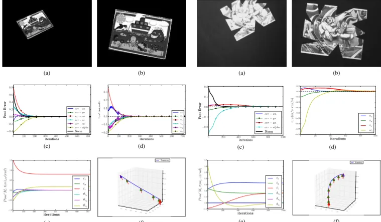
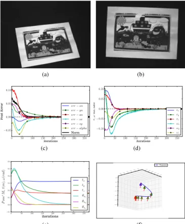
Photometric moments: New promising candidates for visual servoing
Texte intégral
Figure

Documents relatifs
In this paper, a combinatorial method based on Ant System (AS) optimization is proposed in order to minimize the current unbalance factor (CUF) by controlling the connection
L’expression anormale du facteur de transcription appelé stem cell leukemia (SCL) ou T-cell acute leukemia 1 (TAL1) dans le lignage T est l’anomalie la plus récurrente dans
Il semblerait alors que l’un des rôles physiologiques de la protéase NS3/4A dans des cellules infectées soit de prévenir l’induction d’une réponse inflammatoire déclenchée
:صخلملا ىلع نيعتي ، ةيييميلعتلا تاييسسؤملا يف بيوييلا تاييقيبطتل ريييبكلا و رمتسملا ديازتلل ا ًرظن .(مدختسم باسح هيدل) هيلا لوصولا قح هيدل
À l’échelle des neurones, la technique du patch-clamp (Prix Nobel, 1991) permet de comprendre comment les neurones génèrent leurs signaux électriques par une
l’Égypte ancienne a progressivement vu ses spécialistes se replier sur eux-mêmes, prétextant un terrain d’études particulier aux problématiques et méthodes
Dans ce geste qui met entre parenthèses deux aspects fondamentaux de l’ADN (sa mutabilité et sa réplicabilité), Jonas pose l’ADN comme invariant non seulement dans
O objetivo central deste livro é, portanto, divul- gar experiências bem sucedidas de inovação para o desenvolvimento rural. Apesar de uma miríade de casos e atores, o que há em
