HAL Id: hal-03033920
https://hal.archives-ouvertes.fr/hal-03033920
Submitted on 1 Dec 2020HAL is a multi-disciplinary open access archive for the deposit and dissemination of sci-entific research documents, whether they are pub-lished or not. The documents may come from teaching and research institutions in France or abroad, or from public or private research centers.
L’archive ouverte pluridisciplinaire HAL, est destinée au dépôt et à la diffusion de documents scientifiques de niveau recherche, publiés ou non, émanant des établissements d’enseignement et de recherche français ou étrangers, des laboratoires publics ou privés.
Enhancing the thermal performance of vehicle cooling
modules using diffusers - toward energy consumption
and co2 emission reduction
Mahmoud Khaled, Cathy Castelain, Jalal Faraj, Mohamad Ramadan
To cite this version:
Mahmoud Khaled, Cathy Castelain, Jalal Faraj, Mohamad Ramadan. Enhancing the thermal perfor-mance of vehicle cooling modules using diffusers - toward energy consumption and co2 emission reduc-tion. 11th International Conference On Sustainable Energy & Environmental Protection (SEEP18), May 2018, Paisley, United Kingdom. �hal-03033920�
ENHANCING THE THERMAL PERFORMANCE OF VEHICLE COOLING
MODULES USING DIFFUSERS - TOWARD ENERGY CONSUMPTION AND
CO2 EMISSION REDUCTION
M Khaled1, 2, C. Castelain3, J. Faraj1, and M. Ramadan1,4
1. Energy and Thermo-Fluid Group, School of Engineering, International University of Beirut BIU, Beirut–Lebanon
2. University Paris Diderot, Sorbonne Paris Cité, Interdisciplinary Energy Research Institute (PIERI), Paris-France
3. Heat Transfer and Energy Group, Polytech’Nantes, University of Nantes, Nantes–France 4. Associate member at FCLAB, CNRS, Univ. Bourgogne Franche-Comté, Belfort cedex, France
ABSTRACT
In this work, numerical results focused on the enhancement of water-air heat exchanger thermal performance are presented. New designs consisting of using diffusers between the front end openings of the vehicle and the first exchanger facing the airflow are suggested. The diffuser will reduce the velocity magnitude but over a larger area through the exchanger. This will reduce the air velocity non-uniformity upstream the exchanger and then increase its thermal performance. An in-house code is established to evaluate the thermal performance of the exchanger based on known parameters; namely, the ratio of the area of the air inlet opening to the area of the exchanger, the distance between the air inlet opening and the first exchanger at its downstream, the angle of the diffuser, and the water and air mass flow rates. It was shown that the thermal performance of the exchanger can be enhanced by up to 67 % when the diffuser is present depending on the configuration.
Keywords: Diffuser; Energy consumption; Cooling module; Heat exchanger; Thermal performance; Air
velocity uniformity.
1 INTRODUCTION
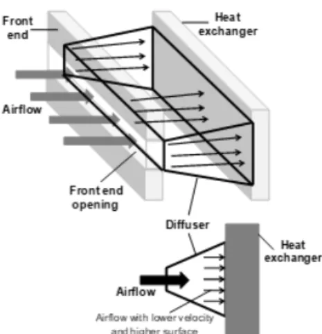
Studies on the effect of air velocity non-uniformity on the thermal performance of liquid-air heat exchangers are present in the literature for different types of heat exchangers and different ranges of applications and operational parameters [1-6]. Particularly, Khaled et al. [7-8] studied the effect of air velocity nonuniformity on the performance of water air heat exchangers of tubes and fins types used mainly in automotive applications. They have concluded that the nonuniformity of air velocity distribution upstream of a tubes-and-fins air-water heat exchanger can decrease its thermal performance up to 35 % when the standard deviation of the distribution is equal to its mean value. From an optimization point of view, the above mentioned conclusion means that to increase the thermal performance of a heat exchanger, the non-uniformity upstream of it should be decreased. This result is the motivation of this work in which a new concept allowing to optimize the thermal performance of water-air heat exchangers is presented. Its main idea consists of using a diffuser between the front end air opening and the first exchanger at its downstream (Figure 1).
Although the use of a diffuser upstream of a heat exchanger will reduce the velocity magnitude upstream the exchanger, the air velocity distribution upstream of the exchanger considered over the entire area of the exchanger will have the same flow rate as at the air inlet opening (the same mean velocity) but with lower standard deviation (or nonuniformity). The decrease of the nonuniformity of the air velocity distribution upstream of the exchanger will increase its thermal performance. To quantify the performance enhancement associated with the use of the diffuser, a parametric analysis that comprises the effect of many parameters will be considered in section 3. These parameters are mainly the ratio of the area of the air inlet opening to the area of the exchanger, the distance between the air inlet opening and the first exchanger at its downstream (which is equal to the length of the diffuser), the angle of the diffuser, and the water and air mass flow rates. Calculations are performed with an in-house computational code that will be presented in section 2.
2 IN-HOUSE COMPUTATIONAL CODE
Details on the code concepts and operational algorithm can be found in [7-9]. Below a short account will be exposed.
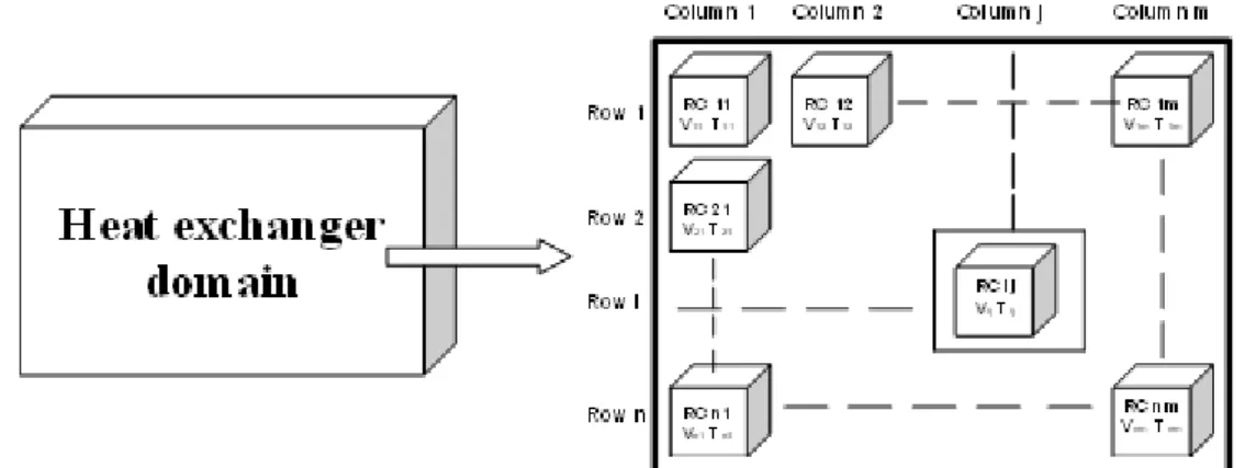
The principle of the method consists in dividing the calculation domain into smaller sub-domains called Representative Cell (RC) representing the different non-uniform conditions that the sub-domains may undergo (Figure 2).
Fig. 2. Division of the heat exchanger domain into sub-domains (representative cells).
The global heat exchanger problem is thus divided into several local problems at each RC. In other terms, the global energy balance problem is converted to several local energy balance problem at each RC. The results of a cell are utilized as boundary condition for the next cell. The temperature at each RC is then calculated and thus the distribution of the temperature is obtained over the entire domain. The outlet temperature of the heat exchanger is calculated from the values of the temperature at the boundary RC of the domain.
The code was validated against experiments and shows very good agreement qualitatively and quantitatively [8].
3 RESULTS, OBERVATION, AND DISCUSSION
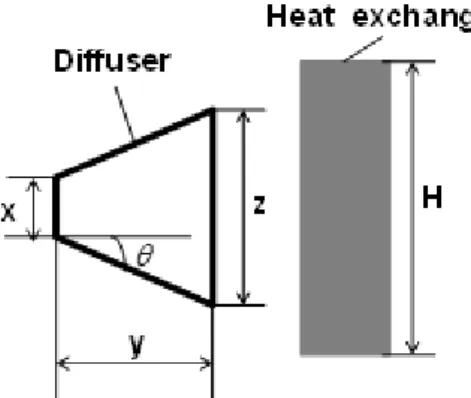
In this section, the aforementioned code is employed to perform parametric study on the thermal performance enhancement of a heat exchanger subjected to the new design integrating a diffuser in the cooling module. Figure 3 shows a schematic of the exchanger and the associated diffuser including the main parameters that will be tested.
Fig. 3. Schematic including the parameters to be tested.
In Figure 3, is the height of the small cross-sectional area of the diffuser (considered equal to front end inlet air openings), is the length of the diffuser in the direction of the flow, is the height of the large cross-sectional area of the diffuser, is the height of the exchanger and is the angle of the diffuser.
The height of the large cross-sectional area of the diffuser is related to the height of the small cross-sectional area by the following relation:
θ tan 2 y x z = + (1)
The different parameters defined above are normalized with respect to the heat exchanger length as follows: H x X = (2) H y Y = (3) H z Z = (4)
Since the height of the large cross-sectional area should not exceed the heat exchanger height, there is a maximum for the length of the diffuser although it will be a sufficient space between the exchanger and front end openings of the vehicle.
Calculations are performed for a water flow rate of 6000 L/h and an air velocity of 7 m/s. The water inlet temperature of water is set at 90 0C and that of air at 20 0C. Ratios of the height of the small cross-sectional area of the diffuser to the HX height of 0.2, 0.3. 0.4, and 0.5 are considered. For each , the ratio of the length of the diffuser to the HX height is varied from 0 to its maximum possible value. The diffuser angle is set equal to 30 0. Figure 4 shows the variation of the HX performance as well as the performance enhancement calculated in each case with respect to the case without diffuser (which corresponds to ) in function of and .
As shown in Figure 4, the thermal performance of the exchanger increases as Y increases and as X increases. On the other hand, the enhancement of the thermal performance increases as Y increases but decreases as X increases. As illustration for X = 0.2 (the air inlet opening corresponds to 20 % of the heat exchanger area), when Y varies from 0 to its maximum of 0.7, the thermal performance of the exchanger increases from 16.3 to 23.1 kW. For X = 0.5, when Y varies from 0 to its maximum of 0.4, the HX thermal performance increases from 39.6 to 79 kW.
Fig. 4. Variation of the (a) HX thermal performance and (b) enhancement in function of X and Y. For X = 0.2, the thermal performance enhancement increases from 0 to 41.9 % when Y increases from 0 to it maximum of 0.7. For X = 0.3, the thermal performance enhancement increases from 0 to 23.8 % when Y varies from 0 to its maximum of 0.4.
4 CLOSURE
This paper suggested a new design for optimizing the performance of a water-air heat exchanger subjected to non-uniform air velocity distribution induced by the geometry of the air inlet openings. The new design consists on using a diffuser between the front end openings of a vehicle and the first exchanger facing the airflow (most commonly the condenser).
It was shown that the thermal performance of the exchanger is enhanced by up to 67 % when the diffuser is present.
REFERENCES
[1] Khaled M., Ramadan M., El Hage H., Elmarakbi A., Harambat F., Peerhossaini H., Review of underhood aerothermal management: towards vehicle simplified models, Applied Thermal Engineering, 73 (2014) 840-856.
[2] Khaled M., Mangi F., El Hage H., Harambat F., Peerhossaini H., Fan air flow analysis and Heat Transfer Enhancement of Vehicle Underhood Cooling System – Towards a New Control Approach for Fuel Consumption Reduction, Applied Energy, 91 (2012) 439-450.
[3] Khaled M., Al Shaer A., Hachem F., Harambat F., and Peerhossaini H., Effects of ground vehicle inclination on underhood compartment cooling, International Journal of Automotive Technology, 13 (2012) 895-904.
[4] Mao J.N, Chen H.X., Jia H., Wang Y.Z., Hu H.M., Effect of air-side flow maldistribution on thermal-hydraulic performance of the multi-louvered fin and tube heat exchanger, International Journal of Thermal Sciences, 73 (2013) 46-57.
[5] Chin W.M., Raghavan V.R., The influence of the moments of probability density function for flow maldistribution on the thermal performance of a fin-tube heat exchanger, International Journal of Thermal Sciences, 50 (2011) 1942-1953.
[6] Singh S.K., Mishra M., Jha P.K., Nonuniformities in compact heat exchangers – scope for better energy utilization: A review, Renewable and Sustainable Energy Reviews, 40 (2014) 583-596.
[7] Khaled M., Harambat F., Peerhossaini H., Analytical and empirical determination of thermal performance of louvered heat exchanger – effects of air flow statistics, Int. J. Heat Mass Trans., 54 (2011), 356-365.
[8] Khaled M., Ramadan M., Shaito A., El Hage H., Harambat F., Peerhossaini H., Parametric analysis of heat exchanger thermal performance in complex geometries – Effect of velocity and temperature distributions, Heat Transfer Engineering Journal, In press.
[9] Khaled M., Harambat F., El Hage H., Peerhossaini H., Spatial optimization of underhood cooling module – towards an innovative control approach, Applied Energy, 88 (2011), 3841-3849.