Development of a high-dynamic range imaging instrument for a single
telescope by a pupil remapping system
Takayuki Kotani*
a, Sylvestre Lacour
b, Elodie Choquet
b, Elsa Huby
b, Guy S. Perrin
b, Pierre Fedou
b,
Franck Marchis
c,d, Gaspard Duchene
d,g, Éric M. Thiébaut
e, Julien M. Woillez
f, Jean-Philippe
Berger
g, Pascal J. Bordé
h,Olivier Chesneau
i, Pierre Kervella
b, Olivier Lai
j, Stephen T. Ridgway
k,
Daniel Rouan
b, Alain Lecavelier des Etangs
l, Alfred Vidal-Madjar
l aISAS/JAXA, 3-1-1 Yoshinodai, Chuo-ku, Sagamihara 252-5210 Japan;
b
Observatoire de Paris, section Meudon, 5 Place Jules Janssen, 92195 Meudon, France;
cSETI Institute, 515 N. Whisman Road, Mountain View CA 94043, USA;
d
Department of Astronomy, University of Califolnia, 601 Campbell Hall, Berkeley CA 94720, USA;
eCentre de Recherche Astrophysique de Lyon, CRAL/CNRS-UMR5574, 9 avenue Charles André,
France;
f
W. M. Keck Observatory, 65-1120 Mamalahoa Hwy, Kamuela, HI 96743, United States;
gLaboratoire d'Astrophysique de l'Observatoire de Grenoble, 414, Rue de la Piscine, 38400
Saint-Martin d'Hères, France;
h
Institut d'Astrophysique Spatiale, Université Paris-Sud 11, bâtiment 121, 91405 Orsay, France;
iObservatoire de la Côte d'Azur, Avenue Nicolas Copernic, F-06130 GRASSE, France;
jCanada-France-Hawaii Telescope, 65-1238 Mamalahoa Hwy, 96743 Kamuela, HI, USA
k
Kitt Peak National Observatory, P.O. Box 26732, 85726-6732, Tucson, USA;
lInstitut d'Astrophysique de Paris, CNRS (UMR7095) - Université Pierre & Marie Curie,
98bis, bd Arago, 75014 Paris, France;
ABSTRACTWe present the laboratory demonstration of a very high-dynamic range imaging instrument FIRST (Fibered Imager foR
Single Telescope). FIRST combines the techniques for aperture masking and a single-mode fiber interferometer to correct wavefront errors, which leads to a very high-dynamic range up to 106 around very near the central object (~ λ/D)
at visible to near-infrared wavelengths. Our laboratory experiments successfully demonstrated that the original image can be reconstructed through a pupil remapping system. A first on-sky test will be performed at the Lick Observatory 3-m Shane telescope for operational tests in the su3-m3-mer of 2010.
Keywords: high-dynamic range, extrasolar planet, optical interferometry, fiber interferometer, aperture masking
1. INTRODUCTION
In recent years, high dynamic range imaging has become more and more important. The first detection of an exoplanet around a solar-type star1 has been one of the most important discoveries of the last century. Now we know that
extra-solar planetary systems clearly exist in wide range of masses and orbital parameters. Over 400 extra-extra-solar planets have been detected by different methods, but most of them have been found via radial velocity and planetary transit searches. The space telescope and the advent of Adaptive Optics (AO) has led to several direct detections of outer (20 to 120 AU) and massive (> 10Mjup) extra-solar planets for the first time (e.g. Fomalaut2 and multiple planets around HR87993).
Clearly, a further step forward in our understanding of the origin and evolution of extra-solar planetary systems requires not just the detection of their presence (with many specialized telescopes designed to carry out extensive photometric surveys), but also a detailed, spatially resolved characterization of inner and less massive planets.
However, the detection limit of high-dynamic range imaging with current AO systems is highly dependent on the angular separation4. Dynamic range limits are reported to be the order of 103 at 0.5 arcsec and 104 at twice that distance5.
At smaller separations, Fourier transform deconvolution techniques are necessary. In that domain, speckle imaging6,7 and
aperture masking interferometry8,9 that utilize post-processing of rapid-exposure data have demonstrated recovery of high
contrast images. In particular, aperture masking technique sets the present standard for very high angular resolution work within a few tenths of an arcsecond, although it must be noted that the best demonstrated dynamic range does not exceed a few hundred. Current optical interferometry does not provide very high dynamic range (~ 103) even with a spatial
filtering by single-mode fibers10.
To overcome the barriers to achieve very high-dynamic range (>104) at high-angular resolution (<a few λ/D), Perrin et al
proposed an attractive solution, i.e. a single-mode pupil remapping system11,12, by combining the techniques used for
aperture masking and single-mode fiber interferometry. The advantages of a single-mode pupil remapping system are as follows: first, the use of single-mode fibers can filter out atmospheric turbulence effects. Second, non-redundant pupil configuration eliminates redundant noise which affects the accuracy of wavefront measurements. Third, the full incident pupil of the telescope can be used thanks to the pupil remapping by fibers. The removal of atmospheric turbulence and redundant noise allows the calibration of the degraded wavefront almost perfectly. Therefore this technique can take a full advantage of intrinsic high angular resolution of large ground-based telescopes and their large photon collecting capability.
Our group has been developing a prototype system called FIRST (Fiber Imager foR a Single Telesocope). With the 9-fiber system, we demonstrated the principles of a pupil remapping system by laboratory experiments for the first time13.
We showed that an original image can be reconstructed with high-dynamic range through the pupil mapping system at the He-Ne laser wavelength (633nm), as well as the development of the key components to realize the pupil remapping system. We started to construct an instrument to demonstrate the capability of the instrument on sky. The instrument is designed for a 3-meter class telescope. In this paper,
, we report the current status of the FIRST project. A first on-sky test
will be performed at the Lick Observatory 3-m Shane telescope for operational tests in summer of 2010.
2. PRINCIPLE OF PUPIL REMAPPING INTERFEROMETRIC IMAGING
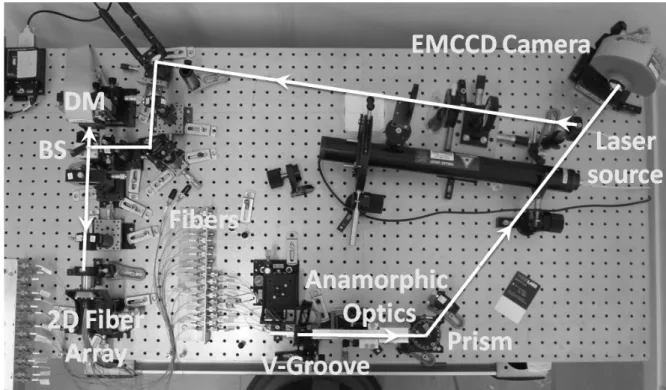
The concept of a pupil remapping interferometric imaging technique with single-mode fibers was proposed by Perrin et al8,9. FIRST utilizes a single-mode fiber array to divide an input pupil of a single telescope (Figure 1). The output pupils
will be reconfigured non-redundantly thanks to the single-mode fibers, and recombined in the image plane to measure complex fringe visibilities. Images can be reconstructed by aperture synthesis techniques. The absence of atmospheric turbulence and redundant noises allows the calibration of degraded wavefronts almost perfectly. Simulations showed that a raw dynamic range up to 106 can be realized in only a few tens of seconds of integration time for bright objects9.
Deformable Mirror 2D Fiber Array Single-mode fibers Prism Lens Interferogram Microlens array Silicon V-groove chip
3. DESCRIPTION OF THE EXPERIMENT
In this section, we describe the laboratory experiments. The experimental setup is shown in Figure 1. To demonstrate an imaging capability of this instrument, an artificial binary star was used for this experiment. An intense broad-band source is injected into 5 μm pinholes to make spatially coherent point source and collimated to be launched in the system.
Injection optics: A 37-element, segmented deformable mirror (IRIS AO) is placed in the collimated beam to align tip-tilt of each sub-aperture for precise fiber coupling. After reflection by the DM, the beam diameter is reduced by a factor of 2.4 to match the pitch of adjacent sub-apertures (606.2 μm) to the single-mode fiber array (250μm pitch) which consists of a bundle of 36 fibers (Fiberguide industries). A microlens array divides the input pupil to 36 sub-apertures and each beam is focused onto a fiber head. The fiber is a polarization maintaining fiber (PM-640HP, Nufern) optimized for operation in the R-band (the cutoff wavelength is 550 nm, NA= 0.12). Although the final system should use all 36 fibers, for simplicity only 9 fibers were used for this experiment.
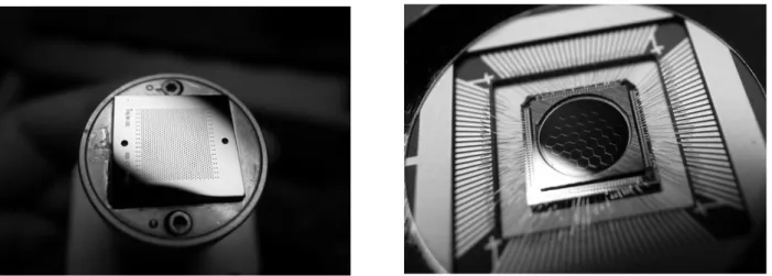
Figure 2. Left: Two-dimensional fiber array from FiberGuide Industries. The fiber pitch is 250 µm. Right: Segmented Deformable Mirror from IRIS AO. The pitch between adjacent segments is 606.2 µm including a 4 µm gap.
Beam combining optics: Output fibers are precisely aligned in a silicon v-groove chip (OZ optics) in non-redundantly and in one-dimensionally (Figure 3). The non-redundant configuration is important so that any fiber pair has unique spacing. Output beams from the fibers are recollimated by a linear microlens array. The beams are spectrally dispersed by a prism to minimize the effect of Optical Path Difference (OPD) between the fibers. The size of the Airy pattern only in the vertical direction is minimized by using an anamorphic optics to avoid losing spectral resolution, while keeping the size in the fringe direction. The design of an anamorphic system is relatively simple. It uses an afocal combination of two cylindrical lenses (f=7.5mm and f=150mm) with the ratio of their focal lengths corresponding to a magnification of a pupil diameter (~ 20), which translates into a small PSF in only one spectral dimension in the image plane. The laboratory obtained PSF image showed the anamorphic ratio of this system is about 20:1 as shown in Figure 4. For a 9-beam combiner, the optimum anamorphic ratio is 440:1, however it is difficult to achieve this due to strong spherical and chromatic aberrations of the microlens. Finally the beams are recombined on the image plane to make interference patterns. Our EMCCD camera (Andor technology Luca-S) can be read at high-frame rates (~ 37 frames/sec) for reading out a full area (658x496 pixel) and effectively very small read-out noise (<0.1 e-). These features allow this detector to be used in the photon noise limited regime.
Figure 3. Configurations of the input redundant array (up) and the output non-redundant array (bottom) used for this experiment. The white hexagons and the black filled circles show the positions of the input and output pupils respectively.
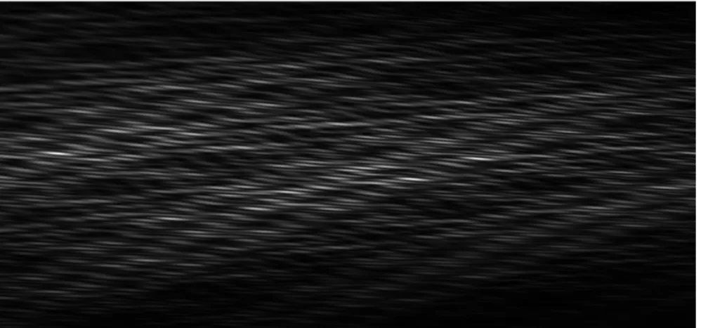
Figure 4. Interferogram with a He-Ne laser source. Because of the anamorphic optics, the horizontal size of the PSF is 20 times larger than the vertical. It allows spectral dispersion to the vertical direction.
Fiber length equalization: For broad-band observations, the effect of OPDs between fibers must be minimized in order to precisely measure fringe visibilities. For this purpose, we equalized the fiber lengths with a precision of better than 100 μm by using the technique developed at LAOG in France. In addition, spectral dispersion of the output beams reduces the effect of OPD. Figure 5 shows the spectro-interferogram obtained in our laboratory using a broad-band source (600-800nm) and the 9-fiber system. The spectral resolution was about 300. The fringe patterns are clearly seen over a wide wavelength range.
4. RESULTS
The goal of this experiment is to show that we are capable of deriving spatial structures in an object from visibility measurements. We created an artificial high-contrast binary system which has a contrast of 10-2 by using following
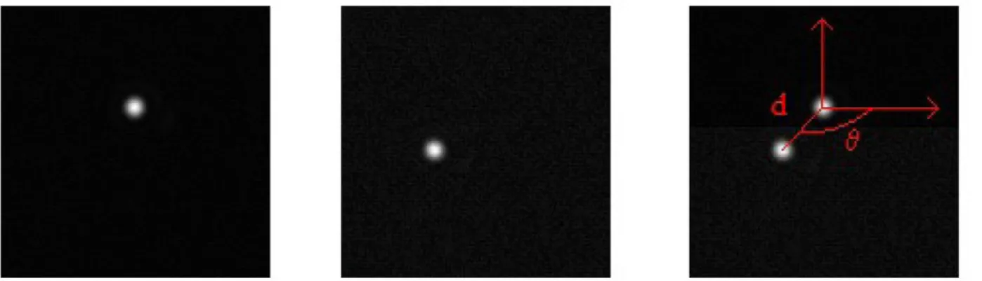
method. At first, a collimated input beam from a broad-band source (600-800nm) was amplitude divided by using a beam splitter. The two beams were returned after reflected by flat mirrors then combined by the same beamsplitter. One beam was slightly tilted and the intensity was reduced a factor of 100 compared to the other beam. In addition, about 10cm of OPD was added between two beams so as not to interfere each other. This is important to simulate a binary star system. The direct image of this artificial binary star obtained with a CCD camera is shown in Figure. 6. To derive spatial information of the objects, we fitted a binary star model to the measured visibilities at all wavelengths simultaneously. We found that the best fit binary star model well matched to the CCD image with a few percent positional errors and ~ 30% contrast error (see more detail in the caption of Figure 6).
Figure 6. Direct images of the artificial binary star with a CCD camera. Left and central images: A primary object and its companion object. The intensity of the primary is ~ 100 brighter than the companion, but the intensity level of these images is adjusted so as to see the positions of the two objects clearly. Right: Combined image of the primary and the companion. θ is a position angle, d is a sep-aration on the image plane. From the CCD image, we found θ = -136 deg, d = 135 μm, contrast = 8.5×10⁻³, whereas the best fit model
predicts θ = -133 deg, d = 138 μm, contrast = 6.0×10⁻³.
5. CONCLUSION
Our experiments have demonstrated the capability to detect a high-contrast binary system with a single-mode fiber pupil remapping system for a single telescope. We showed that there is no problem to observe a broad-band source thanks to the precise fiber length equalization. The laboratory obtained fringe visibilities for the artificial high contrast binary star (contrast ~ 10-2) well matched the theoretical model. This successful experiment is an important step toward on-sky tests.
We will test our instrument at the 3-meter Shane telescope at the Lick observatory, which is scheduled in the summer and Fall of 2010. The optical setup for the Shane telescope is shown in Figure 7.
Figure 7. Optical setup for the Lick 3-meter telescope.
ACKNOWLEDGMENTS
The authors wish to thank the Canada-France-Hawaii Telescope Corporation and CNRS/INSU for support. TK was sup-ported by a postdoctoral fellowship from Paris Observatory. STR acknowledges support by NASA grant NNH09ak731.
REFERENCES
[1] Mayor, M. and Queloz, D. “A Jupiter-Mass Companion to a Solar-Type Star”, Nature, 378, 355 (1995)
[2] Kalas, P., Graham, R., Chiang, E., Fitzgerald, M., Clampin, M., Kite, E., Stapelfeldt, K., Marois, C., Krist., J., “Optical Images of an Exosolar Planet 25 Light-Years from Earth”, Science, 322, 1345 (2008)
[3] Marois, C., Macintosh, B., Barman, T., Zuckerman, B., Song, I., Patience, J., Lafrenière, D., Doyon, R., “Direct Imaging of Multiple Planets Orbiting the Star HR 8799”, Science, 322, 1348 (2008)
[4] Guyon, O., “Limits of Adaptive Optics for High-Contrast Imaging”, ApJ, 629, 592-614 (2005)
[5] Lagrange, A.-M., Gratadour, D., Chauvin, G., Fusco, T., Ehrenreich, D., Mouillet, D., Rousset, G., Rouan, D., Allard, F., Gendron, E'., Charton, J., Mugnier, L., Rabou, P., Montri, J., Lacombe, F.A, “A probable giant planet imaged in the β Pictoris disk. VLT/NaCo deep L'-band imaging”
[6] Labeyrie, A., “Attainment of Diffraction Limited Resolution in Large Telescopes by Fourier Analysing Speckle Patterns in Star Images”, A&A, 6, 85 (1970).
[7] Weigelt, G., “Modified astronomical speckle interferometry speckle masking”, Opt. Commun., 21, 55-59 (1977).
[8] Haniff, C. A., Mackay, C. D., Titterington, D. J., Sivia, D., Baldwin, J. E., “The first images from optical aperture synthesis”, Nature, 328, 694-696 (1987).
[9] Tuthill, P. G., Monnier, J. D., Danchi, W. C., Wishnow, E. H., Haniff, C., “Michelson Interferometry with the Keck I Telescope”, PASP, 112, 555-565 (2000).
[10] Lacour, S., Meimon, S., Thiébaut, E., Perrin, G., Verhoelst, T., Pedretti, E., Schuller, P. A., Mugnier, L., Monnier, J., Berger, J. P., Haubois, X., Poncelet, A., Le Besnerais, G., Eriksson, K., Millan-Gabet, R., Ragland, S., Lacasse, M., Traub, W., “The limb-darkened Arcturus: imaging with the IOTA/IONIC interferometer,” A&A 485, 561–570 (2008) [11] Perrin, G., Lacour, S., Woillez, J., Thiébaut, E., “High dynamic range imaging by pupil
single-mode filtering and remapping”, MNRAS, 373, 747-751 (2006).
[12] Lacour, S., Thiébaut, E., Perrin, G., “High dynamic range imaging with a single-mode pupil remapping system: a self-calibration algorithm for redundant interferometric arrays”, MNRAS, 374, 832-846 (2007).
[13] Kotani, T., Lacour, S., Perrin, G., Robertson, G., Tuthill, P., “Pupil remapping for high contrast astronomy: results from an optical testbed”, Optics Express, 17, 1925-1934 (2009)