HAL Id: hal-01006857
https://hal.archives-ouvertes.fr/hal-01006857
Submitted on 7 Jul 2018
HAL is a multi-disciplinary open access
archive for the deposit and dissemination of
sci-entific research documents, whether they are
pub-lished or not. The documents may come from
teaching and research institutions in France or
abroad, or from public or private research centers.
L’archive ouverte pluridisciplinaire HAL, est
destinée au dépôt et à la diffusion de documents
scientifiques de niveau recherche, publiés ou non,
émanant des établissements d’enseignement et de
recherche français ou étrangers, des laboratoires
publics ou privés.
Exploring material flow in friction stir welding : tool
eccentricity and formation of banded structures
François Gratecap, Marion Girard, Surendar Marya, Guillaume Racineux
To cite this version:
François Gratecap, Marion Girard, Surendar Marya, Guillaume Racineux. Exploring material flow
in friction stir welding : tool eccentricity and formation of banded structures. International Journal
of Material Forming, Springer Verlag, 2012, 5 (2), pp.99-107. �10.1007/s12289-010-1008-5�.
�hal-01006857�
Exploring material flow in friction stir welding: Tool
eccentricity and formation of banded structures
F. Gratecap&M. Girard&S. Marya&G. Racineux
Abstract Surface striations with spacing equal to feed rate per rotation and banded structures in the weld nugget are some of the striking features of friction stir welding. However, their formation is still subject to some debate. This study contributes to comprehend their formation by evaluating the possible role played by the eccentricity of the tool during the welding of an aluminium alloy and using a plasticine as its analogue. The eccentric movement is visualized to generate both surface and bulk striations in plasticine. By voluntarily using non optimized welding conditions on aluminium, the material flow has been deduced and confronted with direct visual observations through high speed camera on plasticine. In the non closed section of the weld, two lobes each with thickness equal to feed rate per rotation were observed. First lobe corresponds to flow induced by the pin and tests on plasticine showed constant volume displacement per rotation for a given tool eccentricity. The second lobe is generated by material flow from under the shoulder back to the rear of the pin. The assembling or not of these two lobs behind the pin can explain some of the characteristic patterns observed in the weld nugget such as onion rings, oxide dispersions and cavities.
Keywords Friction stir welding . Eccentricity . Mixing . Material flow . Band spacing
Introduction
Friction stir welding ever since its invention has undergone extensive academic investigations and demonstrated its viability in industrial applications. Investigations on friction stir welding have so far mainly focused on developing tools and procedures for making welds in a variety of alloys, characterizing the properties of welds for allowable designs and investigating the possible flow mechanisms in and around the weld nugget. The tool design is of prime importance in explicating temperature fields and material movement patterns in FSW. The process involves a milling type machine with different degrees of freedom. The tool generally consists of a shank, a shoulder and a pin that is adjusted to a certain height inside the work pieces to be welded. The tool is rotated and a relative displacement motion along the weld line is generated. Different tool geometries from a simple pin to complex threads have been proposed and investigated. The basic idea behind the process is the generation of heat by friction between the tool and workpieces and its plasticization with rubbing from the moving tool. The induced material deformation originates by dry rubbing, lubricated and sticking depending on the processing conditions and material chemistry. Under optimized conditions, the hole left behind by the advancing tool is filled by material input generated by the forward motion of the tool. As the tool rotates and advances in a very continuous manner, the process is supposed to leave a weld surface without any print marks other than those arising from the tool’s surface itself. However, one of the striking features of FSW nuggets is the presence of striations with spacing equal to forward motion (Vf, mm/minute) per rotation
(N, rotations/minute) [1, 2]. Other types of striations and patterns in the weld nugget have been observed and characterized. For example, the formation of typical onion
F. Gratecap
:
M. Girard:
S. Marya:
G. Racineux (*)Institut de recherche en génie civil et mécanique (GeM) - UMR CNRS 6183,
Ecole Centrale de Nantes - 1 rue de la Noë, 44321, Nantes cedex 3, France
rings in the transverse cross-section of the nugget, the formation of striations in the longitudinal sections and to a lesser extent, the distribution of typical oxide patterns in different sections of the weld [3,4]. The contribution of the material flow patterns around the moving tool on the formation of different banded structures of the weld nugget has been proposed. Investigations of flow patterns involve deductive conclusions from post mortem specimens by materializing tracer distribution in the weld or by tool piece frozen experiments [5]. Though tracer techniques suffer from possible discontinuities generated in material flow by their presence, they still offer the best possible channel to study material flow. For example, Colligan et al. [6] used the steel shot tracer technique in conjunction with a screw threaded pin and concluded limited stirring of the surface material and extrusion of the other materials on the retreating side of the nugget. Lorrain et al. [7] made welds using two different tool profiles and copper foils as material marker. Zettler et al. [2] used Ti powder markers for different aluminium alloys and investigated material flow by using different tool geometries. They showed a good correlation between the feed rate per rotation and band spacing whatever the tool geometry, though significant temperature field differences could be found between different tool geometries. In fact, the published literature suggests that striations arise from separation of the material flow pulled in to the stir zone from either side of the joint. From tracer techniques, the flow patterns are visualized as shearing from the advancing side followed by the material flow from the retreating side in far field of the pin. Thus, in the nearest flow field, closest to the pin, the material originates from the advancing side and is forced to flow to the other side of the joint. Material from the retreating side enters the stir zone as a separate entity from behind the tool pin due to the lower pressure generated there by the advancing tool. The two flows do not mix in real sense of term and generate layered structures. In case of dissimilar joints Larsson et al. [8], while intimating bonding is observed, the analysis of composition profiles generally shows only a very limited mixing, which supports the flow observations from tracer studies. Further onion rings, striking features of FSW seem to result from extrusion of the cylindrical sheets of the material during each rotation of the tool and according to Krishnan [9] explains one to one relation between the spacing of the marking and forward motion of the tool per rotation. The basic ideas derived from observed or deduced flow patterns support stirring and extrusion as dominating mechanisms. Regarding the oxide patterns reported by Jene et al. [10], a good correlation between the oscillating oxides and the measured forces in transverse and longitudinal sections of wrought Al alloy AA5454 has been reported. The periodic length of the measured forces and the oxide patterns correlated closely with the feed rate per rotation (FPR). However the cause and
effect relation is not clearly established. It is not sure if in the absence of the oxide patterns, the oscillating forces would vanish or not. The force plot suggested a circular motion of the tool, caused by the unbalanced mass of the tool or the asymmetric friction stir itself due to difference on the advancing and retreating sides. The effect of eccentric weld tool, whatever the reason, on the formation of different pattern characteristics remains comparatively scarce. This work proposes to contribute to this problematic by reporting a number of observations made on FSW welds on aluminium substantiated by investigations on plasticine as analogue material. It is worth mentioning that plasticine has previously been used to model forging and extrusion characteristics and offers a simple way to understand possible flow characteristics of metals. More recently Leichty et al. [11] used plasticine to explore flow character-istics in friction stir welding as it shows typical stress strain behaviour with temperature and strain rates as metals. Further due to very low stresses encountered by the tool in plasticine, any observed eccentricity would arise mainly from tooling itself. In case of metals, reaction forces between metal and tool may account for some generated eccentricity. Recently, Kumar et al. [12] proposed a special experiment, where the interaction of the friction stir welding tool with the base material is continuously increased. The results show that there are two different modes of material flow regimes involved in the friction stir weld formation; namely “pin-driven flow” and “shoulder-driven flow”. The objective of this study is thus to report the effect of tool eccentricity on observed flow patterns in an aluminium alloy and get better insight of their formation by matching with those on plasticine in carefully designed set of experiments. The reported results point out a very strong similarity of observed patterns and direct observation of flow in plasticine gives interesting qualitative clues to possible material flow in aluminium during the friction stir welding process.
Experimental method
The work is mainly focused on 4 mm thick aluminium alloy 2017-T4 plates and plasticine of similar thickness obtained by rolling. In this study four tools were used. The first one is a conventional FSW tool made from quenched & tempered steel with a 10 mm radius shoulder and 3 mm radius conical smooth pin (Fig. 1a). The second one is a cylindrical tool without any shoulder (Fig. 1b). The third and fourth was cylindrical with 3 and 4 milled faces at the bottom (Fig.1cand d). Preliminary studies showed strong similarities in the profiles (surface markings, end hole.) of stirred zones between FSW of aluminium and plasticine for a given tool geometry but with understandably different working conditions. The FSW experiments were carried out
on a GSP numerical milling machine. The FSW experi-ments are displacement controlled. Aluminium plates are rigidly fixed between clamped bars and care is taken to ensure that no lateral movement during work occurs. In order to minimize heat loss through the machine table, the workpieces were clamped on a backing plate in titanium. The heat loss effect is insignificant for plasticine, but becomes measurable for aluminium with high thermal conductivity. Gratecap [12] reported that the presence of titanium supporting plate improved the consistency of test results on aluminium plates and this set up was maintained as a conservative measure in subsequent investigations. However, as the objective of this study is to understand material flow during FSW process by using plasticine, the presence of backing Ti plate would not affect the results. Temperature rise if any is quite negligible during tool advance in plasticine in contrast to aluminium. The FSW tool is fixed in the vertical broche of the milling machine with screws threaded across the thickness of the broche. The striations and flow patterns are observed by using
optical microscopy and scanning electron microscope for aluminium. A direct observation of flow patterns in plasticine is looked by high speed camera with capture rate of 125 pictures/s. In general, the advance rate Vf ranged
from 70 to 200 mm/min and rotational speeds N was varied from 400 to 850 rpm.
Results and discussion
Typical striations of Fig. 2a on aluminium with spacing equal to feed per rotation (Vf/N =0.44 mm/round) are
observed and this is the general case with all experiments with feed rates and rotational speeds varying respectively from 50 to 300 mm/min and from 200 to 1000 rpm. Even if the weld parameters are slightly varied from the optimized values, these striations always prevail, but the weld may show some continuous unfilled open tunnel in the terminal part of the weld. The bottom as well as the tunnel side walls (Fig.2bandc) shows striations with spacing of the feed per
Fig. 1 a Conical tool withβ=21.7°, γ=8°, h=3.9mm, Ds=20mm, Dp=6mm b Cylindrical tool c tool with three milled faces d tool with four
milled faces pin
a
b
Tunnel side wall
Tunnel
Upper weld surface
20 mm – 45 striations (Vf/N = 20/45 = 0.44)
c
Fig. 2 N=450 rpm, Vf=200 mm/min, Vf/N=0.44 a Surface striations on Al 2017 with spacing equal to Vf/N, Vfis advancing speed (mm/minute) and N (rpm) the tool rotational speed, b side striations on longitudinal section of the tunnel on aluminium, c striations on the bottom of the tunnel
rotation. For the introduction of the mentioned tunnel defect in the stir zone, the tool was slightly lifted above the workpiece from its optimized value that was determined from tool-processing condition window [13,14]. By slightly lifting the tool above the workpiece, the forging conditions become insufficient to completely fill the rear of the weld and an open tunnel close to the advancing side was formed.
Further, the left terminal hole, once the tool is removed, depicts two weld lobes (Fig.3a) with typical striations. The lobes seem to form by the addition or superposition of layers of thickness representing the feed per rotation (Fig.3c andd). The observation of the lobes is first of its kind and certainly gives clue to what happens during the friction stir welding. As shown later on, the lower and the upper lobe are respectively generated by flow around the pin and the upper shoulder which transfers the material from front to the rear of the advancing tool. Figure 3b
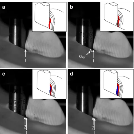
shows a very similar profile in the hole left by tool removal in the plasticine. Here, the conditions are different from those used for aluminium. For a better inside on these striations and lobes, simulated weld runs were made on a bloc of plasticine. In one series of the experiments, only pin was used, while in other series the whole FSW tool containing both pin and shoulder were used so as to differentiate the role of pin and shoulder. Figure 4 shows four stills taken from high speed camera. In plasticine, without shoulder, the rotation and translation of the tool yields an opening of width of size of the pin diameter and on the retreating side, a succession of layers similar to striations can be seen. The observations of the tool rotation
and stacking of layers by using high speed camera revealed that the pin did not execute a completely concentric rotation, but showed an eccentricity of 0,03 mm. This is small, but its effect could be perceived as shown in Fig. 4
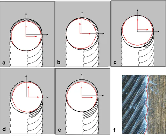
where after the formation of a layer, follows a period in which tool looses contact with the formed layer i.e., a gap is generated and then again a new layer is built up on the previous one. A succession of layer additions in a discontinuous manner generates the typical striation pattern on the side walls with spacing of the feed rate per rotation. The temporary creation of gap is related to the eccentricity, a period during which the pin suddenly moves to the forward side of tool translation. During each rotation, the eccentricity of the rotating tool pin generates additional oscillatory movement in the stir zone as illustrated by the evolving position of the blue circle in Fig.5with reference to the red circle. The process is thus discontinuous in spite of the continuous constant advance of the tool carrying system. Here again, the number of stacked layers is governed by feed rate per rotation as shown schematically by Fig.5. Each stacked layer can be further divided if the circular pin sections are replaced by milled facets. For example, Fig. 6 depicts three layers for three milled faces and four layers with four milled faces pin. As the number of stacked layers for a given feed rate per rotation increases with the number of milled facets, the separation between layers decreases and for a circular pin, it is expected that the number of layers would tend towards infinite which would make individual layers difficult to differentiate. This is what happens with non faceted pin where only visible layers are
Fig. 3 a Observation of two lobes (upper and lower marked by circled arrows) in the terminal hole left by tool (b) similar lobes on plasticine (c) striations on the lower (d) and upper lobe
those generated by feed rate per rotation. Three or four striations observed in Fig.6 occupy the same space as the layer of the circular pin without milled faces. When pin with shoulder is used to simulate the weld, then the opening left by pin motion is closed and observation of the flow patterns is impossible. The formation of lobes both in aluminium and in plasticine reported earlier (Fig. 3) supports the idea that the latter could help further in understanding material flow generated by the rotating tool. For example, it is difficult to study in-situ material flow in aluminium other than by tracer technique and post mortem metallographic analysis. On the contrary, plasticine offers alternative route to visualize material flow in FSW, though the working conditions would be completely different. For example, temperature gradients prevail in metals during FSW, but these are quasi inexistent in plasticine. The macroscopic process mechanisms were thus investigated on plasticine by designing the experimental procedure such that camera could see the motion of the tool and the material flow.
In order to visualize macroscopic phenomenon occurring in FSW, the tool pin was inserted about three quarters into the plasticine so as to leave an open space for observation. Figure7ashows an extracted image from the film and one can notice the material coming down from the front to the back via the shoulder. Further, material layered by the pin
comes from the retreating side and junction between these two lobes generates the weld. These lobes and stacking layer profiles are also seen on the side wall of the tunnel on aluminium (Fig. 7bandc). There is a very close similarity between the lobe formation seen through video on plasticine and frozen observation of the tunnel wall in aluminium. The lower lobe created by the pin is difficult to discern from the images of the Fig.7a, but its presence is much more precisely seen from the layered structures on the retreating side when the shoulder of the tool is removed i.e., tool is a simple pin. With this arrangement, the tool leaves a open tunnel with visible side walls that contain typical stacked structures observed here.
Figure8 shows layered structures on the retreating side as related with advance per rotation. With its reduction, the layers become more and more difficult to distinguish as can be seen when Vf/N passes from 2 to 0, 125 mm/min. Besides the layers, the Fig. 8 shows plasticine extruded well above the base on the retreating side. The presence of the shoulder blocks this material extrusion generated by the pin itself which then fills in the trench observed without shoulder. The stacks of layers are formed at each rotation of the tool which in our study revealed tinuous feed following its eccentric rotation. The discon-tinuous nature of material flow results in three dimensional discontinuities which lead to different
stack-1 1 Gap 1
2
12
a
b
c
d
Fig. 4 High speed video sequence (125 pictures/s) illustrating the formation of successive stacked layers on the simulated retreating side on plasticine. Tool 2 without shoulder (Fig.1b)
ing structures revealed here on aluminium and on plasticine. From metallographic studies, Krishnan [9] have attributed the onion rings observed in the cross-section of the weld nugget to such stacking layers. The formation of the surface striations is markedly explicated by the schematic diagram of Fig.9.
Due to the tilt and eccentric motion of the tool, the surface effect is as well transferred to the material in its volume which explains different banded or layered struc-tures. Whatever the tool’s eccentricity, the spacing will remain constant for a given feed per rotation. However, the quantity of material involved for a given feed per rotation
will increase with increasing eccentricity. As spacing between striations depends mainly on advance per rotation, more material involvement with increasing eccentricity would generate thicker layers. The Fig. 9a also supports the up and down movement related to the tool eccentricity as striations on the bottom of the tunnel can (Fig.7) only be generated by variable contact in between plasticine and the pin.
The stacking of layers and the formation of lobes with stacked layer structures can contribute to explicit some published results. For example, Fig. 10 shows the XX (plane A) and YY (plane B) sections. As the welding
a
b
Fig. 6 Effect of milled faces on conical pin with the same Vf/N=1 mm/round. Each stacked layer is segmented into 3 (a) or four 4 (b) occupying the same space equal to Vf/N
a
b
c
d
e
f
Fig. 5 Schematics (a to e) of layer stacking representing successive sequences with eccentric tool. In (e), the rotation is complete with an additional layer compared to (a). f Optical view of zigzag interface resulting from eccentric motion of the tool in line with schematics of fig a to e
progresses by the welding of the stacked layers on the two lobes, their sectional views depict typical oxide structures observed by Jene et al. [10]. It is anticipated that the oxides would principally be formed on the exposed stacked layers which following interaction of the two lobes and their subsequent welding would leave the typical oxide patterns. Further as material flow occurs by a succession of material flow in synchrony with the tool oscillation due to its eccentricity, the different forces acting on the tool would equally show periodic variations with the period of striations. This is what has been explicitly reported by Jene et al. Though significant data correlation is still needed, the hole formation or tunnelling in the weld bead would result from insufficient pressure to completely bring the material flowing under the shoulder (upper lobe) sufficiently bring it in contact with the lower lobe generated by the pin rotation and translation.
Conclusions
The present study on an aluminium alloy supplemented with tests on plasticine show some interesting features that substantiate results of other researchers. One of the important features detected by high speed camera has been that the tool as a whole has an eccentric rotation movement. This generates oscillatory movement and leads to a discontinuous welding process from material perspectives in an otherwise continuous rotation translation picture of the tool. The origin of the eccentricity in the present case stem from the FSW tool attachment in the tool holder of the milling machine. In other cases, the eccentricity may also be caused by the different transverse forces from the advancing and retreating sides of the weld. This machine tool fixation aspect has very been often been neglected in explicating different flow theories around the pin and shoulder.
Vf/N = 2 mm/tr
Vf/N = 0,5 mm/tr Vf/N = 0,125 mm/tr
Fig. 8 Striations on the retreating side of plasticine with tool 2. Spacing equals Vf/N. Pin extruded plasticine can be seen beyond the thickness of the experimental plate
A A
a
b
c
Upper lobe Lower lobe Upper lobe Lower lobe Base striationsFig. 7 a Video image on plasticine with tool 1, upper lobe is clearly identified as originating from the shoulder, the lower lobe from the side can be vaguely seen. For this observation, tool penetration from
the longitudinal side is 0.75× pin diameter (b) tunnel observed on aluminium and observation of lobes with stacked layers (c)
The eccentricity reported here is very small, less than 0, 03 mm. The principal results may be summarized as follows:
1. Surface striations and stacked layer structures on different sections of the weld seem to correlate with the oscillatory motion of the rotating and advancing tool.
2. The above mentioned oscillatory motion is caused by its eccentric positioning with reference to the spindle as shown by high speed video captures of tool’s advance in plasticine.
3. The eccentricity of the tool may result from the architecture of tool fixation in the broche of FSW machine alone or combined with the effect of the restraining forces when the workpiece material is resistant.
4. Spacing between stacked layers and striations is equal to advance per rotation
5. Stacking of the layers is discontinuous and correlated with eccentric forward-backward motion of the tool 6. High speed camera observations on plasticine showed
two main tracks of material flow. One under the tool shoulder and the second one generated by the pin 7. These two types of material flow generates two lobes,
each one with stacked structures
8. Welding is successfully accomplished when the pro-cessing conditions are such that the two lobes com-pletely merge behind the advancing tool.
9. The two lobes, each with stacked layers, can explain the formation of reported wavy oxide patterns on aluminium.
Vf / N
hs
a
b
Fig. 9 Schematics of surface striations following up and down motion of the tilted tool on plasticine. Striation thickness increases with tool eccentricity and tilt at constant Vf/N
Fig. 10 a Schematic illustration of weld lobes and definition of longitudinal (AA) and cross sectional (BB) plane (b) and c formation of periodic oxide patterns by layer stacking in longitudinal (AA) and cross-sectional sections (BB) [10]
Though further studies are still required, this work underlines the importance of the machine tool alignments and fixtures in the welding process. This aspect has often been neglected in the past.
References
1. Chen ZW, Pasang T, Qi Y (2007) Shear flow and formation of nugget zone during friction stir welding of aluminium alloy 5083-o. Materials Science and Engineering A
2. Zettler R, dos Santos JF, Donath T, Beckmann F, Lohwasser D (2006) Material flow in friction stir butt welded aluminium alloys. 6th Symposium on friction stir welding, St Sauveur, QC, Canada 3. Zettler R, Blanco AC, dos Santos JF, Marya S (2005) The effect of process parameters and tool geometry in friction stir welding of the alloys az31 and az61. Magnesium Technology, TMS 4. Chen HB, Yan K, Lin T, Chena SC, Jiang CY, Zhaob Y (2006)
The investigation of typical welding defects for 5456 aluminum alloy friction stir welds. Mater Sci Eng, A 433:64–69
5. Dickerson T, Shercliff HR, Schmidt H (2003) A weld marker technique for flow visualization in friction stir welding. 4th International Symposium on Friction Stir Welding, Utah, USA
6. Colligan K (1999) Material flow behaviour durinf friction stir welding of aluminium. Weld Res Suppl 78:7
7. Lorrain O, Favier V, Zahrouni H, Lawrjaniec D (2010) Under-standing the material flow path of friction stir welding process using unthreaded tools. J Mater Process Technol 210:603–609 8. Larsson H et al (2000) Joining of dissimilar al-alloys by friction
stir welding. 2nd International Conference on Friction Stir Welds, Gothenburg, Sweden
9. Krishnan KN (2001) On the formation of onion rings in friction stir welding. Mater Sci Eng, A 327:246–251
10. Jene T, Dobmann G, Wagner G (2006) Oxide fragments in friction stir welds-distribution and effects on crack initiation. 6th Symposium on friction stir welding, St Sauveur, QC, Canada 11. Liechty BC, Webb BW (2006) The use of plasticine as an analog
to explore material flow in friction stir welding. Journal of Materials Processing Technology
12. Kumar K, Kailas Satish V (2008) The role of friction stir welding tool on materialflow and weld formation. Mater Sci Eng, A 485:367–374
13. Gratecap F (2007) Contribution to friction stir welding process, Doctoral Thesis, Ecole Centrale de Nantes, France, 14 december
14. Gratecap F, Racineux G, Marya S (2008) A simple methodology to define conical tool geometry and welding parameters in friction stir welding. Int J Mater Form 1:143–158