Characterization and Modelling of Packed-stuffing Boxes
by
Mehdi KAZEMINIA
MANUSCRIPT-BASED THESIS PRESENTED TO ÉCOLE DE
TECHNOLOGIE SUPÉRIEURE IN PARTIAL FULFILLMENT FOR THE
DEGREE OF DOCTOR OF PHILOSOPHY
Ph.D.
MONTREAL, FEBRUARY 17, 2017
ÉCOLE DE TECHNOLOGIE SUPÉRIEURE
UNIVERSITÉ DU QUÉBEC
This Creative Commons license allows readers to download this work and share it with others as long as the author is credited. The content of this work may not be modified in anyway or used commercially.
BOARD OF EXAMINERS
THIS THESIS HAS BEEN EVALUATED BY THE FOLLOWING BOARD OF EXAMINERS
Mr. Abdel-Hakim Bouzid, Thesis Supervisor
Département de génie mécanique at École de technologie supérieure
Mr. Vladimir Brailovski, Member, Board of Examiners
Département de génie mécanique at École de technologie supérieure
Mr. Tan Pham, Member, Board of Examiners
Département de génie mécanique at École de technologie supérieure
Mr. Lotfi Guizani, Chair of the jury
Département de génie de la Construction at École de technologie supérieure
Mr. Ali Benmeddour, External Evaluator Research Officer, CNRC, Ottawa Canada
THIS THESIS WAS PRENSENTED AND DEFENDED
IN THE PRESENCE OF A BOARD OF EXAMINERS AND THE PUBLIC 12 DECEMBER, 2016
ACKNOWLEDGMENTS
At first and foremost, I would like to express my sincere gratitude to my research director, Professor Abdel-Hakim Bouzid for providing the honorable chance to pursue my Ph.D. studies in the Static and Dynamic Sealing Laboratory, and sharing his experiences and expertise within my doctorate program. Hereby I appreciate all his valuable supports, mentorships and guidance.
I would like to express my appreciation to my wife, Maryam, for her help and patience. Thanks for always being supportive and encouraging me to finish my graduate studies.
Thanks to my parents Parvaneh and Mehrali for their support and understanding despite of being thousands miles away far from them.
I also would like to present my special thanks to the technicians of the department of Mechanical Engineering of ÉTS and in particular Messrs Serge Plamondon and Alain Grimard and to the application engineers Messrs. Michel Drouin and Eric Marcoux for their collaboration and technical support for the experimental study.
I wish to thanks all my colleagues and friends in the Static and Dynamic Laboratory for their friendship and support. Heartfelt thanks for all of those good times and company.
CARACTERISATION ET MODELISATION DES PRESSE-ÉTOUPES Mehdi KAZEMINIA
RÉSUMÉ
Le souci global des changements climatiques et environnementaux et de la réduction des gaz à effet de serre a mené à l’implémentation des réglementations strictes concernant les émissions fugitives. Le secteur industriel contribue massivement à la production des émissions fugitives. Selon l’Agence américaine de protection de l’environnement (EPA), 60 % de ces émissions proviennent des valves. Ainsi, certaines organisations comme l’ISO et l’API ont commencé au début des années ‘90 le développement d’un code de standards pour qualifier l’étanchéité des valves. Cependant, il manque toujours une procédure de conception standardisée pour les valves avec presse-étoupe et pour la sélection de matériels appropriés à l’amélioration de l’étanchéité. L’objectif principal de cette thèse est d’introduire une procédure permettant la caractérisation d’étanchéité et de développer une procédure de conception standard pour les valves avec presse-étoupe.
Pour réaliser ces objectifs, une série de modèles théoriques, appuyée par des études expérimentales, ont été élaborées pour caractériser l’étanchéité et les interactions entre les différents composants d’un presse-étoupe. Ces études expérimentales ont été effectuées sur un banc d’essai équipé avec des instruments de mesures standards et de haute précision pour faire des simulations pratiques d’applications réelles et pour rapporter les données concernant l’étanchéité des divers systèmes qui ont été utilisés. Des bagues de garnitures en graphite souple (qui ont servi de scellant), différents niveaux de compression et trois fluides (hélium, azote et argon) ont été appliqués dans le plan de contrôle. Le modèle théorique utilisé pour l’intégrité mécanique est une combinaison de deux théories ; le théorème cylindres épais de Lamé et la théorie de poutres sur fondations à gradient. En outre, trois approches différentes (la loi de Darcy modifiée, les cylindres concentriques et la pression capillaire) ont été utilisées pour caractériser l’étanchéité des bagues de garniture.
Les résultats, considérant l’accord significatif entre les théories et les mesures d’essaies, ont établi la fiabilité des procédures proposées pour la caractérisation de l’intégrité mécanique et de l’étanchéité des valves avec presse-étoupes. Également, les résultats témoignent aussi qu’un angle ouvert et conique au mur intérieur du boîtier permet d’améliorer l’étanchéité d’un presse-étoupe.
Mots Clés : Valve avec presse-étoupe, étanchéité, micro et nano fluides dans les milieux poreux, modèle constitutif
CHARACTERIZATION AND MODELING OF PACKED-STUFFING BOXES Mehdi KAZEMINIA
ABSTRACT
The global concern of the climate and environmental changes and the increase of greenhouse gases has led to the adoption of strict regulations on fugitive emissions. The industrial sector contributes significantly to the production of fugitive emissions. Aaccording to the Environmental Protection Agency (EPA), 60% of emissions from equipment devices are attributed to valves. As a result, standard organizations such as ISO and API developed new standard test procedures to qualify the sealing performance of valves. However, there remains lack of standard design procedure for stuffing-box valves and selection of proper materials to improve their sealing performance. The main objective of this thesis is to introduce a procedure to characterize sealing performance and develop a standard design procedure for stuffing-box valves.
In order to fulfill these objectives, theoretical models supported by a series of experimental tests were constructed to characterize the sealing performance and evaluate the integrity of stuffing-boxes. The experimental investigations were carried out on a test bench equipped with high accuracy instrumentation to practically simulate real applications and to record the sealing behavior of the systems. Packing rings made of flexible graphite (which were used as a sealant), various levels of compression stress, and three different fluids (helium, argon and nitrogen) were applied in the test plan. The theoretical model for mechanical integrity was a combination of theories; thick cylinders (Lame) and the theory for beams on elastic foundations. Furthermore, three different approaches (Modified Darcy, concentric cylinders and capillary models) were used to characterize the porosity and its influence on the sealing performance of packing rings.
The results, when considering the significant agreement between the theory and test measurements, proved the reliability of the proposed procedures for the characterization of mechanical integrity and sealing performance of stuffing-boxes valves. The results also demonstrated that an open and tapered angle on the internal wall of the housing is useful in improving the sealing performance of a stuffing-box.
Keywords: Stuffing-box Valve, Sealing Performance, Micro and Nano fluids in porous media, Constitutive model
TABLE OF CONTENTS
Page
INTRODUCTION ...1
CHAPITRE 1 LITERATURE REVIEW ...9
1.1 Introduction ...9
1.2 Standards and documented codes ...9
1.3 Analytical studies ...14
1.4 Numerical simulations ...25
1.5 Experimental investigations ...31
1.6 Conclusion ...43
1.7 Research project objectives ...45
CHAPITRE 2 EXPERIMENTAL SET-UP ...47
2.1 Introduction ...47
2.2 Packed stuffing box test rig ...48
2.2.1 Packed stuffing box assembly at room Temperature ... 50
2.2.2 Packed stuffing box assembly at high temperature ... 52
2.2.3 Pressurization system ... 56
2.2.4 Hydraulic system ... 56
2.2.5 Leak detection methods ... 59
2.3 Instrumentation and control ...63
1.1 Data acquisition and control system ...64
2.4 Test procedure ...65
CHAPITRE 3 STRESSES ANALYSIS OF PACKED STUFFING-BOXES ...69
3.1 Abstract ...69
3.2 Introduction ...71
3.3 Analytical analysis ...73
3.3.1 Packing ring contact analysis ... 74
3.3.2 Analysis of the housing ... 75
3.3.3 Ring analysis ... 79
3.3.4 Compatibility of displacement and rotation at the junctions ... 80
3.4 Numerical simulation ...81
3.5 Experimental investigation ...83
3.6 Results and discussion ...85
3.7 Conclusion ...90
CHAPITRE 4 EVALUATION OF LEAKAGE THROUGH GRAPHITE-BASED COMPRESSION PACKING RINGS ...91
4.1 Abstract ...91
4.2 Introduction and background ...93
4.3 Physical model ...97
4.4 Experimental setup...99
4.5 Correlation and results ...101
4.5.1 Intrinsic Permeability ... 102
4.5.2 Diffusivity parameter ... 104
4.6 Leak predictions ...105
4.7 Conclusion ...108
CHAPITRE 5 LEAK PREDICTION METHODS THROUGH POROUS COMPRESSED PACKING RINGS: A COMPARISON STUDY ...109
5.1 Abstract ...109
5.2 Introduction ...110
5.3 Physical model ...113
5.3.1 Capillary model ... 115
5.3.2 Concentric cylinders model ... 116
5.3.3 Modified Darcy model ... 117
5.4 Experimental set up...118
5.5 Exploitation of constitutive parameters ...121
5.5.1 Porosity parameters of the capillary model ... 121
5.5.2 Porosity parameters of the concentric cylinder model ... 122
5.5.3 Parameters of the modified Darcy's model ... 123
5.6 Leak rate prediction ...126
5.7 Conclusion ...129
CHAPITRE 6 EFFECT OF TAPERED HOUSING ON THE AXIAL STRESS DISTRIBUTION IN A STUFFING-BOX PACKING ...131
6.1 Abstract ...131
6.2 Introduction ...132
6.3 Theoretical background ...133
6.4 Analytical modeling ...134
6.5 FEM simulation ...140
6.6 Results and discussion ...141
CHAPITRE 7 CHARACTERIZATION AND MODELLING OF TIME-DEPENDENT BEHAVIOUR OF BRAIDED PACKING RINGS ...147
7.1 Abstract ...147
7.2 Introduction ...149
7.3 Backgraound ...150
7.4 Physical Model...151
7.5 Experimental Set-up...156
7.6 Results and discussion ...158
7.7 Conclusion ...161
APPENDIX A ….. ...171 BIBLIOGRAPHY. ...175
LIST OF TABLES
Page Table 1.1 Average gaseous emissions (leakage) and valve gaskets
(Heymanns Verlag, C. (2002)) ... 14
Table 1.2 Determined values from the test apparatus presented in Figure 1.18 ... 34
Table 1.3 The results of the test apparatus designed by Pengyun (Pengyun, 1991) ... 37
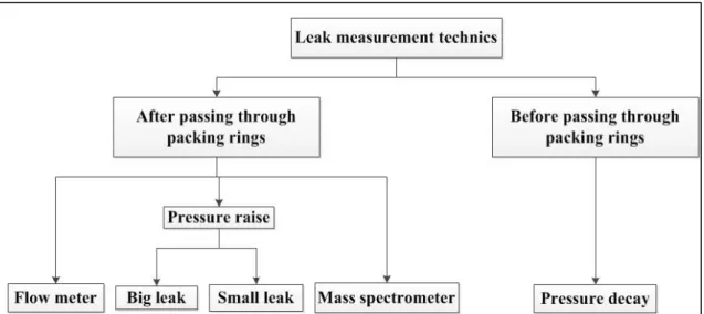
Table 2.1 Leak measurement techniques and pneumatic valve set-up ... 63
Table 2.2 Test procedures for leak detection and creep/relaxation tests ... 68
Table 3.1 Sign coefficients and moment arm ... 80
Table 3.2 The mechanical and dimensional values used in the numerical and analytical investigations ... 82
Table 5.1 Physical properties of the gases used in experimental investigations ... 120
Table 5.2 Porosity parameters for the two models ... 122
Table 5.3 Parameters of modified Darcy’s model ... 126
Table 6.1 Mechanical and geometrical properties used in the numerical and analytical simulations ... 141
LIST OF FIGURES
Page
Figure 0.1 Some basic parts in a valve (CRANE CPE) ……….. ... .1 Figure 0.2 Typical distribution of fugitive emission sources in a refineries by
EPA………...3 Figure 1.1 Test device for (a) API-622, (b) API-624 and (c) ISO (FSA, Sealing
Sense (2012)) ... 11 Figure 1.2 A schematic sample of industrial valve with stuffing-box packing (
ISO 15848 / TA-Luft, 2012) ... 15 Figure 1.3 Sectional view of packed stuffing-box (Diany and Bouzid, 2006) ... 15 Figure 1.4 Forces acting on a packing element, (a) General model and (b)
Simplified model (Pengyun et al., 1998) ... 16 Figure 1.5 Stresses on a packing (Diany and Bouzid, (2006)) ... 19 Figure 1.6 Free body diagram of elements in a stuffing-box packing (Diany and
Bouzid, 2009(a)) ... 20 Figure 1.7 A generalized Maxwell model (Diany and Bouzid, 2012) ... 21 Figure 1.8 Macroscopic models to study the characteristics of porous media (a)
Capillary Model, and (b) the Annular Model (Grine and Bouzid, 2011) ... 23 Figure 1.9 Annular section of a packing ring (Lassaeux et al., 2011) ... 25 Figure 1.10 FE model of a stuffing box ... 27 Figure 1.11 The result of lateral pressure coefficient ratio vs gland pressure
from (Diany and Bouzid, 2009(a)). Eq.(1) in the figure is Eq. (1.5), Eq.(2) is Eq. (1.8) in the text. ... 28 Figure 1.12 The internal lateral pressure coefficient versus number of packing
Figure 1.13 The comparison of analytical and finite element results for axial and radial contact stresses (Diany and Bouzid, 2009(a)) ... 29 Figure 1.14 Relaxation curve for a node in different altitudinal locations, top,
middle and bottom of stuffing-box packing (Diany and Bouzid, 2009(b)) ... 30 Figure 1.15 Finite element models to study the creep characterization of
packing element (Diany and Bouzid, 2012) ... 31 Figure 1.16 The relaxation curve from experiment and characterizing packing
(Diany and Bouzid, 2012) ... 32 Figure 1.17 The relaxation curve for three different type of packing materials,
(a) for axial compressive stress and (b) for lateral pressure coefficients (Diany and Bouzid, 2012) ... 32 Figure 1.18 The test apparatus for evaluation of analytical model in (Ochonski,
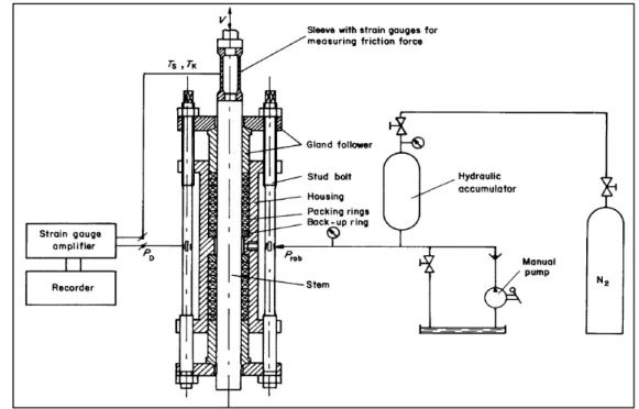
1988) ... 33 Figure 1.19 Test stand for measuring the friction in working condition in a soft
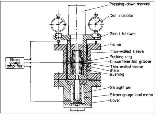
packed stuffing-box (Ochonski, 1988) ... 34 Figure 1.20 Distribution of radial stress at packing-housing and packing-stem ... 35 Figure 1.21 Test apparatus designed by Hayashi and Hirasata (Hyashi and
Hirasata, 1989). 1- Strain gauges, 2- Load Cell, 3- Packing, 4- Load Cell (Pengyun et al., 1998) ... 35 Figure 1.22 Test apparatus designed by Pengyun (1991) for the determination
of internal and external lateral pressure coefficients. 1- Bottom of the stuffing box housing, 2- down pressure sensor, 3- outer measuring ring, 4- packing, 5- gauge, 6- displacement indicator, 7- inner measuring ring, 8- gland, 9- upper pressure sensor, 10 strain gauge amplifier (Pengyun, S. and et al. (1998)). ... 36 Figure 1.23 Internal structure of a sealing ring (Roe and Torrance, 2008) ... 38 Figure 1.24 The stuffing box packing test bench (Diany and Bouzid, 2011) ... 39 Figure 1.25 Test stands used by Grine, (2012) to characterize the porous
parameters of gaskets. (a) UGR and (b) ROTT ... 41 Figure 1.26 Test rigs used to determine the (a) radial and, (b) axial permeability
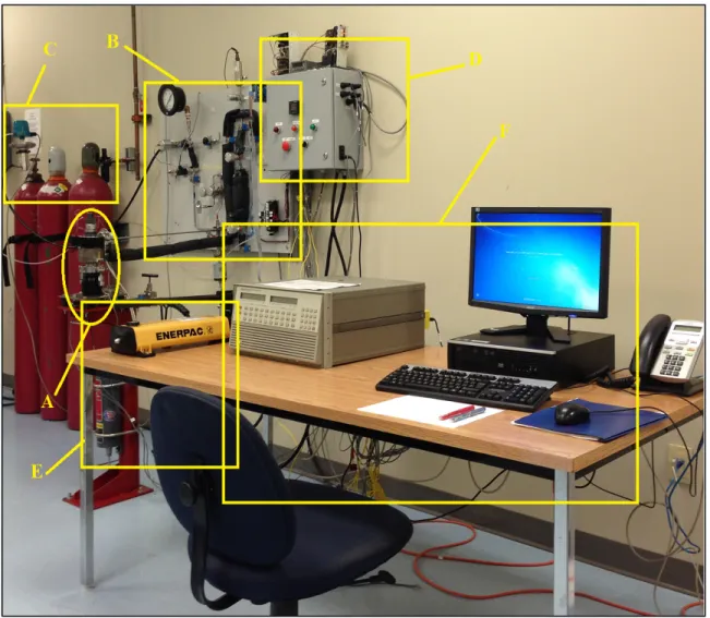
Figure 2.1 General configuration of the test rig used for experimental
investigations (the items are explained in the text) ... 49
Figure 2.2 Packed stuffing-box experimental setup ... 50
Figure 2.3 Displacement measuring mechanism ... 52
Figure 2.4 20 strain gauges attached to the housing external wall ... 53
Figure 2.5 The configuration of high-temperature time-dependent test bench and its components; 1- Strain Gauge, 2- Ring, 3- Base plate, 4- Gland, 5- Bottom Support Disk, 6- Top Support Disk, 7- Washers, 8- Support plate, 9- Spacer Cylinder, 10- Finned Tube, 11- LVDT#1, 12- LVDT#2, 13- Ceramic rod #1, 14- Ceramic rod#2, 15- Hydraulic Tensioner, 16- Hydraulic valve, 17- Pressure Gauge, 18- Packing ring, 19- Nut, 20-Stem, and 21-Spacer Bush, 22- Electrical Oven, and 23- Heater Cover head. ... 54
Figure 2.6 The configuration of high-temperature leak-detection test bench and its components; 24- Gland, 25- Housing, and 26- Spacer ring. Other items are the same in the caption of Figure 2.5. ... 55
Figure 2.7 Pressurization circuit (a) assembly on test bench, (b) the circuit (dotted lines are electrical connections) and (c) the LabView program ... 57
Figure 2.8 The hydraulic circuit ... 58
Figure 2.9 Pressure decay leak measurement system ... 60
Figure 2.10 The pressure rise leak measurement system (a) picture and (b) its circuit ... 61
Figure 2.11 The chart of leak detection technics ... 63
Figure 2.12 The LabView platform to control the packing test rig ... 65
Figure 2.13 A flexible graphite plaited packing ring ... 66
Figure 2.14 A 16-channel module ... 66
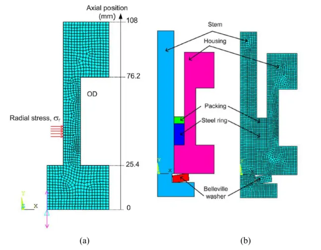
Figure 3.1 Simplified packed stuffing-box with the main components ... 73
Figure 3.2 Stuffing box housing subjected to contact pressure. Dimensions are in millimeters ... 75
Figure 3.4 FE model of the experimental packed stuffing-box ... 82
Figure 3.5 Packed stuffing box test rig ... 84
Figure 3.6 Comparison of Hoop strains at the housing cylinder outside surface for different gland loads ... 85
Figure 3.7 Hoop stress distribution at the housing outer surface. ... 86
Figure 3.8 Longitudinal stress distributions at the housing outer surface ... 87
Figure 3.9 Longitudinal stress distributions at the housing inner surface ... 87
Figure 3.10 Hoop stress distribution at the housing inner surface ... 88
Figure 3.11 Longitudinal stress distribution at the housing inner surface ... 89
Figure 3.12 Hoop strain at the housing inner surface ... 89
Figure 3.13 Radial stress distribution at the housing inner surface ... 90
Figure 4.1 General configuration of a packed stuffing box and the sealant axisymmetric area as 2D domain of porous media with its boundary conditions ... 98
Figure 4.2 General configuration of the test bench ... 100
Figure 4.3 Leak rate versus gas inlet pressure for helium, argon ... 101
Figure 4.4 Apparent permeability for helium, nitrogen and argon at different gland stress levels ... 102
Figure 4.5 Intrinsic permeability versus gland stress for Helium, Argon and Nitrogen. ... 103
Figure 4.6 Diffusivity parameter versus inverse of mean pressure using helium as reference gas ... 104
Figure 4.7 Measured and predicted leak rate with helium ... 106
Figure 4.8 Measured and predicted leak rate with nitrogen ... 107
Figure 4.9 Measured and predicted leak rate with argon ... 107
Figure 5.1 Simplified packed stuffing-box with the main components ... 114
Figure 5.2 packing ring models (a) capillary model, (b) concentric cylinders model, and (c) disordered porosity with modified Darcy model ... 114
Figure 5.3 General configuration of the test bench ... 119 Figure 5.4 Leak rates for flexible graphite packing rings for different gases ... 120 Figure 5.5 Porosity parameters of capillary and concentric cylinder models,
and , versus the reciprocal pressure ratio; (a) = 6.9 , (b) = 13.8 , (c) = 27.6 and (d) = 41.4 ... 123 Figure 5.6 Apparent permeability versus inverse of mean gas pressure for
helium ... 124 Figure 5.7 Diffusivity parameter versus gland ... 125 Figure 5.9 Prediction and measured leak rates for argon vs gland stresses at
different gas pressures ... 127 Figure 5.10 Standard deviation for nitrogen and argon ... 128 Figure 5.11 Prediction and measured leak rates for nitrogen versus gland
stresses at different gas pressures ... 128 Figure 6.1 Sectional view of the packed stuffing-box configuration with a
linearly varying gap ... 135 Figure 6.2 Process of gap filling by expansion of the packing ring due to axial
compression; a) application of stress to fill in the gap at the external wall, while creating one at the inside diameter and b) additional stress to produce contact at the internal wall ... 137 Figure 6.3 FE model of a packed stuffing box with a tapered
housing ... Err eur ! Signet non défini.
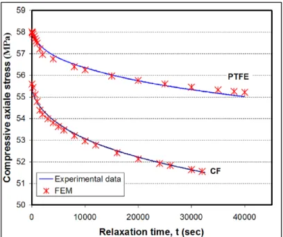
Figure 6.4 Effect of tapered housing on the axial stress distribution with 6 FG packing rings ... 142 Figure 6.5 Effect of tapered housing on the axial stress distribution with 6 PTFE
packing rings ... 142 Figure 6.6 Minimum axial stress in the bottom PTFE packing ring for a 50 MPa
gland stress versus housing taper angle ... 143 Figure 6.7 Minimum axial stress in the bottom FG packing ring for a ... 144 Figure 6.8 Required gland stress to achieve a threshold axial stress of 20 MPa
Figure 6.9 Required gland stress to achieve a threshold axial stress,of 20 MPa in the bottom PTFE packing ring ... 145 Figure 7.1 Simplified packed stuffing-box with the main components at
axisymmetric view. ... 149 Figure 7.2 Detail configuration of test stand... 153 Figure 7.3 The configuration of test setup; 1- Strain Gauge, 2- Ring, 3- Base
plate, 4- Gland, 5- Bottom Support Disk, 6- Top Support Disk, 7- Washers, 8- Support plate, 9- Spacer Cylinder, 10- Finned Tube, 11- LVDT#1, 12- LVDT#2, 13- Ceramic rod #1, 14- Ceramic rod#2, 15- Hydraulic Tensioner, 16- Hydraulic valve, 17- Pressure Gauge ... 157 Figure 7.4 The sectional view of the test bench. ... .
Other components are mentioned in the caption of Figure 7.3. ... 157 Figure 7.5 Relaxation of axial packing stresses ... 158 Figure 7.6 Hoop strain at ring OD versus time ... 159 Figure 7.7 Axial compression of packing ring versus time ... 160 Figure 7.8 Lateral pressure coefficient versus time ... 160 Figure 7.9 Bulk modulus versus time ... 162 Figure 7.10 Shear modulus versus time ... 162
LIST OF ABREVIATIONS ANSI American National Standard Institute AlTin Chromium Nitride
API American Petroleum Institute
ASME American Society of Mechanical Engineering
CA Compressed Asbestos
CF Carbon Fiber
EPA United States Environmental Protection Agency ESA European Sealing Association
FCI Fluid Controls Institute FSA Fluid Sealing Association FEM Finite Element Method
FG Flexible Graphite
FSA Fluid Sealing Association
GHG Greenhouse Gases
IED Industrial Emission Directive ISA International Society of Automation ISO International Standard Organization LMF Laminar Molecular Flow
LVDT Linear Variable Differential Transformer ppmv Parts per million by volume
PTFE Polytetrafluoroethylene PVP Pressure Vessel and Piping PVT Pressure Vessel Technology
ROTT Room temperature Operational Tightness Test UGR Universal Gasket Ring
US United States (of America)
VDI The Association of German Engineers (In German) VOC Volatile Organic Compounds
LIST OF SYMBOLS AND UNITS OF MEASUREMENTS MASS
Milligram Kg Kilogram
Mt Megatons g/mol Molecular Weight
MASS RATE
ppmv Particle per million by volume ppm Parts per million
mg. s Milligram per second / Milligram per second
/( ) Milligram per second per meter / Liters per second
/ Milliliters per second ANGL Deg Degree Rad Radian Length/Displacement Meter milimeters Micro strain in Inches TEMPERATURE C Centigrade F Fahrenheit K Kelvin TIME S Second H Hours Pressure/Stress
MPa Mega Pascal GPa Giga Pascal Bars Bars (0.1 MPa)
INTRODUCTION
Valves are the most common equipment in process plants and systems. They are extensively used to control fluid circulation in the nuclear, chemical and petrochemical process plant. Although a variety of valves exist in industry, the external sealing mechanisms of the valves are composed of almost the same parts as illustrated in the Figure 0.1. In general they can fulfill two sealing tasks; the first one, known as internal sealing, is related to the control of the fluid flow including shut-off. The second one, known as external sealing, is related to the control of the fluid leakage to the outside boundary of the valve system.
Generally, the performance of the internal sealing is determined by the quality of the disk and seat interface. The level of valve external sealing, which is the scope of this thesis, is controlled by the packing material and the amount of radial contact pressures at the interface between the
Figure 0.1 Some basic parts in a valve (CRANE CPE)
packing and side walls. The material resistance and sealing performance of the packed stuffing-box, including yarned packings, are the two most important qualities required for the proper function of valves.
Any flaw in the performance of a valve might have a significant impact. Accidents, shut-downs, loss of revenues, health and safety issues and environmental disasters are to name a few. Despite the long and extensive use of packed stuffing boxes to seal valves, there is not a standard design procedure and standard test procedures to qualify packings (Diany and Bouzid, 2009(a)). With the recent environmental protection laws and the strict regulations on fugitive emissions, attention has focused on the development of new packing products that would meet these requirements in the short and long term.
These restrictions imposed to the industries are aimed at reducing the amount of fugitive harmful gases and liquids. Climate change is considered as one of the most important environmental concerns. Scientific studies revealed that the global warming is attributed largely to human activities in relation to the amount of greenhouse gases and their release to the atmosphere.
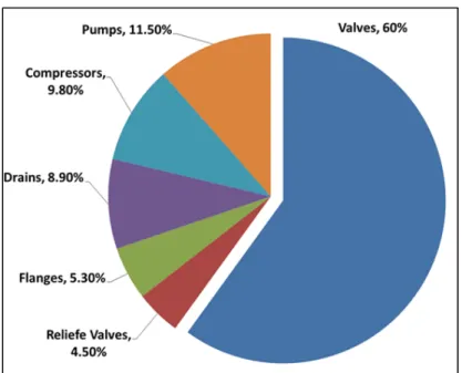
For example the GHG emissions emitted by oil and gas production, including production, transmission, processing, refining and distribution industries that are major users of bolted joints and industrial valves, were 163 megatons (Mt) in 2011 in Canada. This amount was the second-largest contributor of pollution sources (Environment Canada, 2013). Another similar study conducted by the Environmental Protection Agency of the United State (EPA) gives the percentage of fugitive emission contribution of each equipment type. The results which are shown in Figure 0.2 illustrate that bolted joints and valves contribute almost 66 % of the major pressure vessel components in plants. 90% of these are valves with stuffing-box packing. Close to 60% of all fugitive emissions comes from valve leaks and packed stuffing-box failures (Hoyes, J.R. and Thorpe, L.C., 1995).
Following the above mentioned alarming statistics, new environmental regulations and standards have been legislated to improve the leakage performance of these equipment. In 2009 and based on the Copenhagen accord, some industrialized countries, including Canada, have been targeted to scale down the amount of GHG production to a safer level (UNFCCC, 2009). In Europe, the German standard for control of air pollution, TA-Luft, is devoted to the reduction of the emission from gasket joint systems with application to chemical and petrochemical industries (TA-Luft, 2002). TA-Luft determines the quality of sealing and permissible leakage. The instructions for shut-down and regulation of the valves are referred in VDI 2440 (2000).
In the US, which is one the main industrialized countries and the second largest producer of GHGs, a number of authorized test methods to qualify the sealing performance of equipment exist. Some are standards and others are in-house test procedures. For the valve test methods such as ISO 15848-1, for the process valve packing API 622; for the packings in refinery equipment the Chevron Texaco GR-500 App. V; for the industrial valves the SHELL, MESC SPE 77/300 (2008) permission test; for the external leakage of on-off valve the ISA/ANSI 93.00.01 and for the sealing of the stem in control valves FCI-91-1-1997 are the most applied test procedure.
Figure 0.2 Typical distribution of fugitive emission sources in a refineries by EPA
With consideration to the sealing performance significance of a valve’s external sealing, a proper study is required to accord the quality of packed stuffing-boxes with the new regulations. The primary step required to achieve this target is the furthering of existing comprehension on the integrity of components in stuffing-boxes and their effect on sealing performance. This study is focused on this aspect, with two main objectives; to firstly model the mechanical integrity of the elements in stuffing-boxes and to secondly characterize the sealing behavior of these components.
The safe operation of industrial plants is dependent on the adequate function and tightness performance of bolted flanged joints and valves (Klenk et al., 1999). Considering the sealing process of valves, stuffing-box packings are of great importance. For the development of a suitable design for packed stuffing-boxes, a proper understanding of the different properties of the packing material is crucial. For example, lateral pressure coefficients, stiffness, creep, relaxation, friction, wear and tightness of the packing rings have major impacts on sealing performance. A more accurate and realistic model that takes into account the aforementioned parameters would be very useful in providing a comprehensive design procedure for valves. Along with these parameters that affect valve performance, this study investigates the contact stress distribution and the characteristics of the porosity in packing materials. These two influential parameters and their interconnection with other parameters are important in the prediction of leakage in packed stuffing-boxes and can be used to quantify performance and develop improvements to sealing quality.
The first objective stems from the need to address the mechanical integrity of a large class of valve stuffing-boxes which involve the modeling of sealing contact stress distribution between packing rings and side walls. Given its industrial significance, the determination of the contact stress distribution has been the object of much research. In the literature, several models have been proposed to predict contact pressure distribution during initial tightening. However, there does not exist a comprehensive model capable of determining the mechanical integrity of packed stuffing-boxes. Furthermore, the elastic interactions of the different elements of stuffing-box packings and their behavior with temperature have not yet been accurately
simulated. In addition, experimental results have not been reproduced analytically or numerically because of a lack of data for the properties of packing materials.
The second objective arises from the lack of a rigorous constitutive model adequate for the modeling of the leak behavior of stuffing-box packings. This objective aims to develop a process that can be exploited to determine the leak property of porous materials used as a seal in stuffing-boxes. A variety of materials are used for this purpose, such as Teflon, flexible graphite, fiber based, plated fabrics, or a combination thereof. The most significant and common property between these materials is their lateral pressure ratio. Although this property is counted as an advantage in the transfer of axial load to the contact side walls, the problem is the porosity that allows for high pressure gases or fluids to escape outside of the valves. A rigorous methodology has been planned to fulfill the objectives of this study, which must meet certain requirements in order to cover all aspects of packed stuffing-boxes. First, there is a focus on the ability to handle the broadest range of shapes and materials for stuffing-boxes. This ability is what leads to the presentation of a comprehensive model that can be exploited to develop standard design procedures. The second requirement is the robustness of the proposed method in the evaluation and assessment of the presented models. This requirement arises from the need to clarify the effect of selected parameters on the sealing performance among which are the geometrical, physical and material complexities. Finally, this methodology must be repeatable with standard tools. The second requirement necessitates the presentation of a model that can be proposed and guarantee that the results are directly applicable to various circumstances.
A combination of analytical, experimental and numerical investigation techniques were used to meet the requirements of a comprehensive study. The analytical modeling in this study is based on the firm physical laws that dictate how to construct a model capable of describing the behavior of each component. In consideration of the complexity of the interactions between parameters and their effect on sealing performance, empirical terms are used in the analytical models. An extensive experimental plan has been conducted to investigate the value of the empirical parameters. In addition to the abovementioned purpose, the experimental studies were targeted toward the evaluation of the presented models. The studies were carried out on
a well-equipped test bench that had been modified in the laboratory of static and dynamic sealing at the École de Technologie Supérieure. It should be emphasized that the experimental set-up and the measuring devices adjusted on the experimental test bench are clearly described and obtained from standard equipment. The accessibility of the experimental set-up allows for the creation of an experimental procedure that is repeatable and extendable to other working environments.
For many engineers and researchers, there is limited access to such standards on which to conduct their evaluations and further their investigations. Therefore, the methodology is also limited to numerical simulations that can be carried out with standard commercial Finite Element Method software (FEM). The advantages of FEM investigations are that it is possible to verify the presented model faster and much less expensive than experimental investigations, while also applying to many situations and practical applications where conducting an accurate experimental investigation would not be possible.
This thesis is presented in seven chapters. The first chapter presents a general literature review on packed stuffing-boxes and some related aspects such as bolted joints and creep behavior, in addition to reviews of the common domains of interest in which engineers and researchers have conducted investigations with similar objectives. Gasket bolted joints, flow in porous media, and numerical simulations for elastic interactions are to name a few.
Since in this study it is intended to use the results from an experimental investigation for the verification and characterization of the presented model, it is necessary to set up a test stand that is capable of demonstrating the real behavior. Thus, the second chapter is entirely devoted to the description of the experimental set up and the procedures for measuring the targeted parameters. Few researchers have developed test benches and investigated few parameters that affect the sealing performance of packed stuffing-boxes. Such investigated parameters are gland pressure, packing material, temperature effect, and the type of gas. The test stand used in this study was developed for the purpose of measuring the parameters related to the objectives of this study.
In the third chapter, a structural integrity study of the valve housing is conducted in order its influence on the contact stress and packing ring leakage behaviour. This part of the study was presented at the American Society of Mechanical Engineering Pressure Vessel and Piping conference (ASME-PVP 2014) in the Ph.D. category of the student paper competition. An extended version of this paper was published in the ASME Journal of Pressure Vessel Technology in 2015 (Kazeminia and Bouzid, 2015). The objective of this study was to provide a basis for a standard design procedure of packed stuffing boxes such as the already existing one on bolted flange connections in the ASME Boiler and Pressure Vessel Code.
The second objective of this thesis is treated in chapters four, six and seven. In the fourth chapter, a new approach to characterize micro- and nano- flows through the porous structure of packing rings is presented. The porosity parameters are defined using a developed pseudo analytical-experimental procedure. The obtained model is used to predict the leak rate through packing rings. The effect of packing compression and gas pressure; two important parameters in the prediction of leak rates were investigated. A paper dedicated to this study was presented at the American Society of Mechanical Engineering Pressure Vessel and Piping conference, in 2015 in Boston. An extended version with additional results was published in the journal of Pressure Vessel Technology (Kazeminia and Bouzid, 2016).
In the fifth chapter a comparative study between different fluid flow models is presented. The capillary and concentric cylinder models with first order slip models were compared to a modified Darcy model adapted for compressed packing materials. In this study the accuracy of these models and their ability to predict leak were tested by comparison with experimental measurements. The results of this study have been the subject of a paper submitted to the Elsevier International Journal of Pressure Vessel and Piping.
In the sixth chapter, presents an article entitled “Effect of Tapered Housing on the axial Stress Distribution in a Stuffing-Box Packing”, which has already been published in the International Journal of Advancement in Mechanical and Aeronautical Engineering (Kazeminia and Bouzid, 2014). This paper provides a comprehensive study on the radial stress distribution in a set of packing rings. Two presented models are proposed to increase the sealing performance of
packed stuffing-boxes. The two models are supported analytically and numerically to demonstrate an improvement of leak performance.
In the last chapter or chapter seven, the time-dependent behaviour of a flexible graphite based packing ring is presented. This study which is carried on a modified high temperature test bench, demonstrates the simultaneous effect of creep and relaxation present in packed stuffing boxes. The results of this study has been published in the proceeding of the ASME pressure vessel and piping conference (Kazeminia and Bouzid, 2016).
This thesis concludes with a general conclusion of the work conducted during the course of this Ph.D in addition to few recommendations that are suggested for future work.
CHAPITRE 1 LITERATURE REVIEW 1.1 Introduction
Although packed stuffing boxes have been used for decades in the sealing of valves and pumps, there is no standard methodology that could be useful to design these assemblies. In addition proper tools to select the right packing suitable for a certain application do not exist. It is only recently that few standard test procedures have been suggested. These test procedures are designed to qualify the sealing performance of compressed packings and have recently been adopted in both North America and Europe. Several researchers have developed both analytical and numerical models to simulate the behavior of packed stuffing-boxes. The lack of enough knowledge on material properties of the packed stuffing boxes, the elastic interaction of the different joint elements, and the nonlinear behavior of yarned packings are the main obstacles to overcome in the theoretical studies. Therefore, there is a need to characterize packed stuffing-boxes and validate existing and under development models with experimental studies. The main challenge with latter is to build an instrumented test rig that can capture the real behavior of a packed stuffing box.
For the sake of an inclusive review, this chapter is divided into five subsections. After the introduction in the second part, a general introduction of existing standards and documented codes is presented. Then a review of existing analytical studies of packed stuffing-boxes is presented. The fourth part discusses few numerical finite element models used to simulate the interface contact stresses numerically, and their short term creeps behavior. The fifth part is dedicated to experimental investigations and discusses existing test rigs and test procedures.
1.2 Standards and documented codes
There is no known standard currently in use that provides step-by-step instructions to design packed stuffing boxes and select a suitable packing type for a certain application. Also,
documented standard test procedures related to the qualification of packed stuffing-boxes are only recent. API 622 and ISO 15848 are two recent standards that are undergoing major revisions. Due to the strict legislation on fugitive emissions and the new environmental protection laws, several standard design codes introduce new criteria based on leakage rate while valve systems lack a design methodology.
Fugitive emission requirements are one of the critical regulations that the chemical and petrochemical industries have to comply with. The motivation to develop new standards is ever increasing to maintain a clean environment. In North America, manufacturers have a great concern about qualification and certification of their valve products and, in particular, their compliance with the EPA strict regulations about fugitive emissions. In fact, there is a need to develop new standards related to the design and testing of valve stem packing because these components are the main source of fugitive emissions of pressurized equipment (FSA, Sealing Sense (2012)). Some important standards and in-house test procedures related to valve fugitive emissions developed after the 90’s are ISO-15848-1 and -2, API-622, API-624, ANSI/ISA S93.00.01, ANSI/FCI 91-1, TA-Luft VDI 2440, SHELL MESC SPE 77/300, SHELL MESC SPE 77/312, Chevron SSM-PU-53.02-A and EXXONMOBIL GP 03-12-09.
The ISO-15848 standard for valve fugitive emissions has been issued by International Standards Organization (ISO) in two parts using a wide range of information from different industries (FSA, Sealing Sense (2012)). The first part, ISO-15848-1 (ISO 15848-1 (2006)), imposes helium or methane as a test media and a sample of a test rig that performs such a test is shown in Figure1.1 (c). The test leak detection method used is the one referred as EPA1 method 21 for leak
measurements of the completely assembled valves to address a classification system and
qualification procedure. The range of temperature is between -1960Cto 4000C (-320.8Fto 752F),
and the criteria for the leakage failure is a predetermined parameter specified by the customer. Table 1.5 Average gaseous emissions (leakage) and valve
gaskets (Heymanns Verlag, C. (2002))
Table 1.6 Average gaseous emissions (leakage) and valve gaskets (Heymanns Verlag, C. (2002))
Gasket system
Leakage related to the average size of the gasket [mg/(s
x m)] Stuffing box with packing 1.0 Stuffing box with cup leather,
O-ring 0.1
Stuffing box with packing, stuffing box with cup leather, O-Ring (with "TA Air Certificate" according to
VDI 2440, Section 3.3.1.3)
0.01
Metallic bellows, sealed 0.01 Metallic bellows, sealed (with flat
gasket possessing a TA Luft Certificate according to VDI 2440)
0.001 Stuffing box with packing and
sealing medium/suction, metallic bellows, welded on both sides
No emission proof
Table 1.7 Average gaseous emissions (leakage) and valve gaskets (Heymanns Verlag, C. (2002))Table 1.8 Average
(a)
(b)
(c)
Figure 1.1 Test device for (a) API-622, (b) API-624 and (c) ISO (FSA, Sealing Sense (2012))
The second part of ISO standards for valve fugitive emissions, ISO-15848-2 (ISO 15848-2 (2003)), is a quality control test or a production acceptance test of valves. This part ensures the production quality of the valves tested in part one and defines a quality control test method to be followed systematically in the manufacturer’s site. The recommended testing fluid is helium, and the test should be conducted at a pressure of 6 bars and is supposed to run at room temperature. Also, this document should indicate the percentage of the total produced valves for inspection. Presently both parts of this standard are under revision.
The American Petroleum Industries (API) issued two standards for valve fugitive emissions. The first one is API-622 (API-622 (2011)), the second edition of which has been published in 2011. In addition to the use a specific test rig for fugitive emission testing of valve packings described in the first edition, it is now permitted to test an assembled valve system instead. The test bench shown in Figure 1.1(a) uses methane as the testing fluid and the procedure imposes five thermal cycles from ambient temperature to 260oC (500F) and 1510 mechanical cycles
representing the opening and closing of the valve. Also, this standard considers corrosion of the packing material and defines a criterion of 15 percent oxidation in 24 hours as per the procedure of FSA2-G-604-07, method B. Furthermore this standard limits leakage failure to
500 particles per millions (ppm) as imposed by the EPA.
The second API standard for valve fugitive emissions is API-624 (API-624 (2011)) which is devoted to rotating and rising-rotating stem valves (test bench in Figure 1.1(b)). This document defines the required test procedure and imposes methane as testing fluid while referring to EPA method 21 for leak measurements and setting the limit to 100 ppm. The allowed temperature range is -29 oC to 538 oC (-20F to 1000F). The test procedure requires 310 mechanical cycles
and three thermal cycles. Similar to ISO-15848-1, the sealing materials must be photographed after valve system disassembly to record any surface changes that can affect the sealing performance.
The American National Standard Institute (ANSI) has issued a standard test procedure entitled “standard method for evaluation of external leakage of manual and automated on-off valves” with identification number ANSI/ISA-93.00.01-1999 (ANSI/ISA-93.00.01 (1999)). This standard applies to the classification of valve design and determines the procedure for testing of valve stems and body seals but cannot apply for production testing and quality control of valves. Similar to other standards, the purpose of this standard is to establish a unified procedure to test the compliance of the seal according to volatile organic compounds (VOC) fugitive emission requirements. The test procedure can be conducted under one of the four different predefined temperatures, -46 oC (-50F), ambient, 177 oC(377F) and 399 oC(750F).
All tests except the one conducted at ambient temperature must include at least one thermal cycle.
ANSI issued another most recent standard for qualification of stem seals of the control valves in collaboration with the Fluid Control Institute (FCI). The identification number of this standard is ANSI/FCI 91-1-2010, which was originally an FCI standard released in 1991. After several revisions, in 2010, it was adopted by ANSI as a voluntary standard. By considering the ability of packing seals to withstand mechanical and thermal cycles under a predetermined pressure and temperature conditions, this standard classifies the stem seals of the control valves. It mentions that the results from the test conducted using this standard procedure could be used to predict the leakage of a valve that operates at the same temperature and pressure conditions. The number of mechanical cycles defined for valve operation from fully open to fully closed and back to fully open is between 25000 to 100000. Two allowable leak rate levels are defined; the first one is up to 100 ppmv and the second one is up to 500 ppmv.
In Germany and some other European countries, the TA-Luft is a well-known adopted standard for stem sealing (ISO 15848 / TA-Luft (2012)). For the purpose of reduction of fugitive emissions, a guideline has been provided in compliance with allowable leakage and defines regulations for inspection according to VDI4 2440 (Riedl, 2007). In this standard, known as TA-Luft/VDI 2440, the average leakage of different gasket sealing systems are referred to VDI 2440 which is illustrated in Table 1.1. The testing fluids are helium and methane with the possibility of running the test at a specified temperature.
In addition to the standards mentioned above, there are some other in-house tests (SHELL MESC SPE 77/300, SHELL MESC SPE 77/312, Chevron SSM-PU-53.02-A and EXXONMOBIL GP 03-12-09) which are developed to evaluate the qualification of a valve sealing performance with a fugitive emission criteria agreed upon prior to testing. Although all standards related to valve fugitive emissions have almost similar objectives, they use different leak measuring methods, fluid, temperature, pressure, the number of mechanical and thermal cycles and so on. In spite of all these standards, the lack of a comprehensive design procedure of valve sealing system is still obvious.
1.3 Analytical studies
In general, there are two ways for a high-pressure fluid inside the valve to escape out from packed stuffing boxes and bolted gasketed joints. The first one is a surface leak that exists at the interface between packing rings and side walls formed by the housing and stem. The second one is through the porous structure of the packing materials. Unfortunately, there are limited
Table 1.1 Average gaseous emissions (leakage) and valve gaskets (Heymanns Verlag, C. (2002))
Gasket system
Leakage related to the average size
of the gasket [mg/(s x m)]
Stuffing box with packing 1.0
Stuffing box with cup leather, O-ring 0.1 Stuffing box with packing, stuffing box with
cup leather, O-Ring (with "TA Air Certificate" according to VDI 2440, Section 3.3.1.3)
0.01
Metallic bellows, sealed 0.01
Metallic bellows, sealed (with flat gasket possessing a TA Luft Certificate according to
VDI 2440)
0.001 Stuffing box with packing and sealing
medium/suction, metallic bellows, welded on both sides
studies in the literature that accurately distinguished the amount of leak produced by each type of leak with gaskets and packing made of soft materials. Nevertheless, it is recognized that leaks through the pores are more important than the surface leaks with soft materials used with smooth surface finish (Arghavani et al., 2002). This second source of leak depends on the structure complexity, size and amount of pores inside the packing materials. In the former source, the amount of leak depends on the ability of the assembly to maintain a minimum threshold contact pressure between the mating surfaces and surface roughness under the operating conditions of pressure and temperature.
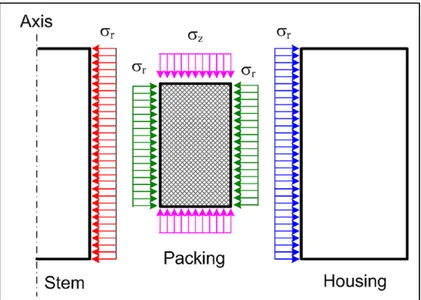
In contrast to the leak through the pores of packing materials, there is little focus on the contact stress between the packing rings and side walls. A radial contact pressure distribution is developed as a result of axial compression provided by the gland, as illustrated in Figure 1.2
Figure 1.2 A schematic sample of industrial valve with stuffing-box packing ( ISO 15848 / TA-Luft, 2012)
Figure 1.3 Sectional view of packed stuffing-box (Diany and Bouzid, 2006)
and Figure 1.3. Based on this concept, Denny (Denny, 1957) proposed the use of a lateral pressure coefficient defined as the ratio between the radial to axial stresses:
=
(1.1) Where and are axial gland stress and radial contact stress respectively. He also found that the radial stress is constant once a minimum amount of axial stress is reached for a particular packing material.
Based on a rigorous analysis and depending on the internal or external friction coefficient between the packing and the stem or housing, one can distinguish two lateral pressure coefficients; an internal and an external lateral coefficients and which are discussed in the literature.
Based on the free body diagram of Figure 1.4 and the boundary conditions, Ochonski (Ochonski, 1988) proposed a formulation that describes the radial contact stress distribution along the stem. His proposed analytical model describes the behavior of soft-packed stuffing-boxes and is supported by experimental results. His analysis leads to, the axial stress distribution given by the following expression:
(a) (b)
Figure 1.4 Forces acting on a packing element, (a) General model and (b) Simplified model (Pengyun et al., 1998)
= (1.2-a) Where is the axial position starting from the contact surface between gland and packing and
is defined as
= 4 +
− (1.2-b)
Where , , and are friction coefficients, lateral pressure coefficients, internal and external packing diameters, respectively, and the subscripts i and e refer to internal and external contact surfaces.
An exponential distribution of the radial contact stress is also obtained by solving the derived differential equation obtained from the force and moment balance based on a free body diagram similar to the one in Figure 1.4 (a) with the assumption that the concentrated force acts in the middle of packing elements in the radial direction. With this analytical model and the experimental measurements of the housing deformation, they obtained a relationship between the radial and axial stresses.
Considering a similar model to the one shown in Figure 1.4(b) and assuming the force distributed uniformly in the radial direction, Pengyun et al. (Pengyun et al., 1998) found a new expression for the distribution of the axial stress. Applying equilibrium of forces acting at the mid packing width and moments around the stem axis they derived the expression for the distribution of axial stress such that
= (1.3-a)
= 16 ( −
− )
(1.3-b)
Imposing the assumption of analogous conditions to the two contact boundaries and equating the lateral pressure coefficients and friction ratios, the parameter can be reduced to
= −16
− = −8 (1.4)
Where is the wideness of the packing ring. The model described by equation (1.4) was first suggested by Denny and Turnbull (Denny and Turnnbull, 1960). Pengyun and et al. (1998) evaluated the applicability of the assumption of the analogous conditions at the two contact boundaries. They proposed that their model described by equation (1.3) should give the same distribution of axial stress as in equation (1.2) and consequently the following relationship is deduced = 3 + 5 5 + 3 (1.5) or = 1 + 2 4 + 3 4 + 5 (1.6)
This formula gives the ratio of internal to external lateral pressure coefficients as a function of dimensions and friction coefficient ratios.
Dianny and Bouzid (Diany and Bouzid, 2006) presented a more rigorous model that gives the axial stress distribution and determined a new parameter used in equations (1.2) and (1.3). Considering the free body diagram presented in Figure 1.5, and by taking the moment about the axis and considering the infinitesimal moment force, they determined that
= (1.7-a)
= 24 ( −
− )
(1.7-b)
By comparing equations (1.2-a) and (1.3-a), a relationship that expresses the lateral pressure ratio as a function of friction and geometry is obtained such that
= 1 + 2 5 + 7
7 + 5 (1.8)
The flexibility of the stem and housing is an important factor to consider when simulating the real behavior of a packed stuffing box. The interaction of the packed stuffing box elements was studied by Diany and Bouzid (Diany and Bouzid, 2009(a)). Based on the free body diagram and the flexibility of the different elements of the stuffing-box, as illustrated in Figure 1.6, together with an analysis of compatibility conditions between the packing and side walls have led to the evaluation of the internal and external lateral pressure coefficients independently. They found that these coefficients are material and geometry dependent and made comparisons with other similar results in the literature.
In addition to the surface leak produced at the interface between packing and side walls, there is a possibility of leakage failure through the porous material of packings. Hisaro and Yoshida (Hisao and Yoshida, 1991) conducted an experimental study on stuffing-box packing tightness performance by measuring the total leakage. The main parameters of their study were the total packing height, the packing compressive stress and fluid pressure. They tested two types of packing materials: Asbestos and flexible graphite packing rings.
The initial tightening of a packing set, which generates the required contact pressure to seal, decreases with time due to the creep-relaxation of the packing material. This fact has fostered researchers to study this phenomenon for the purpose of predicting the contact pressure drop and its influence on leakage. Tashiro and Yoshida (Tashiro and Yoshida, 1991) investigated the stress relaxation of gland packings. They have developed a theoretical model that was supported experimentally with test data. The tested packing rings made of asbestos and graphite and modeled as viscoelastic materials describe potentially their relaxation behavior. The main focus of another study conducted by Diany and Bouzid (Diany and Bouzid, 2012) was the short-term relaxation of packing rings. Their developed analytical model, based on the Maxwell generalized model as illustrated in Figure 1.7, relies on the relaxation modulus of the packing material to predict relaxation. Eight Prony series model the viscoelastic behavior of the packing elements that the required coefficients of which are obtained from material data available in the literature.
With the lack of creep data and creep models, the creep constitutive law of packing materials was investigated by Diany and Bouzid (Diany and Bouzid, 2012). Based on relaxation tests, the packing materials are assumed to have linear viscoelastic behavior and relaxation was
Figure 1.6 Free body diagram of elements in a stuffing-box packing (Diany and Bouzid, 2009(a))
studied in the time domain using stress-strain relations in integral form. Experimental and numerical studies supported the validity of the developed analytical model.
After some preliminary progress in the modeling and characterization of stuffing box packing, researchers decided to treat more complex applications. Li and his colleagues (Li et al, 2012) studied the failure of a packed stuffing box used in a high-pressure compressor. With the help of a theoretical model and experimental observations, they investigated the reasons for cracks in the stuffing-box packing subjected to very high pressure.
Since late 1980’s the fluid flow through nano and micro-porous media became a popular research topic due to its important application in science and engineering such as the micro electro mechanical system fabrication technologies and biomedical chip systems (Karniadakis et al., 2000). Fluid flow through porous media became an important subject in engineering applications such as in oil and gas (Kfoury et al., 2005; Espinosa-Paredes, 2015; Lotfizadeh and Matsoukas, 2015), and, gas separations (Liang and Weimer, 2015; Jiang et al., 2009). The mechanism of fluid and gas transportation inside the porous media mostly depends on the relative size of the pores and the mean free path of the fluid. The mean free path is the average distance between molecules of a liquid or gas after a collision (Karniadakis et al., 2000). Knudsen number is a parameter used to quantify this variation and is defined as the ratio between mean free path and hydraulic diameter, such that
=
(1.9) For ≤ 0.001, the fluid regime is continuous and Navier-Stockes equations may be used to describe fluid flow and boundary conditions. When 0.001 ≤ ≤ 0.1 a slip flow regime is present where the number of collisions between molecules and the wall are more important than the collisions between the molecules. In this case, the Navier-Stockes equations may be used to describe the fluid flow with slip boundary conditions. The flow regime is transitional when 0.1 ≤ ≤ 10 in which the various moment methods may be applied to describe fluid flow. For ≥ 10, a free molecular regime is present and Boltzmann equations can be used to describe the fluid flow.
Applications, such as bolted flange joints, have been the subject of more investigations in relation to fluid flow through porous gasket materials. Jolly and Marchand (2009) used Darcy’s model with the first order slip condition to estimate leak through an annular gaskets. They assumed that the gasket is made of several parallel disks distributed through the thickness. The flow of gaseous fluid is assumed in the radial direction taking into account gas compressibility. Following their studies, Marchand et al. (2005) determined that the type of the regime with some gasket materials is not only Laminar but intermediate and or early molecular. Hence, to consider the effect of rarefactions, they applied the filtration velocity with intrinsic permeability and Klinkenberg’s Effect on the Navier-Stokes equations in the cylindrical coordinate. The applied first order slip condition at the wall of the channel is
=2 − (1.10)
They used Helium and Argon as reference gasses and two types of gaskets made from flexible graphite (FG) and compressed asbestos (CA). The results of this model presented almost the same accuracy as laminar-molecular flow (LMF). They suggested that using this model would allow the introduction of more characteristics such as intrinsic permeability and Klinkenberg’s number. Without characterization of the gas type, they compare the results for the prediction
of SF6 and CH4 leak rates. They noted that using Argon as a reference gas gives more accurate
predictions while Helium tend to oversee the leaks.
Grine (Grine, 2012) studied the micro and nano flow through gaskets in bolted joints in his doctorate thesis. He presented an innovative approach to predict leak rates in gasketed joints subjected to different contact stresses, gas pressure and gas type (Grine and Bouzid, 2011). Through their microscopic approach, they characterized the porous properties of the gaskets by determining the number of the micro or nanochannels and their diameter. As a sealant, the PTFE based gasket was the porous media while Helium was used as the reference gas to determine the characteristics of the pores. The results are then used to predict the gas leak rates for the cases with different gasses.
The capillary and annular models that divide the porous media into micro-channels and parallel plates are applied in the studies of Lassaeux et al. (Lassaeux et al. 2011) see Figure 1.8. They concluded that for the leak rates in the range of 10-4 liter per second, the slip flow model
presents better agreements with experimental data while for the range of 10-6 liter per second
the molecular model is more accurate. Also, they determined that using these approaches for increased gasket compression presents a reduction in the thickness of the micro and nano channels while the number of paths remains relatively constant.
In another study, Grine and Bouzid (2010) considered the flow of liquids through micro and nano channels of graphite-based gaskets, where they proposed the capillary model with water and kerosene, and compared the results of theoretical models to ones obtained through
(a) (b)
Figure 1.8 Macroscopic models to study the characteristics of porous media (a) Capillary Model, and (b) the Annular Model (Grine and Bouzid, 2011)
experimental investigations. They exposed very promising arguments, although some discrepancies in their interpretation of interfacial flow at low pressures was not taken into account in their capillary model.
The previous study was further enriched through the analysis of high-temperature operational conditions (Grine and Bouzid, 2013). Two objectives were considered in this study: leak rate at high temperatures and the correlation between the displacement of the gaskets and the porous characteristics. The parameters relative to the pore characteristics are the number of micro and nano channels and their thickness. The capillary slip model was used as the analytical approach, with the results being comparable with ones obtained from experimental investigations using helium and nitrogen at a leak rate range of 10-4 liter per second. The results
showed a decrease of leak rate with a temperature increase. A possible justification for this phenomenon is the fact that increasing temperature soften the gasket causing an increase in compression and hence a decrease in the diameter of the micro- and nano-channels.
Few papers cover the characterization and prediction of the fluid flow of the porous media used in the valve stuffing boxes. For example, Tashiro and Yoshida (1991) conducted an experimental investigation on leakage through the pores of packed stuffing boxes. They used water as the liquid inside the valve and two types of packing rings made from asbestos and graphite materials. The main aim for their study was to investigate the correlation between leak rate versus packing height, packing compressive stress and fluid pressure.
The permeability of packing rings made from exfoliated graphite was investigated by Lasseux et al. (2011). Because of the high tortuosity of the porous material, they proposed a model based on Klinkenberg’s effect in its flow characterization. They assumed that a compressible ideal gas flows isothermally at a low Reynolds number, so the general form of conservation equation used is:
+ ∇. (ρ V) = 0 (1.11)
= + . ∇
(1.12) They studied the radial and axial values of the permeability and Klinkenberg’s number for a single ring, presented in Figure 1.9. Then, they proposed an experimentally based procedure in concert with the presented theoretical model to determine these parameters.
The results of these studies show that axial permeability is one order of magnitude greater than radial permeability. Furthermore, it was revealed that an increase in compression stress causes a reduction in the permeability, causing a second order correlation, and that Klinkenberg’s effect decreases with permeability.
1.4 Numerical simulations
Computer simulation is a powerful tool in engineering that helps in the analysis of complex structures subjected to any loading condition. Using such tools in engineering processes does have several benefits and drawbacks. In particular, it allows for the analysis of complex and large scale models at low cost when compared to experimental studies. In addition, it allows for the solving of complex problems that are sometimes very difficult or impossible to treat analytically.
Figure 1.9 Annular section of a packing ring (Lassaeux et al., 2011)
However, the ability of commercial software to include all material behaviors is limited, and packing materials happen to fall into this category, therefore, users are cautioned to validate and verify their results.
The packed stuffing box valve configuration has an axis of symmetry which facilitates its simulation. The main obstacle in the numerical simulation of stuffing-box packing is the material modeling of the packing rings and the interaction between the packing ring and the side walls. Several researchers have already proposed different techniques to simulate the housing, stem, gland and packing interactions numerically.
Cartraud and Wielcosz (1996) proposed a model for elastoplastic seal material, including non-linearity. Zerres et al. (1998) compared the mechanical behavior of bolted joints obtained through both FEM analysis and the approach proposed by the European code EN-1591. They reviewed the models using the simplifications introduced by the European code EN (Zerres et al., 1998).
Baogang et al. (1999) conducted a 3D FE model analysis by considering the nonlinearity in the behavior of the gasket. They compared the results of an analysis of several joints with a variety of flange thicknesses, thus showing that the performance of a flange joint sealing is affected by the non-linearity of the stress-strain curve of the gasket.
Sawa et al. (2002) used an elastoplastic model that considered the hysteresis effect and the nonlinear behavior of a spiral wound gasket to study the effect of the nominal diameter of flanges on the distribution of contact stress. They found that the variation in the distribution of the contact stress of bolted joints with large diameters is greater than for those with smaller diameters. This phenomenon can be explained by the difference in the number of bolts and the rotational flexibility of the flange. Thus, when internal pressure is applied to the assembly, they found a reduction in actual sealing surface.
Diany and Bouzid (2006) numerically simulated the mechanical interaction of packed stuffing boxes using ANSYS software. The model is an axisymmetric configuration with four-node plane elements used to model the housing and stem, and 2D four-node hyperelastic elements
to model the packing rings. They used experimental data to describe the nonlinear behavior of packing material during the loading phase. However, the load loss pressure and temperature was not investigated in this study.
In another paper, Diany and Bouzid (2009(a)) exploited a numerical simulation for stuffing-boxes to evaluate their proposed analytical model. The axisymmetric finite element model, illustrated in Figure 1.10, was used to study the effect of applied axial stress on the axial distribution of lateral contact pressure between packing and side walls as a function of the friction coefficient. The packing material was modeled using the Mooney-Rivlin material behavior with the two constants, C1 and C2, determined experimentally by curve fitting. The investigated parameters were the number of packing rings (2 to 8), gland pressure (10 to 50 MPa), and friction coefficient (0.15 to 0.25).
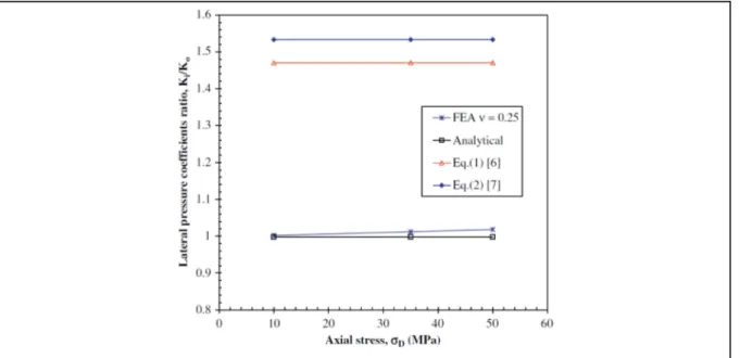
The comparison between the models of equations (1.5), (1.8) and their proposed analytical model, as well as the results from the finite element model are illustrated in Figure 1.11 (Diany and Bouzid, 2009(a)). The results show that the ratio of lateral pressure coefficient is almost independent of the gland pressure, and the analytical results corroborate the results obtained
Figure 1.10 FE model of a stuffing box packing (Diany and Bouzid, 2009(a))
from the finite element analysis. As for the axial stress, the effect of the friction coefficient was found to be less than 10% for a gland stress of 50 MPa. This result, illustrated in Figure 1.12, confirmed that changes in the friction coefficient, within a certain range, does not have a significant effect on the level of the contact stress.
Figure 1.11 The result of lateral pressure coefficient ratio vs gland pressure from (Diany and Bouzid, 2009(a)). Eq.(1) in the figure is Eq. (1.5), Eq.(2) is Eq. (1.8) in the text.
Figure 1.12 The internal lateral pressure coefficient versus number of packing with variable friction ratio (Diany and Bouzid, 2009(a))