UNIVERSITÉ DE MONTRÉAL
LIFT ALTERATION AT LOW ANGLE OF ATTACK USING PLASMA ACTUATION
XIN GU
DÉPARTEMENT DE GÉNIE MÉCANIQUE ÉCOLE POLYTECHNIQUE DE MONTRÉAL
THÈSE PRÉSENTÉE EN VUE DE L’OBTENTION DU DIPLÔME DE PHILOSOPHIAE DOCTOR
(GÉNIE MÉCANIQUE) DÉCEMBRE 2017
UNIVERSITÉ DE MONTRÉAL
ÉCOLE POLYTECHNIQUE DE MONTRÉAL
Cette thèse intitulée :
LIFT ALTERATION AT LOW ANGLE OF ATTACK USING PLASMA ACTUATION
présentée par: GU Xin
en vue de l’obtention du diplôme de : Philosophiae Doctor a été dûment acceptée par le jury d’examen constitué de :
M. TRÉPANIER Jean-Yves, Ph. D, président
M. VO Huu Duc, Ph. D., membre et directeur de recherche
M. MUREITHI Njuki, Ph. D., membre et codirecteur de recherche M. LAURENDEAU Éric, Ph. D., membre et codirecteur de recherche M. KAHAWITA René, Ph. D., membre
DEDICATION
To my Mother and FatherACKNOWLEDGEMENTS
The work reported in this thesis was sponsored by Bombardier Aerospace, the Consortium de recherche et d'innovation en aérospatiale au Québec (CRIAQ), and the Natural Sciences and Engineering Research Council (NSERC). Their generous financial support is greatly appreciated. I would like to thank Professors Huu Duc Vo, Njuki Mureithi, and Eric Laurendeau. Professor Vo gave me much theoretical and technical guidance and support, which helped advance this project as well as enriching my academic knowledge and improving my technical skills. Professor Mureithi provided advice on the experimental setup, instruments especially PIV and data analysis. Professor Laurendeau’s industrial insight and expertise in numerical simulation helped me select proper wing geometries and resolve many numerical issues.
I would like to thank the engineers from Bombardier Aerospace, especially Dr. Patrick D Germain, Dr. Reza Sadri for their insightful comments and advices during progress reviews.
I would also like to thank Francis Demers for his help in CFD mesh generation, CATIA design and plasma implementation. I am grateful for many discussions with Xiaofei Xu. I am very pleased to acknowledge the assistance during wind tunnel test from Michaël Joubarne, Javad Hosseini, Fariba Ajalli, Xinlin Li, Andy Bai and Nicolas Wang. I got a lot of help from people in Polytechnique Montreal and am very grateful to Petro Junior Milan, Richard Nguyen, Hassen Denmark, Stephen Olala, Professor Jerome Vetel and Eddy Petro. I would also like to thank Mr. Jean Potvin of École Nationale d'Aérotechnique for his generous help and support during wind tunnel testing.
Last but not least, special thanks for my mother, father and brother, for their continuous encourage, support and love.
RÉSUMÉ
Les surfaces de contrôle des avions traditionnels comprennent les volets, les becs, les ailerons, le plan horizontal et les systèmes mécaniques/pneumatiques associés, ce qui contribue grandement au poids total et à la consommation de carburant des avions. Diverses techniques de contrôle de l’écoulement ont été proposées et étudiées pour remplacer les surfaces de commande de vol traditionnelles, tel que les jets synthétiques et les actionneurs Micro Electro Mechanical Systems. L'actionneur plasma de type décharge par barrière diélectrique (DBD) est une alternative relativement récente qui est potentiellement plus efficace et robuste. Cet actionneur convertit l'électricité directement en quantité de mouvement de l’écoulement près de la surface via une ionisation partielle de l'air. L'actionneur à plasma est simple, facile à intégrer, non intrusif (protrusion faible à nulle) et a un temps de réponse rapide, ce qui le rend idéal pour les applications aérodynamiques.
Le présent travail est une étude avancée de deux nouveaux concepts d'actionnement plasma pour augmenter la portance des ailes à faible angle d'attaque pour la commande de vol sans surfaces mobiles. Le premier est le plasma Gurney flap, qui consiste en deux actionneurs plasma placés dans le sens de l'envergure des deux côtés de l’aile près du bord de fuite pour augmenter la courbure des lignes de courant dans la région du bord de fuite. Le second est le plasma wing tip actuation pour lequel des actionneurs plasma sont placés le long de la corde dans la région du bout de l’ail pour bout de l’ail pour affecter le tourbillon marginal. Des évaluations individuelles antérieures des deux concepts avaient été faites avec des simulations numériques préliminaires et/ou des tests en soufflerie avec des ailes 2D de conception improvisée de profil asymétrique opérant à de très basse vitesses et angle d’incidence nulle. Les objectifs de ce projet de recherche sont l’évaluation de ces concepts pour des ailes à profils asymétrique et symétrique (pour les plan horizontal) ainsi que leur fonctionnement pour un angle d’incidence non-null et pour des ailes effilées et en flèche, et la prédiction du niveau de force d’actionnement requise pour des ailes et les plan horizontal de forme et taille réalistes dans les conditions d’opération d’un avion de ligne haut-subsonique typique. La méthodologie consiste à monter et faire les tests en soufflerie avec des mesures plus détaillées sur des ailes 2D bien conçues ayant des profils asymétrique et symétrique pour valider des outils de simulations numériques, qui seront ensuite utilisés pour évaluer les concepts pour des ailes 3D et à des conditions d’opération d’avions réels.
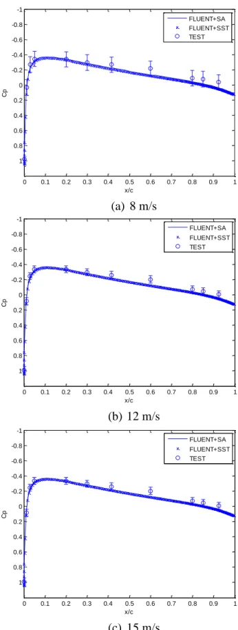
Des essais en soufflerie ont été effectués pour des ailes d'essai avec à des angles d’incidence de 0° et 3°, des vitesses de 8 à 20 m/s, donnant un nombre de Reynolds allant de 1,33 × 10⁵ à 3,33 × 10⁵,
avec une force d’actionnement de 65 à 100 mN/m. Les paramètres mesurés incluaient le moment de portance, la distribution de pression sur la surface de l’aile et le champ de vecteurs de vitesse (obtenu par la technique PIV) . En parallèle, des simulations CFD ont été réalisées avec ANSYS FLUENT utilisant les modèles de turbulence Sparlart-Allmaras (SA) et Shear Stress Transportation (SST) et un modèle d’actionneur plasma.
Les résultats montrent que les deux concepts d’actionnement plasma peuvent augmenter la portance pour les ailes avec des profils asymétrique et symétrique. Bien que plasma Gurney flap donne une meilleure augmentation de portance, son efficacité diminue à plus grande angle d’incidence alors que celle du plasma wing tip actuation reste à peu près le même. Les modèles de turbulence SST et SA donnent des prédictions similaires pour le deux concepts d’actionnement plasma, mais les prédictions du SST sont un peu plus proches des données expérimentales. Les résultats ont aussi validé les mécanismes d’augmentation de portance des deux concepts.
Les simulations CFD sur des ailes 3D montrent que le plasma Gurney flap donnent de meilleures performances sur les ailes effilées et balayées en raison de la réduction de la composante de vitesse de l'actionneur normale à l’actionneur plasma. Finalement, les simulations pour une aile et un plan horizontal de géométrie et échelle réalistes à des conditions de vols réelles indiquent que pour remplacer les surfaces de commande de vol traditionnelles, les actionneurs plasma doivent avoir une force d’actionnement effective de l’ordre de 25 à 70 N/m aux conditions de croisière haute-subsonique et d'environ 100 N/m aux conditions d'atterrissage et de décollage. Cependant, à force d’actionnement équivalente, le plasma wing tip actuation n’apporte pas de contribution signifiante à l’augmentation de la portance.
ABSTRACT
Traditional aircraft control surfaces consist of flaps, slats, ailerons, tail planes, and associated mechanical/pneumatic systems, which greatly contribute to the total weight and fuel consumption of airplanes. Various flow control devices have been proposed and studied to replace traditional flight control surfaces, such as synthetic jets and Micro Electro Mechanical Systems actuators. The recently developed dielectric barrier discharge (DBD) plasma actuator is potentially a more effective and robust alternative. The DBD plasma actuator converts electricity directly into flow momentum near the surface through partial ionization of air. The plasma actuator is simple, easy to integrate, non-intrusive (low to zero protrusion) and has a fast response time, which makes it ideal for aerodynamic applications.
The present work greatly advances the study of two novel plasma actuation concepts for lift enhancement of wings at low angle of attack for flight control without movable surfaces. The first is the plasma Gurney flap which consists of two spanwise DBD actuators placed on both sides of the wing near the trailing edge to change the flow curvature in the trailing edge region. The second is plasma wing tip actuation, in which chordwise DBD actuators are placed in the wing tip region to alter the wing tip vortex. Prior individual assessments of each concept had been carried out with preliminary CFD simulations and/or wind experiments using roughly built 2D extruded wings with an asymmetrical airfoil at very low speed and zero angle of attack. The objectives of this research are to assess these concepts for wings with both asymmetrical as well as symmetrical profiles (for use as tail planes); evaluate their effectiveness at a non-zero angle of attack and for tapered and swept wings; and predict the actuation requirements for full-scale realistic wings and tail planes under operating conditions of a typical high-subsonic commercial airliner.
The methodology consists of setting up and carrying out more detailed wind tunnel experiments on well-designed 2D extruded wings with asymmetrical and symmetrical profiles to validate numerical tools, which are then used to assess the concepts for 3D wing geometries and at real aircraft operating conditions.
Wind tunnel tests were carried out for test wings at 0° and 3° angle of attack, velocity from 8 to 20 m/s, Reynolds numbers ranging from 1.33 × 10⁵ to 3.33 × 10⁵, equipped with plasma actuators operating at actuation strength ranging from 55 to 90 mN/m. The measured parameters include lift moment, surface pressure distribution and velocity vector field (through PIV). In parallel, CFD
simulations were carried out with ANSYS FLUENT using Sparlart-Allmaras (SA) and Shear Stress Transportation (SST) turbulence models and an engineering plasma actuator model. The results also validate the mechanisms behind the increase in lift by the two plasma actuation concepts. The results showed that both plasma actuation concepts can increase lift for wings with asymmetrical and symmetrical profiles with the plasma Gurney flap providing much higher lift increase than the plasma wing tip actuation. However, the plasma Gurney flap effectiveness decreases at higher angle of attack while that of the wing tip plasma actuator remains about the same. The SST and SA turbulence models give similar predictions for the two plasma actuation concepts, with SST providing a slightly closer match with test data. CFD simulations on 3D wings show that the plasma Gurney flap has better performance on tapered and swept wings because of the reduction of velocity component normal to plasma actuator. Finally, CFD simulations for realistic wing and tail plane geometries at real fight conditions indicate that an effective plasma actuation strength required for the plasma Gurney flap to replace the flight control surfaces would be on the order of 25 – 70 N/m at high subsonic cruise conditions, and about 100 N/m at landing/takeoff conditions. For the same actuation strength, the contribution to lift increase by the plasma wing tip actuation concept is not significant.
TABLE OF CONTENTS
DEDICATION ... III ACKNOWLEDGEMENTS ... IV RÉSUMÉ ... V ABSTRACT ...VII TABLE OF CONTENTS ... IX LIST OF TABLES ... XI LIST OF FIGURES ...XII LIST OF SYMBOLS AND ABBREVIATIONS... XIX LIST OF APPENDICES ... XXICHAPTER 1 INTRODUCTION ... 1
1.1 Background ... 1
1.2 Lift Alteration Concepts at Low Angle of Attack ... 3
1.3 Objectives ... 5
1.4 Thesis Outline ... 6
CHAPTER 2 LITERATURE REVIEW ... 7
2.1 Streamline Curvature Technique ... 7
2.2 Tip Vortex Management ... 16
2.3 Plasma Actuation for In-Flight Application ... 29
2.4 Plasma Model ... 31 CHAPTER 3 METHODOLOGY ... 34 3.1 General Approach ... 34 3.2 Experimental Study ... 35 3.2.1 Wind Tunnel ... 35 3.2.2 Wings ... 37 3.2.3 Plasma Actuators ... 41 3.2.4 Endplates ... 45 3.2.5 Force Measurements ... 48 3.2.6 Pressure Measurements ... 49 3.2.7 PIV Setup ... 50 3.2.8 LabVIEW Program ... 51
3.2.9 Data Reduction ... 52
3.3 Numerical Study ... 54
3.3.1 Test Wing Simulations ... 59
3.3.2 Tapered & Swept Wing Simulations ... 63
3.3.3 Realistic Wing Simulations ... 64
CHAPTER 4 EXPERIMENTAL & CFD RESULTS ... 67
4.1 Wings without Actuation ... 67
4.2 Wings with Plasma Gurney Flap ... 73
4.2.1 Asymmetrical Wing (AG) ... 73
4.2.2 Symmetrical Wing (NG) ... 79
4.3 Wings with Plasma Wing Tip Actuation ... 83
4.3.1 Asymmetrical Wing (AT) ... 83
4.3.2 Symmetrical Wing (NT) ... 89
4.4 Discussion ... 92
CHAPTER 5 CFD STUDY ON REAL WING GEOMETRIES AND REAL FLIGHT CONDITIONS ... 95
5.1 Performance of Plasma Gurney Flap on Tapered & Swept Wings ... 95
5.2 CFD Tool Assessment at High Speed ... 97
5.3 Assessment of Plasma Actuation Concepts for Full-scale Aircraft ... 101
5.4 Discussion ... 116
CHAPTER 6 CONCLUSION AND RECOMMENDATIONS ... 118
BIBLIOGRAPHY ... 120
LIST OF TABLES
Table 3-1 Solver settings in FLUENT ... 56 Table 5-1 Comparison of CFD simulation with data from literatures ... 101
LIST OF FIGURES
Figure 1-1 Dielectric barrier discharge plasma actuator [6] ... 2
Figure 1-2 Plasma Gurney flap concept [12] ... 4
Figure 1-3 Plasma wing tip actuation concept [6] ... 5
Figure 2-1 Source of lift and lift alteration through streamline curvature change ... 7
Figure 2-2 Coanda circulation control at trailing edge (a) streamlines (b) section lift coefficients [14] ... 8
Figure 2-3 Schematic of wings with trailing edge suction [16] ... 9
Figure 2-4 A schematic of ZNMF jet [17] ... 9
Figure 2-5 Virtual aero-shaping airfoil model with a ZNMF jet [3] ... 10
Figure 2-6 UAV model upper surface geometry with sensors and synthetic jets [20] ... 11
Figure 2-7 (a) Streamlines from LDA measurement with Gurney flap (b) corresponding CL vs α measurements [23] ... 11
Figure 2-8 Gurney flap near main-element trailing edge of two-element airfoil [26] ... 13
Figure 2-9 Cl vs α of vertical trailing edge plasma Gurney flap on NACA0012 airfoil [40] ... 14
Figure 2-10 (a) NACA0012 with Gurney flap and plasma actuator; (b) corresponding Cl vs α measurements [42] ... 15
Figure 2-11 Measured velocity vectors at trailing edge of NACA4424 with plasma Gurney flap with background velocity deducted [12] ... 15
Figure 2-12 Plasma Gurney flap from Feng [43] ... 16
Figure 2-13 Perspective view of the velocity from experiment and simulation [44] ... 17
Figure 2-14 Effect of tip vortex induced downwash on angle of attack and drag [45] ... 17
Figure 2-15 General shapes of four typical wing tip extensions [46] ... 18
Figure 2-16 (a) Typical winglet configuration [47] and (b) the flow and force near the wing tip[48] ... 19
Figure 2-17 A general layout of the Whitcomb winglet [49] ... 19
Figure 2-18 A wing model (a) and the relative lift increase by wing tip blowing (b) [55] ... 21
Figure 2-19 Blowing configurations tested for a square tip (a) and a rounded tip (b) [56] ... 21
Figure 2-20 Wing with pulse jet and vortex center position with varying flow rate [57] ... 22
Figure 2-21 Wing model and the suction holes [58] ... 22
Figure 2-23 (a) Combined dual synthetic jet and (b) its effect on tip vortex footprint of a
NACA0015 wing suction side [61] ... 24
Figure 2-24 Wing geometry and plasma actuator locations [6] ... 25
Figure 2-25 Vorticity contours downstream of trailing edge without and with plasma [6] ... 26
Figure 2-26 Wing tip plasma actuator configurations and experimental results [64] ... 26
Figure 2-27 Force coefficients as a function of wing tip plasma actuator induced velocity [65] . 27 Figure 2-28 Schematic of the DBD plasma actuator arrangements (left) and the effect on trailing edge downstream tip vortex vorticity (right) [66] ... 28
Figure 2-29 Schematic of wing tip plasma actuators [67] ... 28
Figure 2-30 High speed influence on the relative plasma actuator performance and corresponding drop as a function of scaling number K [69] ... 30
Figure 2-31 Wind tunnel layout (a) and experimental setup [70] ... 31
Figure 2-32 A multi-network model for a DBD plasma actuator [73] ... 32
Figure 2-33 Time average spatial distribution of the force from plasma actuator [74] ... 33
Figure 3-1 Top and side elevation view of closed-loop wind tunnel ... 36
Figure 3-2 Wind tunnel test section ... 36
Figure 3-3 Airfoil profiles (a) Aerospatiale-A (b) NACA 0012 ... 37
Figure 3-4 Design of Aerospatiale-A extruded wing for plasma Gurney flap (AG) ... 38
Figure 3-5 Design of NACA 0012 extruded wing for plasma Gurney flap (NG) ... 38
Figure 3-6 Design of Aerospatiale-A wing for wing tip plasma actuator (AT) ... 39
Figure 3-7 Design of NACA 0012 wing for wing tip plasma actuator (NT) ... 39
Figure 3-8 Assembled Aerospatiale-A wing with plasma Gurney flap (AG) ... 40
Figure 3-9 Assembled Aerospatiale-A wing with wing tip plasma actuators (AT) ... 40
Figure 3-10 Schematic of plasma actuators ... 41
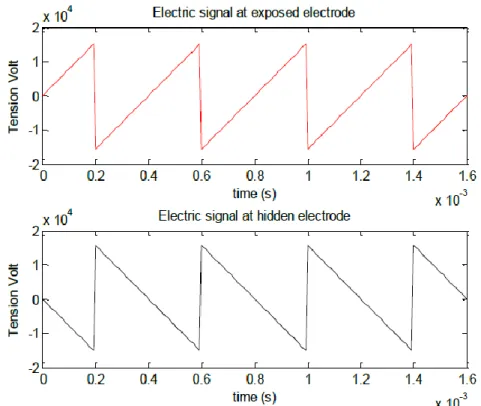
Figure 3-11 Negative saw tooth input signal for plasma actuator electrodes ... 42
Figure 3-12 Positions of plasma Gurney flap for the NG and AG wings ... 43
Figure 3-13 Geometrical layout of plasma Gurney flap on the suction side ... 43
Figure 3-14 Geometrical layout of plasma wing tip actuators (left: top view; right: cross section view from upstream) ... 44
Figure 3-15 Plasma distribution for wing tip plasma actuators ... 45
Figure 3-17 Wing models with endplates ... 46
Figure 3-18 Test model and L-shaped force balance ... 47
Figure 3-19 Angle of attack measurement for test model ... 47
Figure 3-20 Schematic and picture of L-shaped force balance ... 49
Figure 3-21 Calibration setup for L-shaped force balance ... 49
Figure 3-22 Schematic of PIV setup for plasma Gurney flap ... 51
Figure 3-23 Display Panel of LabVIEW Acquisition Program ... 52
Figure 3-24 PIV averaged vector map from Dynamic Studio ... 54
Figure 3-25 Computed streamlines from MATLAB ... 54
Figure 3-26 Instantaneous vorticity fields for plasma actuator in quiescent air from (a) measured PIV and (b) CFD [77] ... 56
Figure 3-27 Body force implementation for the AG wing ... 57
Figure 3-28 Body force implementation for AT wing ... 58
Figure 3-29 Plasma body force distribution of AG wing ... 58
Figure 3-30 Plasma body force distribution of AT wing ... 58
Figure 3-31 Schematic of fluid domain ... 59
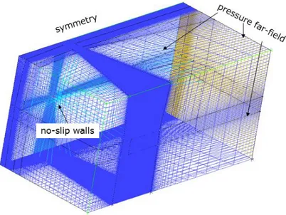
Figure 3-32 Flow domain and boundary conditions for wind tunnel simulations ... 59
Figure 3-33 Mesh topology for wings in wind tunnel ... 60
Figure 3-34 Mesh topology and surface mesh of AG wing ... 60
Figure 3-35 Mesh topology and surface mesh of AT wing ... 61
Figure 3-36 Cross section mesh (spanwise plane) for AG wing and surface mesh for AT wing . 61 Figure 3-37 Lift coefficients of experiments and simulations for NACA0012 with wing tip ... 62
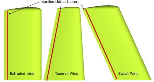
Figure 3-38 Extruded, tapered and swept wings with plasma Gurney flap ... 63
Figure 3-39 M6w and M6t wings with two plasma actuation concepts ... 65
Figure 3-40 Fluid domain and boundary conditions for realistic wing simulations ... 66
Figure 3-41 Surface mesh for the realistic wing simulations ... 66
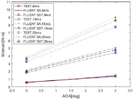
Figure 4-1 Moments comparison of TEST versus CFD for AG wing (AOA = 0°) ... 67
Figure 4-2 Moments comparison of TEST versus CFD for AT wing (AOA = 0°) ... 68
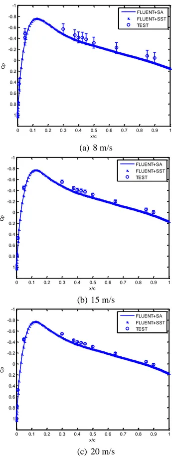
Figure 4-3 Pressure distribution of experiments and simulations for AT wing (AOA = 0°) ... 69
Figure 4-4 Pressure distribution of experiments and simulations for wing NT (AOA = 0°) ... 70
Figure 4-6 Effect of AOA on lift moments of TEST and CFD for AT wing ... 71
Figure 4-7 Pressure distribution of experiments and simulations for AT wing (AOA = 3°) ... 72
Figure 4-8 Effect of plasma Gurney flap on AG wing at AOA = 0°, FB =55 mN/m ... 73
Figure 4-9 Predicted mid-span pressure distribution of AG wing (8 m/s, AOA = 0°) ... 74
Figure 4-10 Predicted mid-span pressure distribution of AG wing (15 m/s, AOA = 0°) ... 74
Figure 4-11 Predicted mid-span pressure distribution of AG wing (20 m/s, AOA = 0°) ... 75
Figure 4-12 Streamlines near trailing edge of AG wing from CFD and PIV (8 m/s, AOA = 0°) 76 Figure 4-13 Streamlines near trailing edge of AG wing from CFD and PIV (15 m/s, AOA = 0°) ... 77
Figure 4-14 Streamlines near trailing edge of AG wing from CFD and PIV (20 m/s, AOA = 0°) ... 77
Figure 4-15 Effect of AOA on plasma Gurney flap for AG wing at 8 m/s, FB = 55 mN/m ... 78
Figure 4-16 Streamlines near trailing edge of AG wing at 20 m/s, AOA = 0° and 3° ... 78
Figure 4-17 Streamlines near trailing edge of AG wing at 20 m/s without plasma, AOA = 0° & 3° ... 79
Figure 4-18 Effect of plasma Gurney flap on NG wing at AOA = 0°, FB = 60 mN/m ... 80
Figure 4-19 Mid-span pressure distributions for NG wing (AOA = 0°, FB = 60 mN/m) ... 81
Figure 4-20 Streamlines near trailing edge of NG wing from CFD and PIV (8 m/s, AOA = 0°) 82 Figure 4-21 Streamlines near trailing edge of NG wing from CFD and PIV (12 m/s, AOA = 0°) ... 82
Figure 4-22 Streamlines near trailing edge of NG wing (15 m/s, AOA = 0°) ... 83
Figure 4-23 Effect of wing tip actuation on lift moment for wing AT (AOA = 0°, FB =65 mN/m) ... 84
Figure 4-24 Effect of wing tip actuation on lift moment for AT wing (AOA = 0°, FB =90 mN/m) ... 84
Figure 4-25 Predicted (CFD) spanwise lift change by plasma for AT wing (AOA = 0°, FB = 65 mN/m) ... 85
Figure 4-26 Predicted (CFD) contours of wake vorticity one chord downstream for AT wing (AOA = 0°) without (left) and with plasma actuation (right, FB =65 mN/m) ... 86
Figure 4-27 Predicted (CFD) local AOA at 0.1chord upstream leading edge of AT wing with and without plasma (AOA = 0°, FB =65 mN/m) ... 87
Figure 4-28 Effect of AOA on wing tip actuation effectiveness for AT wing (FB = 65 mN/m) .. 88
Figure 4-29 Predicted (CFD) local AOA at 0.1chord upstream leading edge of AT wing with and without plasma (AOA = 3°, FB =65 mN/m) ... 88
Figure 4-30 Effect of wing tip actuation on lift moment for NT wing (AOA = 0°, FB =80 mN/m)
... 89 Figure 4-31 Spanwise lift for symmetrical wing with wing tip actuation (AOA = 0°, FB = 80 mN/m)
... 90 Figure 4-32 Predicted (CFD) contours of wake vorticity one chord downstream for NT wing (AOA
= 0°) without and with plasma actuation (right, FB =80 mN/m) ... 91
Figure 4-33 Predicted (CFD) local AOA at 0.1chord upstream leading edge of NT wing without and with plasma (AOA = 0°, FB =80 mN/m) ... 92
Figure 4-34 Comparison of lift increase by plasma Gurney flap with existing data ... 94 Figure 4-35 Comparison of moment increase by wing tip plasma actuators with existing data ... 94 Figure 5-1 Effect of 3D wing geometry on plasma Gurney flap effectiveness (20 m/s, AOA = 0°,
FB= 100 mN/m) ... 95
Figure 5-2 Velocity triangles at trailing edges of extruded, tapered and swept wings ... 96 Figure 5-3 Effect of velocity on lift for AT wing with and without plasma Gurney flap ... 96 Figure 5-4 Predicted streamlines near trailing edges (CFD) of AT, ATtap and ATsw wings at mid-span (20 m/s, AOA = 0°, FB= 100 mN/m) ... 97
Figure 5-5 Pressure contour by FLUENT (left) compared with WIND results [84] (right) for M6 wing (Mach = 0.84, AOA = 3.06°, Re = 1.172 × 10⁷) ... 98
Figure 5-6 Pressure distributions of FLUENT, WIND, and experiment at 20% span for wing M6 (Mach = 0.84, AOA = 3.06°, Re = 1.172 × 10⁷) ... 99
Figure 5-7 Pressure distributions of FLUENT, WIND, and experiment at 65% span for wing M6 (Mach = 0.84, AOA = 3.06°, Re = 1.172 × 10⁷) ... 99 Figure 5-8 Pressure distributions of FLUENT, WIND, and experiment at 80% span for wing M6
(Mach = 0.84, AOA = 3.06°, Re = 1.172 × 10⁷) ... 100 Figure 5-9 Pressure distributions of FLUENT, WIND, and experiment at 99% span for wing M6
(Mach = 0.84, AOA = 3.06°, Re = 1.172 × 10⁷) ... 100 Figure 5-10 Moment and lift for M6t and M6w wings ... 102
Figure 5-11 Moment coefficient increase for M6w wing with plasma Gurney flap (AOA = 3°, Mach = 0.84, Re = 4.94 × 10⁷) ... 102
Figure 5-12 Pressure contours for M6w wing suction side without (left) and with (right) plasma Gurney flap (AOA = 3°, Mach = 0.84, Re = 4.94 × 10⁷, FB= 20 N/m) ... 103
Figure 5-13 Mach number contours for M6w wing mid-span without (left) and with (right) plasma Gurney flap (AOA = 3°, Mach = 0.84, Re = 4.94 × 10⁷, FB= 20 N/m) ... 103
Figure 5-14 Pressure distributions for M6w wing with and without plasma Gurney flap at different spanwise positions (AOA = 3°, Mach = 0.84, Re = 4.94 × 10⁷, FB= 20 N/m) ... 104
Figure 5-15 Middle-span streamlines for M6w wing with and without plasma Gurney flap (AOA = 3°, Mach = 0.84, Re = 4.94 × 10⁷, FB=5 and 20 N/m) ... 105
Figure 5-16 Lift coefficient increase for M6t wing with plasma Gurney flap (AOA = 0°, Mach = 0.84, Re = 1.54 × 10⁷) ... 106 Figure 5-17 Pressure distributions for M6t wing with and without plasma Gurney flap at different
spanwise positions (AOA = 0°, Mach = 0.84, Re = 1.54 × 10⁷, FB =20 N/m) ... 107
Figure 5-18 Mid-span streamlines for M6t wing with and without plasma Gurney flap (AOA=0°, Mach = 0.84, Re = 1.54 × 10⁷, FB=5 and 20 N/m)... 107
Figure 5-19 One chord downstream of trailing edge vorticity contours for M6w wing with and without plasma wing tip actuation (AOA=3°, Mach = 0.84, Re = 4.94 × 10⁷, F
B=20 and 40
N/m) ... 109 Figure 5-20 One chord downstream of trailing edge vorticity contours for M6t wing with and
without plasma wing tip actuation (AOA=0°, Mach = 0.84, Re = 1.54 × 10⁷, F
B=20 and 40
N/m) ... 110 Figure 5-21 Local AOA at 0.1 chord upstream leading edge of M6w wing with and without plasma
wing tip actuation (AOA = 3°, Mach = 0.84, Re = 4.94 × 10⁷) ... 111 Figure 5-22 Local AOA at 0.1 chord upstream leading edge of M6t wing with and without plasma
wing tip actuation (AOA = 0°, Mach = 0.84, Re = 1.54 × 10⁷) ... 111 Figure 5-23 Moment coefficient increase for M6w wing with plasma Gurney flap (AOA = 3°,
Mach = 0.3, Re = 6.21 × 10⁷) ... 112 Figure 5-24 Lift coefficient increase for M6t wing with plasma Gurney flap (AOA = 0°, Mach =
Figure 5-25 Pressure distributions for M6w wing with and without plasma Gurney flap at different spanwise positions (AOA = 3°, Mach = 0.3, Re = 6.21 × 10⁷, F
B=20 N/m) ... 113
Figure 5-26 Mid-span streamlines for M6w wing with and without plasma Gurney flap (AOA = 3°, Mach = 0.3, Re = 6.21 × 10⁷, FB=20 N/m) ... 114
Figure 5-27 Pressure distributions for M6t wing with and without plasma Gurney flap at different spanwise positions (AOA = 0°, Mach = 0.3, Re = 1.93 × 10⁷, FB=20 N/m) ... 115
Figure 5-28 One chord downstream of trailing edge vorticity contours for M6w wing with and without plasma wing tip actuation (AOA = 3°, Mach = 0.3, Re = 6.21 × 10⁷) ... 116 Figure 5-29 One chord downstream of trailing edge vorticity contours for M6t wing with and
LIST OF SYMBOLS AND ABBREVIATIONS
Symbols
a force balance ratio
AR aspect ratio
Cμ blowing momentum coefficient
CL lift coefficient
CM moment coefficient
Cp pressure coefficient
c wing chord
d dielectric thickness
E electric field strength
FB plasma actuation strength
f frequency
RH relative humidity
L1 distance from wing root to balance pivot
L2 distance from scale to balance pivot
M molar mass
𝑚̇ jet mass flow rate
p pressure
qc charge density
q free stream dynamic pressure
R universal gas constant
R̅ balance average reading
Re Reynold number
S area
T temperature
U velocity
V applied voltage
x wing chordwise location
𝜌 density
𝑣𝑑 drift velocity of the momentum imparting ions
Subscript atm atmosphere d dry air j jet N normal component s static sw swept wing t total
tap taper wing
v vapor
∞ free stream
Abbreviations
AOA angle of attack
AG extruded Aerospatiale-A wing with plasma Gurney flap AT extruded Aerospatiale-A wing with wing tip plasma actuator CFD Computational Fluid Dynamics
NG extruded NACA0012 wing with plasma Gurney flap NT extruded NACA0012 wing with wing tip plasma actuator
SA Spalart-Allmaras
LIST OF APPENDICES
APPENDIX A – WIND TUNNEL CHARACTERISATION ... 128
APPENDIX B – WIND TUNNEL TEST ... 136
APPENDIX C – PLASMA CHRACTERLISATION ... 140
APPENDIX D – MESH STUDY ... 145
APPENDIX E – CFD RESULTS WITH TRANSITION SST MODEL ... 148
APPENDIX F – PLASMA IMPLEMENTATION ... 152
CHAPTER 1
INTRODUCTION
1.1 Background
The world commercial aircraft market has grown rapidly in recent decades, as a result of expanding trade and travel between different countries and regions. At the same time, as climate change and impending energy shortage become more serious, there is a great demand for a reduction in pollution and fuel consumption associated with aircraft operation, for which weight reduction is a key contributor. The replacement of the traditional lift augmentation and flight control surfaces, namely flaps, slats, ailerons, elevator and rudder, and associated mechanical/pneumatic systems would greatly contribute to weight savings and/or provide additional volume for fuel storage contributing to flight range extension as well as reduction production and operating costs of the aircraft.
Flow control technology using pneumatic actuators to blow the boundary layers over the wing (Coanda effect) [1] or boundary layer suction [2] for lift increase and drag reduction have been tested for several decades. However, the weight and complexity/cost associated with integrating the associated systems (pressurised air/vacuum source, valves and piping) have prevented any significant implementation of these systems in commercial aviation. The integration issues may be resolved with recent electrically driven micro-actuation technology such as synthetic jets [3] which add momentum in the boundary layer with zero net mass addition and MEMS (Micro Electro-Mechanical Systems) actuators such as micro-balloons [4] and micro-flaps [5] for altering surface roughness. However, the robustness of these actuators in a harsh aircraft operating environment and resulting maintenance issues reduce the particular application of this technology.
The aerodynamic plasma actuator is a recent technology which came shortly after the advent of MEMS actuators and is very promising for practical application of flow control technology in aircraft applications. It is a simple solid-state device that allows conversion of electrical energy directly into flow acceleration through partial air ionization. The most common form of this actuator is the DBD (dielectric barrier discharge) actuator. As illustrated in Figure 1-1 [6], a DBD actuator essentially consists of two axially offset electrodes separated by one or multiple layers of dielectric materials. When an AC voltage of several kilovolts and several kilohertz is applied at the electrodes, ionized particles are formed in the air which are then accelerated by the electric field
between the two electrodes. These ions collide with neutral air particles imparting momentum resulting in flow acceleration in the thin layer (on the order of a millimetre thick) of air next to the surface. More details on the physics of DBD plasma actuators can be found in reference [7]. The simplicity and solid-state nature of DBD actuators make them potentially robust with high bandwidth while their thinness and purely electrical nature could make their integration and maintenance potentially much simpler than other actuators. Finally, since the exposed electrode is very thin and can be made flush with the aerodynamic surface, the actuator would not interfere with the flow when not in use.
Figure 1-1 Dielectric barrier discharge plasma actuator [6]
The first proposed application for DBD plasma was in fact to suppress boundary layer separation on wing profiles at high angle of attack (AOA) by placing DBD actuators at the leading edge, injecting momentum downstream [8]. This application would allow for the elimination of slats and flaps by allowing the aircraft to take off and land at higher angle of attack. Later suggested applications of DBD plasma actuators consist of controlling boundary layer separations on low pressure turbine’s blades [9], delaying boundary layer transition [10] for drag reduction and delaying rotating stall in axial compressors [11]. However, achieving moderate lift change on wings and tail planes with plasma actuators for flight control without movable surfaces (ailerons, rudder and elevators), which is the subject of this research, is more difficult and has been less investigated.
1.2 Lift Alteration Concepts at Low Angle of Attack
Flow control applications aim at placing actuators in strategic environment to have macroscopic effect with limited actuator input power. In this respect, most flow control applications in aeronautics have placed the actuators near boundary layer separation points where small perturbations can have a large impact. This has been particularly true for plasma actuators, for which current achievable strength is still relatively weak, for stall delay in wings at high angle of attack, where the boundary layer on the suction side is close to separation. However, flight control at low angle of attack with plasma actuators present a particular challenge in that the boundary layer is well attached to the wing/empennage surface and thus much less sensitive to the relatively weak flow perturbations from these actuators. For this reason, the first attempt involved implementing a ramp on the wing surface for inducing boundary layer separation which can then be suppressed with a plasma actuator to alter lift. However, this solution is far from desirable as it imposes a nominal drag penalty on the aircraft. Two flow control concepts for altering lift at low angle of attack without nominal performance penalty were later developed and investigated at École Polytechnique de Montréal, and are described below.
The first concept studied by Ueno [12] relies on modifying streamline curvature at the airfoil trailing edge to increase lift. As illustrated in Figure 1-2, this concept consists of placing two spanwise plasma actuators near the trailing edge of an airfoil, one on the suction side adding momentum downstream and the other on the pressure side injecting momentum upstream. This combination effectively curves the flow at the trailing edge in the same manner as a permanently installed Gurney flap for enhancement of lift, but which can be turned on and off as needed. This concept was hence referred to as the plasma Gurney flap. Ueno installed the plasma Gurney flap on a ten-inch chord 2-D extruded wing with a NACA 4424 profile and tested it in a low speed wind tunnel with an incoming flow velocity range of 6 - 16 m/s for a Reynolds number ranging from 1.2 × 10⁵ to 3.0 × 10⁵. While the actuator strength was not explicitly given, it can be estimated to be around 20 mN/m based on the nature of the dielectric used in the actuator and the actuator input signal suggested. Force measurements and PIV flow visualization were conducted. His results showed that the plasma Gurney flap leads to an increase of 0.02 to 0.18 in lift coefficient and that the final effect is approximately the sum of the effect of each of the two actuators.
The second concept is plasma wing tip actuation, studied by Boesch et al. [6]. It consists of placing plasma actuators around the wing tip, as illustrated in Figure 1-3, adding momentum in the
direction opposite that of the tip vortex to diffuse the latter. The tip vortex induces downwash near the wing tip resulting in lift decrease and drag increase for the wing. The reduction of these effects through a more diffused tip vortex increases lift. Conversely, the concept can be applied to a symmetrical airfoil at zero angle of attack (zero nominal lift) such as in the case of aircraft tail planes to induce a tip vortex and generate different lift for yaw and pitch control. CFD simulations were carried out by Boesch et al. [6] for a finite six-inch chord 2D wing with a NACA 4418 profile and a rounded wing tip at zero angle of attack in a wind tunnel setting with an incoming velocity of 15 m/s for a Reynolds number of 1.5 × 10⁵. The simulation results showed that the actuators lead to a significant diffusion of the tip vortex downstream of the trailing edge, resulting in a lift increase of up to 20% with maximum 400 mN/m. Preliminary corresponding wind tunnel experiments with suction and pressure side actuators of limited actuation strength (40 mN/m) showed that for lift change versus incoming velocity the experimental results matched the predicted simulations in trend.
Figure 1-3 Plasma wing tip actuation concept [6]
1.3 Objectives
The previous works on the plasma Gurney flap and plasma wing tip actuation concepts for lift increase at low angle of attack produced promising results [6] [12]. However, these studies were preliminary as the test velocity and Reynolds number were far below realistic aircraft operating conditions. The wing geometries considered were also ideal compared to actual aircraft wings and tail planes operating at non-zero angles of attack. As such, the following research questions need to be addressed for these two concepts to move to the next technology readiness level and eventually into industrial research and development:
- Will these concepts work for zero nominal lift (symmetric) airfoils? - How does the effectiveness of these concepts change with angle of attack?
- How effective are the plasma Gurney flap and plasma wing tip actuation concepts for more realistic wing geometries (3D tapered swept wings)
- How effective are these concepts for real wing geometries under realistic flight conditions? - What are the actuation requirements at realistic operating conditions?
- Can these concepts be combined to augment the lift alteration?
To answer these questions, a computational approach combined with wind tunnel experiments is used in this project, to evaluate and assess the effect of these two concepts. Thus, the specific objectives of this project are to:
1) Evaluate the plasma Gurney flap and plasma wing tip actuation concepts for wings with asymmetric and symmetric profiles
2) Assess the effectiveness of these plasma concepts at different angles of attack 3) Assess the effectiveness of these plasma concepts on tapered and swept wings
4) Evaluate the actuation requirements of the two concepts for realistic wings and tail planes of a typical full-scale high subsonic commercial airliner
1.4 Thesis Outline
This thesis is organized as follows: following this introduction, Chapter 2 presents a detailed literature review on lift alteration techniques at low angle of attack, as well as plasma actuation and in-flight application and plasma model. In Chapter 3, the methodology used to attain the above objectives is presented. This is followed by the experimental and CFD results in Chapter 4. In Chapter 5, the validated CFD tools are used to study plasma actuators on realistic wing geometries and realistic in-flight conditions. Finally, Chapter 6 summarizes the conclusions and provides recommendation for future work.
CHAPTER 2
LITERATURE REVIEW
This chapter first provides a brief review of the flow control techniques for lift alteration on wings at low angle of attack. These flow control techniques can be divided into two main categories: streamline curvature control and wing tip vortex management. Then, the plasma actuation for in-flight application and plasma model will be addressed in the end of this chapter.
2.1 Streamline Curvature Technique
Streamline curvature techniques rely on changing the streamline curvature to alter the pressure distribution over the wing. As illustrated in Figure 2-1, lift comes from the larger curvature of streamlines over the top surface of the wing due to air following the latter’s shape. A pressure gradient is set up within the flow field to provide the required centripetal force for the fluid particles to turn and follow the required flow path. Since the pressure increases in the direction of curvature and given the fact that the pressure far away from the wing is uniform, the pressure at the upper wing surface with larger streamline curvature must be less than that at the lower wing surface, resulting in lift. Any device that can change the curvature of the flow will alter the lift. This is the principle behind movable flight control surfaces such as ailerons, elevators and rudders.
Figure 2-1 Source of lift and lift alteration through streamline curvature change
p p p p = p p < p p p U∞
Several concepts have been developed over the past decades to control lift at low angle of attack through streamline curvature without resorting to movable flight control surfaces. The first is the Coanda jet which is an application of the Coanda effect. The Coanda effect is the tendency of a fluid jet to be attached to a surface, which one can observe from a spinning ping pong ball held in a diagonal stream of air [13]. When applied to airfoils at low angle of attack, a high-speed jet is blown over the suction side near the trailing edge and the jet follows the curved trailing edge surface, as illustrated in Figure 2-2(a). Therefore, the streamlines moving over the wing are bent downwards at the trailing edge, resulting in an increase of lift. Novak et al. [14] tested this effect on a 15-inch chord airfoil at zero angle in a flow of 42.50 m/s for a Reynolds number of 1,000,000. They achieved an increase in sectional lift coefficient Cl from 0.5 to 6.8 with a blowing momentum
coefficient Cμ from 0 to 0.36 as shown in Figure 2-2(b) (Cμ=mjUj/qS, where mj is the jet mass flow
rate, Uj is the jet exit velocity, q is free stream dynamic pressure, and S is the model area).However,
this technique can introduce noise from the jet and the jet can easily detach from the curved surface, which limits the effectiveness of the concept. Furthermore, the required high-pressure source and pressure cavity built within the wing structure would introduce integration complexity and additional costs.
(a) (b)
Figure 2-2 Coanda circulation control at trailing edge (a) streamlines (b) section lift coefficients [14]
Another concept is to modify the apparent local surface curvature and therefore to redirect the external flow. This concept was first developed by Raspet[15] and Hazen et al.[16]. Raspet added a suction source with a flow coefficient of 0.0023 on a trailing edge slot covering 65% of the span
of a sailplane. No improvement in the lift/drag ratio was found. By applying trailing edge suction asymmetrically, a rolling behavior was measured which was insufficient for effective lateral control. Hazen et al. tested trailing edge suction (shown in Figure 2-3) on a modified eight-inch chord NACA 23015 airfoil and found that lift increased to a limiting values with increasing suction quantity at trailing edge.
Figure 2-3 Schematic of wings with trailing edge suction [16]
Another technique for generating trapped vortex is the zero-net-mass-flux (ZNMF) or synthetic jet. The ZNMF jet consists of a cavity with an oscillating membrane at one end and an orifice at the other end, as illustrated in Figure 2-4 [17]. In suction mode, the cavity sucks fluid from all direction followed by a blowing mode in which this fluid leaves only in one direction. The result is a directional momentum addition without net mass addition. Chatlynne et al. [18] and Amitay et
al.[19] applied the ZNMF jet to virtually shape the surface of an airfoil and then to reduce pressure
drags at low angle of attack with minimum penalty in lift, as shown in Figure 2-5.
Figure 2-5 Virtual aero-shaping airfoil model with a ZNMF jet [3]
The concept of virtual aero-shaping by ZNMF jets was later applied to a three dimensional wing. Farnsworth et al. [20] applied the synthetic jets on a scaled Stingray unmanned aerial vehicle (UAV) in a flow of 30.5 m/s and 25 m/s with a mean aerodynamic chord-based Reynolds number of 185,000. Figure 2-6 illustrates the upper surface geometry of the UAV model with sensors and synthetic jets. The model incorporated twelve pairs of synthetic jets that are issued through rectangular orifices, and the synthetic jets were formed by the periodic motion of a piezoelectric disk mounted on the bottom wall of a sealed cavity. The results showed that the synthetic jets were able to alter the local streamlines on the suction side of wing surfaces and to displace the boundary layer by forming a small quasi-steady interaction region. They obtained a maximum CL increase of
0.11 with 6 jets turned on at AOA= 2°. However, since the synthetic jet actuators are often very small to achieve high bandwidth as well as ease of integration, they could be subject to clogging in a real aircraft operating environment.
A third strategy for altering lift at low angle of attack is the Gurney Flap. It is a very simple but effective device, which consists of a small flap located at the trailing edge perpendicular to the chord line or pressure surface of an airfoil. Invented by Dan Gurney in early 1970s, this device has been subsequently studied by numerous researchers. Liebeck [21] applied a Gurney flap to a Newman symmetric airfoil and indicated that there was a turning of the flow over the back of the flap and a reverse flow directly behind it. These observations were corroborated in water tunnel experiments at lower Reynolds number by Neuhart and Pendergraft [22].
This flow structure is more precisely shown by Jeffrey et al. [23] who carried out laser Doppler anemometry (LDA), surface pressure and force measurements as well as smoke visualization for a single-element wing (Eppler e423 profile) with a Gurney flap, at free stream velocity up to 40 m/s
and at a Reynolds number up to 8.9 105. Their results indicated a twin vortex structure downstream of the Gurney flap (see Figure 2-7(a)), with a convex streamline curvature over the trailing edge reducing local pressure on the suction side. In parallel, the flow slowed down with a similar curvature ahead of the Gurney flap near the trailing edge, creating a local pressure rise on the pressure side. The combination of both effects increased the lift and pitching moment. The lift increase was almost proportional to the height of flaps, with maximum lift increase of 71% at AOA=0° and maximum lift increase of 94% at AOA=3°, as shown in Figure 2-7(b).
Figure 2-6 UAV model upper surface geometry with sensors and synthetic jets [20]
Figure 2-7 (a) Streamlines from LDA measurement with Gurney flap (b) corresponding CL vs α
Other researchers have also studied the effect of lift and drag of the basic Gurney flap with varying heights, at different angles of attack and at higher Reynolds numbers. Storms et al. [24] measured surface pressure distributions and wake profiles on a NACA 4412 with a Gurney flap to obtain lift, drag and pitching moment coefficient. The Gurney flap increased the maximum lift coefficient from 1.49 up to 1.96 (by 32%) and increased the drag at low-to-moderate lift coefficients. Jang et
al. [25] carried out a numerical study on a similar configuration with an incoming flow Mach
number of 0.085 at angles of attack from 0 to 18° and Reynolds number of 1.64 106. A maximum lift coefficient increase of 150% was obtained at zero angle of attack with a flap of 3% chord height, but with penalties in drag and moment coefficients. The authors suggested that the height of Gurney flap should be less than 1.25% chord in order to get an increase in lift with little drag increase.
Ross et al. [26] studied Gurney flaps with height from 0.125% to 1.25% chord on a two dimensional two-element airfoil NACA 632-215 Mod B with a single slotted, 30%-chord regular flap, as shown in Figure 2-8. The Reynolds number was 3.7 106, with a free stream velocity of 69 m/s. Results
showed that the maximum lift coefficient could be increased by 12% and maximum lift-to-drag by 40% with a 0.5%-chord flap at 0.5% chord upstream of the trailing edge of main element. Later, Myose et al. [27] carried out a detailed study on 2D airfoils, 3D wings, and a reflection plane model. The Reynolds number ranged from 9105 to 2.2106, with an incoming Mach number from 0.12 to 0.19 and an angle of attack ranging from -2 to 20°. For a single-element NACA 0011 airfoil, a Gurney flap of 4%-chord height leaded to an increased zero-angle lift coefficient of 0.8 at Re=2.2106 and Mach=0.13. Results showed that for all of the studied airfoils, Gurney flap can improve the maximum lift coefficient albeit with drag penalties, which is the main disadvantage of the Gurney flap.
Several improvements to the Gurney flap have been proposed. They included serrated [28], segmented [29] and perforated Gurney [30, 31] to mitigate the drag penalty. Some of them can enhance lift (segmented Gurney flap) but some may affect the lift increase as well (perforated Gurney flap). Oscillating Gurney flaps were studied by Tang and Dowekll [32] and Gerontakos and Lee [33] to enhance the maximum lift and pitching-moment coefficients under a wide range of angle of attack. However, the oscillation of flaps required more complex structure, which would be less desirable.
Last but not least, the Gurney flap have also been shown to be effective in other applications, such as rotorcraft blades [34, 35], wind turbines [36, 37] and turbine blades [38, 39].
Figure 2-8 Gurney flap near main-element trailing edge of two-element airfoil [26] With the advent of plasma actuators, several active control concepts have been proposed for lift alteration at low angles of attack. Zhang et al. [40] placed plasma actuators on the vertical trailing edge surface of a truncated NACA0012 airfoil in an attempt to replicate the effect of a Gurney flap, as shown in Figure 2-9. Simulations were carried out in ANSYS FLUENT with a phenomenological plasma model from Shyy et al. [41] at a free stream velocity of 10 m/s and Reynolds number of 6.84 105. The simulation was carried out under two-dimensional steady mode, using SA model. The non-dimensional plasma actuator strength Dc is defined as
𝐷𝑐 = 𝑞𝜌𝑈𝑐𝐸0𝐿
∞2 (2.1)
where qc is the charge density, E0 is the electric field strength, L is the height of electrode, 𝜌 is
density and 𝑈∞ is the free stream velocity. In this case, a plasma strength of 9.14 was applied in the simulation. The simulation results showed that the induced jet from plasma actuators resulted in a zero-angle lift coefficient of 0.18. However, the simulated velocity is low and there was no experimental validation of the concept.
Figure 2-9 Cl vs α of vertical trailing edge plasma Gurney flap on NACA0012 airfoil [40]
Feng et al. [42] carried out an experimental study with plasma actuator attached to a physical Gurney flap on NACA 0012, using the flap as the dielectric material, as shown in Figure 2-10(a). The maximum tested velocity and Reynolds number were limited to 5.3 m/s, and 3.5 104, respectively. They found that the lift coefficient Cl increased by 0.15 (about 22%) at Re=2.0 × 10⁴
for AOA=0 – 16°, when the actuators was attached to a 7% chord physical Gurney flap (see Figure 2-10(b)).
Ueno [12] developed and tested a new plasma Gurney flap configuration, which avoids the need to truncate the trailing edge as done by Zhang et al. [40] which is not aerodynamically desirable as well as limits the width of the DBD actuator that one can fit. As mentioned in Chapter 1, Ueno’s configuration consists of two spanwise plasma actuators placed near the trailing edge, one on the suction side inducing the ionic wind downstream and the other on the pressure side inducing upstream ionic wind. Net velocity (velocity minus background velocity) from PIV measurements by Ueno [12] shown in Figure 2-11, indicate that the net effect of trailing edge flow (acceleration of flow over the suction side and deceleration of flow at the pressure side) with this configuration is similar to that of a physical Gurney flap. At tested free stream velocities ranging from 6 m/s to 16 m/s and Reynolds number of 1.2 to 3.0 × 10⁵, this plasma Gurney flap increased the lift
coefficient by 0.18 to 0.02 (about 69% to 7%, respectively). Additional tests with each actuator turned on individually indicated that the total effect on lift is the combined effect of each actuator.
(a) (b)
Figure 2-10 (a) NACA0012 with Gurney flap and plasma actuator; (b) corresponding Cl vs α
measurements [42]
Figure 2-11 Measured velocity vectors at trailing edge of NACA4424 with plasma Gurney flap with background velocity deducted [12]
Recently, Feng [43] proposed a new plasma Gurney flap which consists of two dielectric barrier discharge plasma actuators attached to the airfoil NACA 0012 pressure surface near the trailing edge, as shown in Figure 2-12. 2D numerical study was carried out for NACA 0012 with a chord length of 1 m at background flow speed of 10 m/s and Reynolds number of 6.8 × 10⁵. And it was found that the most significant control effect occurs with only downstream plasma actuators on. The plasma Gurney flap can increase the lift coefficient before the stall, reduce the drag coefficient, and increase the lift-to-drag ratio at small angles of attack. For NACA 0012 airfoil with plasma control, the maximum lift coefficient and the maximum lift-to-drag ratio are increased by about
7.5% and 7.7%, respectively. The plasma Gurney flap have been also simulated on the pressure side of a 3D Unmanned Aerial Vehicle [43], near the trailing edge and along the whole span. The lift coefficient is increased by about 0.09 to 0.12 for the angles of attack from -2 to 16°.
Figure 2-12 Plasma Gurney flap from Feng [43]
In summary, although the streamlines curvature methods for lift increase at low angle of attack show promising results, the mechanical and pneumatic methods all come with some drawbacks that prevent them from being used for practical flight control. Furthermore, apart from the physical Gurney flap[26], none of the proposed concepts have yet been assessed at realistic flight conditions for which the Reynolds number would be on the order of 106.
2.2 Tip Vortex Management
The wing tip vortex, also known as trailing edge vortex, is the rotating flow pattern behind a finite wing when generating lift. It comes about as the high pressure air on the pressure side tends toward the lower pressure air on the suction side around the wing tip. Figure 2-13 from Dacles-Mariani et
al. [44] show the formation and convection of the wing tip vortex through measured and simulated
velocity profiles at different axial planes. This vortex induces a downwash that is largest near the wing tip, as shown in Figure 1-3, causing the incoming flow to bend downward, thus reducing the local angle of attack and resulting not only in a lift decrease near the wing tip but also an additional drag, called induced drag, as illustrated in Figure 2-14. These negative effects can be alleviated if the normally concentrated wing tip vortex can be diffused and/or moved further out from the wing tip to reduce the downwash over the outer wing span. A variety of strategies have been developed and studied to achieve these tasks.
Figure 2-13 Perspective view of the velocity from experiment and simulation [44]
Figure 2-14 Effect of tip vortex induced downwash on angle of attack and drag [45] One typical strategy is to use wing tip extension to reduce the negative effect of wing tip vortex, mainly by pushing the vortex farther outboard from the wing root, resulting in a reduction of both downwash and lift-induced drag. Various wing tip extensions have been developed [46], including rounded wing tip, spherical wing tip, squared wing tip, booster wing tip, Hoerner wing tip, raked wing tip, endplate, polyhedral wing tip and winglet. Figure 2-15 shows the shapes of four typical wing tip extensions.
Figure 2-15 General shapes of four typical wing tip extensions [46]
A winglet is a near-vertical extension of the wing tip, which can perform better in term of diffusing the vortex than previous wing tip extensions. A typical winglet is shown in Figure 2-16(a) [47]. A vortex is developed and change the relative wind direction near wing tip, as shown in Figure 2-16(b). If the winglet is fitted to the wing tip with appropriate height and orientation, the lift generated by winglets have a component pointing forward, which can reduce the drag [48].
Whitcomb [49] studied a shifted downstream winglet mounted on the tip of a narrow-body jet transport wing, with a free stream Mach number of 0.78, and Reynolds number 17.2 × 10⁶. The
winglet consisted of two spilt winglet located at wing tip with different flap angles. The primary winglet was located rearward above the tips while the smaller secondary one was placed forward below the tips, as shown in Figure 2-17. This winglet configuration reduced the induced drag by about 20%, and increased lift-drag ratio by 9%. The lift-drag ratio was more than twice as that achieved by wing tip extension configuration. Another study by Sohn et al. [50] on similar configuration also showed similar results, where the Whitcomb winglet increased the lift coefficient by 9% more than a simple fairing wing tip extension with a free stream velocity of 26 m/s and Reynolds number of 4.12 105.
(a) (b)
Figure 2-16 (a) Typical winglet configuration [47] and (b) the flow and force near the wing tip[48]
Figure 2-17 A general layout of the Whitcomb winglet [49]
While the passive techniques discussed previously may be effective, they may induce additional drag under off-design conditions unless the devices involved can be retracted, which would incur the same mechanical inconveniences as using movable flight control surfaces. As such, active control techniques that can be easily turned on and off would be more practical. The first technique developed for wing tip vortex control was pneumatic, using jet injection, or wing tip suction. Ayers
and Wilde [51] first proposed the idea of wing tip spanwise blowing in 1956. Later Wu et al. [52] studied wing tip blowing from three jet ports on a NACA0012-64 airfoil with AR=1.7, with an inlet flow of 20 m/s, a Reynolds number of 2.46 × 10⁵ and an angle of attack of 5°. The local lift coefficient was found to increase by up to 20% with wing tip blowing.
Schwind and Briggs [53] studied outboard-blowing wing tip jets on several low aspect ratio NACA 0015 half-span wings. In aeronautics, the aspect ratio of a wing is the ratio of its span to its mean chord. It is equal to the square of the wingspan divided by the wing area. The lift was augmented by as much as 120% at low angles of attack in an inlet flow of 64 m/s. They indicated that the lift augmentation by wing tip blowing would reduce with a larger wing aspect ratio, which was later confirmed by Mineck [54] when he studied spanwise blowing on modern-aspect-ratio wings at high speed. The spanwise jets were at the tip of a swept wing with NASA HSNLF(1)-0213 airfoil section at a Mach number of 0.30. The maximum lift increase was only 0.028 (about 1%) at angle of attack of 2.07°.
Tavella [55] studied a thin wing tip jet on a symmetrical NACA 0018 airfoil section (AR=3.14, see Figure 2-18a) and indicated that this concept was very effective for small angles of attack. A maximum lift increase of 88 % was obtained at AOA=2° (see Figure 2-18b). The lift gain due to wing tip blowing was also modulated, which indicated that the lift increase depended on the 2/3 power of the jet blowing intensity. Later, an extensive experimental study was carried out by Margaris and Gursul [56] to study the effect of main parameters on wing tip blowing, such as the jet direction, its vertical and longitudinal position on the tip, the tip shape, the blowing coefficient and the angle of attack. The wing tip jets were installed on a NACA 0015 airfoil section as shown in Figure 2-19. The Reynolds number was about 105 and angles of attack were 5 and 10°. It was founded that blowing from the pressure side led to diffused vortex in the near wake, while with blowing from the suction surface producing the opposite effect. The spanwise blowing from pressure side on a rounded wing tip could produce coherent vortex. However, the authors did not carry out force measurement, thus lift and drag reduction were not quantified.
Pulsed jets are also used to control the wing tip vortex. Heyes and Smith [57] carried out an experimental study to modify wing tip vortex by pulsed span-wise air jets. A NACA0012 section wing was tested in a flow of 22 m/s, with a Reynolds number of 2.2 105 and at an angle of attack of 5°. The pulsed jets were supplied by compressed air via a tube passing through the wing, as shown in Figure 2-20. The results showed that the tip vortex was displaced with a magnitude
proportional to the blowing rate. Although no lift increase is mentioned in their study, this displacement of tip vortex would alleviate the negative effect of wing tip vortex and enhance the lift of the wing model.
Figure 2-18 A wing model (a) and the relative lift increase by wing tip blowing (b) [55]
(a) (b)
Figure 2-19 Blowing configurations tested for a square tip (a) and a rounded tip (b) [56] While there are many studies of the wing tip blowing, very few study have been focused on wing tip suction. Okada and Hiraoka [58] tested a NACA0016 airfoil at AOA=±9° for a mainstream velocity of 13.1 m/s and a Reynolds number of about 1.5105. Four slots were arranged near the wing tip for suction, which were connected with a suction hose inside the wing model, as shown
in Figure 2-21. The results showed that the wing tip vortex was not affected by suction on pressure side, but was effectively diffused by wing tip suction on suction side, especially at the wing tip of trailing edge. However, the effect of wing tip suction on lift and drag was not investigated precisely, neither the reasons for the different effect on tip vortex between suction and pressure suction.
Figure 2-20 Wing with pulse jet and vortex center position with varying flow rate [57]
Figure 2-21 Wing model and the suction holes [58]
The above results show that the pneumatic techniques can be effective for temporary lift alteration for flight control. However, they usually require a hollow chamber inside the wing as well as pressure or vacuum sources, all of which complicate their integration and maintenance in commercial aircraft application. As in Section 2.1, one solution would be the use of synthetic jets.
Margaris and Gursul [59] applied synthetic jets on a rectangular wing NACA0015 with the same configuration as in their previous wing tip blowing investigation [56], with a free stream velocity of 10 m/s, Reynolds number of 105, and angle of attack of 10°. Experimental results showed that the synthetic jet was comparable to a continuous jet, which could produce a clearly diffused vortex with a low blowing coefficient.
Marouen et al. [60] used laser smoke flow visualization and hot wire anemometry to study the effect of synthetic jet actuation on wing tip vortex. A NACA0012 airfoil was studied in a low-speed wind tunnel, with a free stream velocity of 8 m/s, a Reynolds number of 80,000, and an angle of attack of 5°. The synthetic jet was placed near the wing tip, driven by a loudspeaker through a hollow rectangular chamber inside the wing model, as shown in Figure 2-22. Experimental results showed that the axial vorticity was reduced by nearly 30% by actuation, which was accompanied by a decreased cross-flow velocity (in y-z plane shown in Figure 2-22 ) and a diffused vortex core.
Figure 2-22 Wing model and wind tunnel set up [60]
Sudak [61] built a combined dual synthetic jet for wing tip vortex control on a NACA 0015 wing with a span of 0.427 m, and an aspect ratio of 4.2. As shown in Figure 2-23(a), the vertical jet was used for suction side actuation and the horizontal jet for wing tip spanwise actuation. The synthetic jet increased the section lift coefficient near the wing tip at Re=1 105, and AOA=6 – 10°, but had no effect at high Reynolds number of 2 105. With actuation on (see Figure 2-23(b)), the footprint of tip vortex visualized by oil film interferometry technique disappeared suggesting the vortex was
pushed off the wing tip by the jet. The footprint was caused by low pressure created by tip vortex, therefore if vortex was diffused, or pushed away, it could not produce low enough pressure to form footprint. Nevertheless, as before, synthetic jets have maintenance issues associated with potential clogging of the holes in realistic aircraft operating environments.
(a)
(b)
Figure 2-23 (a) Combined dual synthetic jet and (b) its effect on tip vortex footprint of a NACA0015 wing suction side [61]
Plasma actuation technology may overcome these drawbacks because of its solid-state and electrical nature. Ramakumar and Jacob [62] and Santhanakrishnan et al. [63] tested wings with plasma actuators placed on the suction and pressure sides near the wing tip blowing outward (called
plasma winglets), in combination with actuators placed on the suction and pressure sides near the
trailing edges blowing downstream (called plasma ailerons). However their experiments were performed at very low Reynolds and were limited to very high angle of attack (14°) for which plasma actuation at the leading edge would be more effective, defeating the purpose of the concept for flight control application at low angle of attack.
Boesch et al. [6] studied wing tip actuators on an asymmetrical NACA4418 wing and a symmetric NACA0018 airfoil with a rounded wing tip at a low angle of attack, as shown in Figure 2-24. Results from CFD simulations showed that the vorticity field downstream of NACA4418 trailing edge was significantly changed, diffusing the tip vortex, as shown in Figure 2-25 which led to an increase of lift up to almost 20% for a mainstream flow velocity of 15 m/s and a Reynolds number of 1.5105. Due to the limited strength of plasma actuators (maximum 40 mN/m), wind tunnel
experiments were carried out at lower speeds, but the test results concur relatively well in trend with the corresponding CFD simulations. While the CFD simulations performed on a symmetric airfoil at zero angle of attack with the proposed actuator configuration showed that it could generate lift, no experiments was carried out to demonstrate this concept.
Figure 2-25 Vorticity contours downstream of trailing edge without and with plasma [6] Hasebe et al. [64] used both direct numerical simulation (DNS) and wind tunnel experiments with Particle Image Velocimetry (PIV) to analyze wing tip plasma actuator operated in blowing and suction modes on the suction side of a finite NACA0012 wing. The Reynolds number based on the chord length was 3,000 for simulation and 1.44105 for experiments. The AOA was fixed at 10°. PIV results showed that vortex centers move outwards (+z direction) in blowing cases but no significant change in suction cases.
Figure 2-26 Wing tip plasma actuator configurations and experimental results [64]
Mizokami et al. [65] used similar DNS code to study DBD plasma actuators on a NACA0012 wing with squared wing tip at AOA=10°, Re=3,000. Four different placements of plasma actuators were considered: blowing at upper side (blow-up), blowing at bottom side (blow-down), suction at upper side (suction-up), and suction at bottom side (suction-down). A normalized induced velocity W𝑃𝐴/U∞ is introduced to represent plasma strength. He found that with induced velocity of 2.6,
![Figure 2-6 UAV model upper surface geometry with sensors and synthetic jets [20]](https://thumb-eu.123doks.com/thumbv2/123doknet/2332069.31936/32.918.280.637.330.649/figure-uav-model-upper-surface-geometry-sensors-synthetic.webp)