HAL Id: hal-01276635
https://hal.archives-ouvertes.fr/hal-01276635
Submitted on 19 Feb 2016
HAL is a multi-disciplinary open access
archive for the deposit and dissemination of
sci-entific research documents, whether they are
pub-lished or not. The documents may come from
teaching and research institutions in France or
abroad, or from public or private research centers.
L’archive ouverte pluridisciplinaire HAL, est
destinée au dépôt et à la diffusion de documents
scientifiques de niveau recherche, publiés ou non,
émanant des établissements d’enseignement et de
recherche français ou étrangers, des laboratoires
publics ou privés.
UML Based FMECA in Risk Analysis
Jérémie Guiochet, C Baron
To cite this version:
Jérémie Guiochet, C Baron. UML Based FMECA in Risk Analysis. ESMc’2003, University of Naples
II, Naples, Italy, Oct 2003, Naples, Italy. �hal-01276635�
UML
BASED
FMECA
IN RISK ANALYSIS
J. G
UIOCHET
GRIMM-ISYCOM/LESIA CS Eng. Dpt., University Toulouse III
31100 Toulouse, France [email protected]
C. B
ARON
LESIA
INSA, 135 Av. de Rangueil 31077 Toulouse cedex4, France
Abstract: Today, as systems become more and more complex, safety is becoming critical. Reduc-ing the risk to an acceptable level with a complete risk management activity is necessary. This paper more precisely focuses on risk analysis; its demon-strate how the use of a risk analysis technic such as the Failure Modes, Effects and Criticality Analysis (FMECA) can be coupled to a object oriented sys-tem modeling process in order to guide the designer to exhaustively consider all potential risk, to increase the system security . For the system model, we chose the UML notation, which is now a standard in system and software engineering.
Keywords: Risk analysis, safety, system model-ing, object oriented principles, UML
1.
Introduction
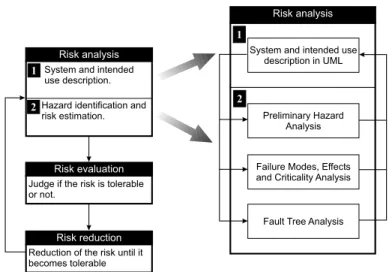
Today, as systems become more and more complex, safety is becoming critical. Safety, sometimes defined as an absolute property, can now be defined as the property of a system to be "free from unacceptable risk" [13]. Therefore it is necessary to reduce the risk to an acceptable level with a complete risk manage-ment activity as presented on figure 1. This approach has been used into different domains; and for exam-ple, some of its concepts can be found in the medical norm [12]. Inside the general risk management ac-tivity, our studies more precisely focus on risk anal-ysis. The justification of the use of the Preliminary Hazard Analysis (PHA), Failure Modes, Effects and Criticality Analysis (FMECA) and Fault Tree Anal-ysis (FTA) techniques is exposed in [8]. However, the reader can find developed the other aspects of risk analysis in [10, 9]. Those activities are based on a system model. Ideally, the system definition is mod-elled formally, but the use of formal methods in in-dustrial development of safe systems is still rare. A significant barrier is that many formal languages and formal analysis techniques are unfamiliar and difficult to understand and to apply for engineers. Designers must also communicate between specialists of differ-ent domains who usually have their own language. For these reasons, existing techniques must be
con-sidered. UML (Unified Modeling Language) notation fulfills these claims, and is now a standard in system and software engineering.
In this paper we will focus on the use of FMECA based on UML models in the risk analysis activity. The first section of this paper positions our works in the research communities on UML and risk anal-ysis. Section two and three expose our method based on UML message exchanges and present generic model of error after an analysis of message failure modes. The two following sections propose a generic FMECA array for a system analysis and validate this on an application to the analysis of messages send by actors such as external devices.
2.
Related works
The risk analysis activity recently appeared in the domain of computer systems safety. What one can found as a reference is the terminology about fault forecasting in [15]. It consists in anticipating faults using techniques to identify faults and evaluate their effects. This is close to risk analysis concept and par-ticularly to hazard identification and risk estimation activities. Thus, we focus on fault forecasting studies. Several research works can be found on the notion of component, considering that all components have in-puts and outin-puts (by analogy with electronics com-ponents). [24] identify software critical components evaluating the risk factor of each component consid-ering its complexity and the seriousness of its poten-tial failure. [23] also use component models, but use the HAZOP (Hazard Operability) analysis technique to automatically generate fault trees. These aspects meet the SIL (Safety Integrity Level) notion, used in norms [11], but cannot be applied to a system mod-eled with UML. Indeed, the notion of object is too far from the notion of component [5] to efficiently adopt a similar approach.
Nearer to the object paradigm and to UML, [6] define "critical attributes" of the system objects and study the effects of potential harmful variation of these attributes. This leads first to the notion of criti-cal sub-systems (which can be components) and
sec-Risk analysis
2
1 System and intended use description. Hazard identification and risk estimation.
Fault Tree Analysis Preliminary Hazard
Analysis
Failure Modes, Effects and Criticality Analysis System and intended use
description in UML
Risk analysis
2 1
Risk evaluation
Judge if the risk is tolerable or not.
Risk reduction
Reduction of the risk until it becomes tolerable
Figure 1 : UML based risk analysis in the risk management activity
ond to the identification of hazardous state based on statecharts ([18]). The approach is the same as the previous ones and consists in identifying parts of the system that might cause some damage. But the link between the very system objects are even more diffi-cult to evaluate.
Among analytical methods, allowing fault fore-casting, FMECA ([17]) is certainly the most used dur-ing functional analysis. Nevertheless, it can be ap-plied to software components and to their links [24]. This approach is similar to the study of electronics components but does not take into account the major object concepts as classes or methods. [1] suggests to use this technique analyzing the objects methods as a function analysis, and thus identifying effects on the system. In a case study on a car design,[14] use the UML use cases to specify requirements and realize a FMECA based on these diagrams. However, the link with UML is limited because the use cases identified, as the "car stability during braking", correspond to non-functional requirements and thus can not be used to identified objects.
Among analysis techniques, fault tree analysis must also be mentioned. This technique is usually coupled with a FMECA. [7] show how they use fault trees to express the different classes of faults of a model. The connection with the system objects is still complex, and the tree study seems to be done in par-allel without any real interaction with the UML mod-els. [22] presents a method and algorithms allowing to automatically generate fault trees from UML els. The resulting trees are in fact reliability mod-els to describe how a failure can occur in parallel to UML models. [2] also elaborated reliability models (Intermediate Model) based on UML diagrams, then derived into Timed Petri Nets [4, 16, 3]. All these techniques offer tools to designer and overcome some
UML weaknesses, as the lack of executing models. However, the techniques mentioned above strongly rely on the notion of component, which is different from the notion of object or class. On this very sub-ject, this paper shows how our approach distinguishes itself from these works, overall because it takes into account different concepts than the component con-cept.
3.
Message failure mode analysis
The notion of failure mode is close to the notion of error; both concepts will be indifferently used in this section.
The FMECA technique consists above all in identifying errors that could occur in a system be-fore its production. Actually, errors are often specific to the application. However, to realize a more sys-tematic error identification step, one can sometimes use some generic error models, which can be applied independently from the application. Unfortunately, these models often concern a few low level elements. Thus, we propose to focus on one of the language ele-ment which is not specific to an application: the mod-eling language itself, and in our approach we chose UML. Indeed, by analogy with electronics devices such as actuators and sensors, the modeling language constructions can be reused from an application to an-other. Moreover, this multidisciplinary language al-lows to model either electronic, computing, mechan-ical elements and even human actors. This generic-ity is thus double: it should allow to develop generic error models not only for different applications, but also for different domains (from electronics to human components).
Due to UML complexity, we focus on one con-struction of this language: the notion of Message.
Different reasons lead us to this choice. The goal of a failure analysis is to identify hazards during sys-tems use. It is a failure during an activity which lead to a hazard. And the activity of a model depends on the messages. Hazards occur when messages are ex-changed. In conclusion, we proceed to a failure anal-ysis based on messages and not on components or on functions.
However, focusing on the notion of Message can reduce the genericity. Indeed, the UML notation in-cludes the concept of Action which is the fundamen-tal element of the meta-model. Yet, in order to keep our approach close to UML user usual concepts, we preferred basing our approach on the Message notion. Moreover, current works on UML formalization show important differences on the Action concept. Indeed, version 1.5 of UML [21], strongly modified its previ-ous use (version 1.4 [19]). Furthermore, this specifi-cation differs from current works for version 2.0 [20]! On the other hand, the notion of Message seems sta-ble in those three documents; it just prove the force but also the importance of this concept.
4.
Message error models
This section presents the range of errors linked to the concept of Message that we have determined.
Some languages (such as Ada for example) con-tain an operational semantics and a verification se-mantics. The operational semantics allows to spec-ify a system functional aspects and describe how the system will deliver the service. This corresponds to the whole set of UML diagrams. The verification semantics defines properties to verify if some rules are respected. For example, in Ada, constraints on data variables of a software operative part can be ex-pressed. This semantics allows to identify errors re-sulting from a non-respect of one of these properties, and also permits to treat them. The possible process is thus to group all properties issued from the verifica-tion semantics and to derive error models from them. This approach can be applied to most of lan-guages, but usually, the verification semantics is ei-ther implicit, mixed into the operational semantics, either missing. In UML, a certain number of elements can be classified into the verification semantics. First, the use of constraints, graphically represented with curly brackets, allows to specify a restriction on the use of certain kind of elements; an error is raised if the constraint is not respected. There is also in the UML specification the Well-Formedness Rules which define a set of constraints expressed with the OCL language [19]. However, most of verification properties are not explicit; they are integrated into the operational se-mantics. To sum up and conclude on this point,
in-stead of trying to group the set of constraints or Well-Formedness Rules together relatively to the notion of Message, we propose to generally define the concepts inherent to the notion of Message. This approach syn-thesizes the elements specified in version 1.4 and al-lows to integrate elements such as time constraints, missing from the meta-model at the moment(work in progress by the OMG for UML version 2.0).
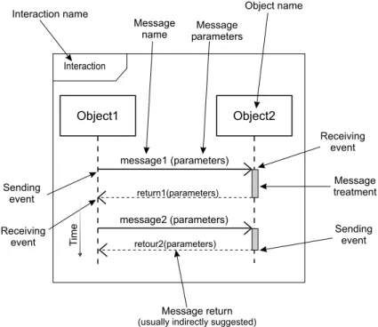
A message can be a signal creation, an opera-tion call, a creaopera-tion or destrucopera-tion of an instance; we thus present a generic description for all the charac-teristics of a Message. The graphical representation by a sequence diagram is illustrated on figure 2. The different elements of a message thus are here after de-fined:
1. the interaction it belongs ;
2. the next and previous messages in the interac-tion ;
3. the objects that send and receive the message ; 4. the sending and receiving events ;
5. the parameters (number, type and value) ; 6. the implicit response (defined by its arguments,
sending and receiving events) ; 7. the period of the message treatment.
Then possible errors for a message are established based on all these elements. First, a message belongs to an interaction, and a sending of a message non-planned is a type of usual error, which often happens in Human-Machine Interface manipulation. Gener-ally, this type of error can be extended with a first error model:
E.1. Sending of a message not belonging to the planned interaction.
The second point dealing with the message or-der can also lead to errors, particularly with human actors. Indeed, a user having many messages to send might inverse or forget one of them. This type of error can be extended to any model specifying two types of error:
E.2. Execution of one or several messages in a wrong order.
E.3. Omission of a message among an interaction.
A message is sent by an object, but the object supposed to receive it might not exit. This type of error, usual in computer sciences, allows to formulate a generic error:
Interaction
Object1 Object2
message1 (parameters)
message2 (parameters)
Interaction name Object name Message
name
Message return
(usually indirectly suggested)
Sending event Receiving event Message treatment Message parameters return1(parameters) retour2(parameters) Receiving event Sending event T ime
Figure 2 : Elements of an interaction realized by the exchange of two messages
E.4. Lack of an instance to receive the message.
Characteristics related to sending and receiving events allow to define temporal properties. Indeed, for these events, time is the fundamental element, and errors are caused by delays; messages can also be in advance compared to their specifications:
E.5. Sending or receiving of a message outside its specified time limits (too son or too late)
The message arguments constituting the oper-ation or called signal parameters must correspond (number, type and value) to those expected for the object receiver. This property, partially expressed in OCL by the Well-Formedness Rules of the UML spec-ification, allows the expression of tree types of errors:
E.6. The arguments type is different from the type of parameters expected by the receiver.
E.7. The number of a message arguments is dif-ferent from the number of parameters expected by the receiver.
E.8. The value of a message arguments is differ-ent from the value of parameters expected by the receiver.
The usual implicit answer to a message might be characterized by arguments (for example, an mes-sage which is an operation call, can return a value)
but also by some sending and receiving parameters. This leads to the identification of an error that is gen-erally relative to a message that call an operation (as for example ReadPosition for a position sensor):
E.9. The values returned by a response to a mes-sage does not fit with the expected values (for ex-ample: constant, random, out of limits, etc.)
The time of a message treatment correspond to the duration between the receiving of a message and the sending of a response. This response can either be a returned value, or the object contruc-tion/destruction, a signal emission, etc. This type of error can thus be identified:
E.10. Treatment of a message out of the specified time limits
Last but not least, in order to complete the el-ements that are mentioned on the diagram, we must also consider the link element, that characterizes the relation between the transmitter and receiver objects, and allows the message emission. This error type can thus be formulate:
E.11. Lack of link between sender and receiver objects
5.
Proposition of a generic FMECA
ar-ray for a system analysis
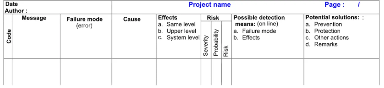
Based on the works and norms for FMECA as [17] (devoted to functional analyzes), this section pro-poses to introduce the following elements into the FMECA array (cf. figure 3) for a message failure mode analysis:
• the message name,
• the failure modes, or the errors identified thanks
to the previous error models,
• the causes of those failure modes,
• the effects at a local level, at a directly higher
level and at the system level,
• the data to estimate the risk (severity is the
dam-age seriousness, failure mode occurrence noted as probability, associated risk),
• the on-line means to detect failure modes and
their effects,
• the possible means of risk prevention and
pro-tection,
• other pieces of information.
Before explaining the approach, note that the goal in these arrays is not to proceed to a deep analy-sis of each of the mentioned points; in particular, it is not the point to consider the causes of the causes but to synthesize the main data in order to obtain a system analysis.
The column Potential solutions of the array on figure 3 deals with the possible means to reduce the risk. It is important to notice that these means are not directly implemented but this help to focus on the point that a preliminary risk evaluation must be done. Risk is here calculated from a qualitative estimation of the probability of occurrence of a failure mode and of the seriousness of the induced damage. We chose to represent the prevention and protection means but such an analysis can lead to other means. For exam-ple, having identified critical messages but for which estimating the probability of occurrence was difficult, a means to reduce the risk is to use fault removal tech-niques (verification, validation, tests, etc.). More gen-erally, the use of FMECA we propose does not follow a systematic process, where each failure mode is eval-uated in terms of probability and seriousness, then treated. The main reason comes from the impossi-bility to estimate the probaimpossi-bility of all failure modes, even in a quantitative way, as in the case of a software analysis. Thus, FMECA is essentially useful to fo-cus on critical and weak design points from the safety point of view.
: Master site Slave site movementcontroller
Control movements (parameters) Set the robot in initial position
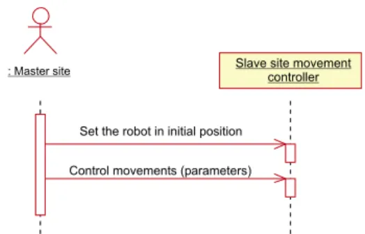
Figure 4 : Sequence diagram illustrating interactions
be-tween a master site and a slave site in a tele-medicine system
Finally, as FMECA directly depends on the model level of details, its use depends on the develop-ment process step applied. In our approach, we rec-ommend to concentrate on the first steps, when safety requirements, architecture choices and major hazards are identified.
6.
Application to the analysis of
mes-sages send by actors such as external
devices
A system approach must allow to take into account all components (electronics, informatics, mechanics and human factors) but it is obvious that only each field specialists really control data. However, as each one has his own language and his own techniques, it can be complex to group information in order to pro-ceed to a global analysis of a system. Using the UML language jointly to the message error models, permits to perform a risk analysis more homogeneous. This section presents an example of use of error models previously identified in order to demonstrate the fea-sibility of such an approach. This approach has been successfully applied to a complex medical robot sys-tem [8].
Objects and interactions modeling An actor char-acterizes an outside user or related set of users who interact with the system [5]. It is possible for an ac-tor to be a human user or an external subsystem. This section present an actor of the external device type. In the case of many systems, it is possible to represent external devices as actors if they interact with the sys-tem in an autonomous way. For instance, in the case of tele-medicine using robots, where a master site and a slave site interact, the slave site model might include the master site as an actor. The messages exchanged with the system can be modeled thanks to a collabo-ration or a sequence diagram as on figure 4.
Date Author :
Project name Page : /
Risk
C
o
d
e
Message Failure mode (error) Cause Effects: a. Same level b. System level c. Risk Possible detection means: (on line) a. Failure mode b. Effects Potential solutions: : a. Prevention b. Protection c. Other actions d. Remarks Probability Severity Upper level
Figure 3 : Example of FMECA array
Types of errors For an actor of the external device type, exchanged messages correspond either to oper-ations either to signals. Each error model from E.1 to E.10 can be used for these messages. As an exam-ple, for the message Control movements(parameters) of figure 4, errors can consist in sending wrong pa-rameters (error E.6, E.7 and E.8), they can be caused by delays (E.5 et E.10) or errors from the master site during the message emission (E.1, E.2, E.3, et E.4). For this type of actor, it is important to notice that the error types include the failures of the sender ob-ject, but also the failures of the link with the receiver object (E.11). This allows to consider the telecommu-nication aspects of some kind of application as tele-medicine.
Failure mode analysis The modeling of all ex-changed messages with sequence diagrams allows to process to an analysis very soon in the development process. It leads to formulate safety and reliability re-quirements from the start, with no need to develop the design choices to make components communi-cate. For example, on the diagram figure 4, the type of communication is not specified (intranet, internet, RS232, etc.), but failures of messages from the master site can be considered anyway.
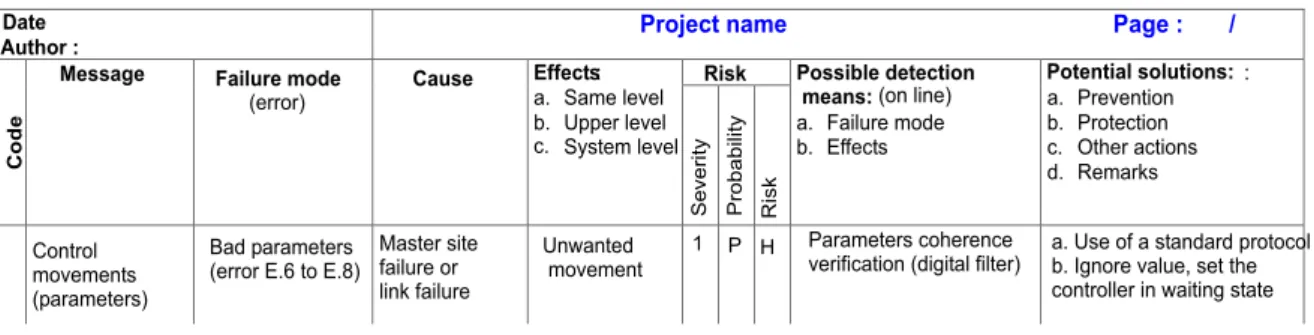
Figure 5 shows a generic analysis of the failure mode (E.6, E.7 or E.8 types) of the message Con-trol movement(parameters) of the sequence diagram on figure 4.
Then, from this analysis, one can propose a so-lution for this failure mode by the modification of the system UML diagrams. The solution we propose consists in temporarily changing the robot controller state. This is illustrated on the state diagram of fig-ure 6.
7.
Conclusions and perspectives
Considering the growing system complexity and the urgent need to take safety into account, we proposed an approach based on risk analysis. We considered that damages appear into a system because of its dy-namics. Thus, hazards are partially linked up with
IDLE
Moving
Pause
Task beginning Wrong parameters
Control_movements(parameters)
Delay expired/ Set in initial position
Control_movements(parameters) Valid parameters
Figure 6 : State diagram taking into account a failure mode
of Control movements()
message exchanges into a system. Going on the no-tion of Message in UML, we presented some mod-els of errors related to this concept. We showed that these models can also be useful in other fields (we validated it on the design of a highly critical tele-medicine application with robots [8]). Moreover, in other papers, we demonstrated that these models was generic and thus could be used for different applica-tions. The link between the object-oriented concepts and the FMCEA technique has been established, al-though the FMECA was originally dedicated to func-tional analysis. The approach we propose is inte-grated into a whole development process based on the UML notation where the risk analysis is devel-oped in parallel using the same UML models. The next technical step would be the development of tools to automatically integrated FMECA to UML design diagrams. Our theoretical perspective is to apply the same philosophy not to FMECA but to fault tree tech-nique.
References
[1] F. Bitsch. Requirements on methods and tech-niques in perspective to approval process for railway systems. In Second International Work-shop on Integration of Specification Techniques
Date
Author : Project name Page : /
Risk
C
o
d
e
Message Failure mode
(error) Cause Effects: a. Same level b. Unwanted movement c. Risk Possible detection means: (on line) a. Failure mode b. Effects Potential solutions: : a. Prevention b. Protection c. Other actions d. Remarks Probability Severity Upper level 1 Control movements (parameters) Master site failure or link failure Bad parameters
(error E.6 to E.8)
System level
P H Parameters coherence
verification (digital filter)
a. Use of a standard protocol b. Ignore value, set the controller in waiting state
Figure 5 : A failure mode analysis of the message Control movements()
for Applications in Engineering (INT 2002), Grenoble, France, April 2002.
[2] A. Bondavalli, M. Dal Cin, D. Latella, I. Majzik, A. Pataricza, and G. Savoia. Dependability anal-ysis in the early phases of UML based system design. International Journal of Computer Sys-tems - Science & Engineering, 16(5):265–275, September 2001.
[3] A. Bondavalli, I. Majzik, and I. Mura.
Au-tomated dependability analysis of UML de-signs. In 2nd IEEE International Symposium on Object-Oriented Real-time Distributed Com-puting (ISORC’99), Saint Malo, France, pages 139–144. IEEE Computer Society Press, 1999. [4] A. Bondavalli, I. Majzik, and I. Mura.
Auto-matic dependability analysis for supporting de-sign decisions in UML. In 4th IEEE High Assur-ance System Engineering Symposium (HASE99) Washington D.C., USA, pages 64–71. IEEE Computer Society Press, November 1999. [5] G. Booch, J. Rumbaugh, and I. Jacobson.
Uni-fied Modeling Language Users Guide. Addison Wesley Longman, 1999.
[6] J. Górski and B. Nowicki. Object oriented safety monitor synthesis. In D. Gritzalis, editor, Third International conference on reliability, quality and safety of software intensive systems (EN-CRESS’97), Athens, Greece, pages 121–133. Chapman and Hall, May 1997.
[7] J. Górski, B. Nowicki, and A. Wardzinski. Holistic and partial system models in safety analysis. In International conference on prob-abilistic safety assessment (PSA’96), Park City, USA, volume 2, pages 1301–1309, September 1996.
[8] J. Guiochet. Safety management of service robot systems - UML approach based on system risk analysis (in french). PhD thesis, Institut Na-tional des Sciences Appliquées de Toulouse, 2003.
[9] J. Guiochet, B. Tondu, and C. Baron. Integration of UML in human factors analysis for safety of a medical robot for tele-echography. In Proc. of the IEEE/RSJ International Conference on In-telligent Robots and Systems, InIn-telligent Robots and Systems for Human Security, Health, and Prosperty IROS 2003, October 2003. accepted. [10] J. Guiochet and A. Vilchis. Safety analysis of
a medical robot for tele-echography. In Proc. of the 2nd IARP IEEE/RAS joint workshop on Technical Challenge for Dependable Robots in Human Environments, Toulouse, France, pages 217–227, October 2002.
[11] IEC 61508. Functional safety of
electri-cal/electronic/programmable electronic safety-related systems. International Electrotechnical Commission, 2001.
[12] ISO 14971. Medical devices - Application of risk management to medical devices. Interna-tional Organization for Standardization, 2000. [13] ISO/IEC Guide 51. Safety aspects - Guidelines
for their inclusion in standards. International Organization for Standardization, 1999. [14] P. Johannessen, C. Grante, A. Alminger, U.
Ek-lund, and J. Torin. Hazard analysis in object ori-ented design of dependable systems. In 2001 In-ternational Conference on Dependable Systems and Networks, Göteborg, Sweden, pages 507– 512, July 2001.
[15] J-C. Laprie. Dependability: Basic concepts
and terminology in English, French, German, Italian and Japanese, volume 5 of Depend-able Computing and Fault Tolerance. Springer-Verlag, Austria, 1992.
[16] I. Majzik and A. Bondavalli. Automatic
de-pendability modeling of systems described in
UML. In R. Chillarege, editor, 9th
Interna-tional Symposium on Software Reliability Engi-neering (ISSRE’98), Paderborn, Germany,
vol-ume 2, pages 4–7. Th. Illgen, IEEE Computer Society, November 2000.
[17] MIL-STD-1629A. Procedures for performing a Failure Mode, Effects and Criticality Analysis. Military Standard, 1980.
[18] B. Nowicki and J. Górski. Object oriented safety analysis of an extra high voltage substation bay. In W. Ehrengerber, editor, SAFECOMP’98, pages 306–315. Springer-Verlag, 1998.
[19] OMG. OMG Unified Modeling Language Spec-ification v1.4. Technical report, Object Manage-ment Group, September 2001.
[20] OMG. 2nd revised submission to OMG RFP ad/00-09-02 - Unified Modeling Language :
Su-perstructure - version 2.0. Technical Report
ad/2003-01-02, Object Management Group, January 2003.
[21] OMG. OMG Unified Modeling Language Spec-ification v1.5. Technical Report formal/03-03-01, Object Management Group, March 2003. [22] G.J. Pai and J.B. Dugan. Automatic synthesis of
dynamic fault trees from UML system models. In Proceedings of the 13th International Sym-posium on Software Reliability Engineering (IS-SRE’02), 2002.
[23] Y. Papadopoulos and M. Maruhn. Model-based automated synthesis of fault trees from matlab-simulink models. In Int. Conf. on Distributed Systems and Networks (DSN’2001), Gothen-burg, Sweden, pages 77–82, 2001.
[24] S. Yacoub, H. Ammar, and T. Robinson. A
methodology for architectural-level risk
anal-ysis. In 11th International Symposium on
Software Reliability Engineering (ISSRE’2000), San Jose, CA, pages 210–221, October 2000.
Biography
JEREMIE GUIOCHET studied electronics and com-puter sciences at ENSEIRB, a French engineering school based in Bordeaux. He ob-tained his degree in 1998 and came in Toulouse to start his research in the LESIA labo-ratory. He received the Ph.D. in 2003 from the INSA, Toulouse, France. He is now an associate profes-sor in Computer Science in University of Toulouse III. He does his research both in LESIA and in GRIMM/ISYCOM. His research interests are in the areas of software modeling and safety critical systems and particularly medical robots.
Contact : [email protected] http://www.lesia.insa-tlse.fr/ guiochet
CLAUDE BARON was born in Perpignan, France, and went to the National Institute of Applied Sciences of Toulouse to study com-puter sciences. She obtained her degrees in 1992 and her PhD in 1995. She is now an assistant professor at INSAT where she teaches real time systems and system reliability. She does her research at the LESIA laboratory where she is in charge of the SFS group.
Contact: [email protected]
http://www.lesia.insa-tlse.fr/francais/membres/p-pers/baron-claude/index.html