IN SITU STUDIES OF VOLATILE MOLECULES TRAPPING IN ZIRCONIUM ALLOY-BASED NON-EVAPORABLE GETTER
ZEINAB ABBOUD
DÉPARTEMENT DE GÉNIE PHYSIQUE ÉCOLE POLYTECHNIQUE DE MONTRÉAL
MÉMOIRE PRÉSENTÉ EN VUE DE L’OBTENTION DU DIPLÔME DE MAÎTRISE ÈS SCIENCES APPLIQUÉES
(GÉNIE PHYSIQUE) DÉCEMBRE 2016
ÉCOLE POLYTECHNIQUE DE MONTRÉAL
Ce mémoire intitulé:
IN SITU STUDIES OF VOLATILE MOLECULES TRAPPING IN ZIRCONIUM ALLOY-BASED NON-EVAPORABLE GETTER
présenté par : ABBOUD Zeinab
en vue de l’obtention du diplôme de : Maîtrise ès sciences appliquées a été dûment accepté par le jury d’examen constitué de :
M. DESJARDINS Patrick, Ph. D., président
M. MOUTANABBIR Oussama, Ph. D., membre et directeur de recherche M. CHARETTE Paul, Ph. D., membre externe
DEDICATION
To Hala Ghazi,
Who was persistently pursuing her education until her last breath May she rest in peace
ACKNOWLEDGEMENTS
I would like to express my deepest gratitude to individuals without whom this work would not be possible. First and foremost, to my supervisor Prof. Oussama Moutanabbir, for your trust, guidance, and support, this work and the progress I made in the past two years would not have been possible. Thank you. I would like to thank Professors Patrick Desjardins and Paul Charette for taking the time to review and provide input and suggestions to improve my thesis.
I sincerely thank my Polytechnique family, my colleagues, my friends, who have helped me throughout the past two years, brought joy, and so much laughter into my life. Thank you, to all of you, you have all contributed in one way or another in making this journey easier, and more enjoyable. Thanks to all the support staff from LMF, GCM, and Université de Montréal, your help and assistance have had tremendous influence on progressing my work. I would especially like to thank Josianne Lefebvre, who I am extremely grateful for, for her help, advice, and stress-relieving chats. Special thanks to Olga for dragging me out of my thesis cave whenever she got a chance to, the few times that I had taken a break from writing, were tremendously helpful in keeping me sane. Thank you. The work presented in this thesis would not have been possible without the help and input from collaborators from Teledyne DALSA Semiconductor, C2MI, and Université de Sherbrooke. Special thanks to Pascal Newby for his support and valuable input on this work. Thanks to Cédrik Coia for his advice. Cedric Spits, Jean-Sebastien Poirier, Jonathan Lachance, Luc Fréchette, Jean-Philippe Dery and Maxime Biron, thank you all for your time and help.
Nothing would have been possible without the endless support of my parents; mother, father, thank you for your faith in me and your prayers. My brothers, thank you for your help, and your little bundles of joy that always bring me happiness, no matter how short and seldom my visits were. Special thanks to my sister, Khadige, whose support and advice has brought me hope, no matter how harsh it was. I wish you all the best in your career, you deserve it. Thanks to my little twin-10 sister, Fatima, for all the laughter and cheesy comments. Best of luck in your next phase in life! I hope it will be full of success and joy.
My friends, Sarah and Malak, despite the distance, and the time we have been apart, you have always been, and remain to be true friends, thank you for all your support. Thanks to Judy, Anand, Jafar, and Mohamed for all your support and patience with me all these years. And last but not least, to Eugene, thank you for listening.
RÉSUMÉ
La demande pour le maintien du vide et l'expulsion de gaz résiduels dans les micro-cavités dans les systèmes microélectromécaniques (MEMS) et dans d’autres dispositifs micro-fabriqués a augmenté significativement lors des dernières années.. Les gaz résiduels empoisonnent souvent le vide et finissent par détériorer le fonctionnement des dispositifs. Afin de maintenir le vide dans les cavités, quelques étapes doivent être mises en œuvre: i) une étanchéité hermétique de la cavité doit être réalisée pour éliminer les fuites de gaz; ii) un dégazage approprié du système pour déloger et libérer les gaz piégés dans les matériaux est nécessaire avant de sceller de la cavité; Et iii) si nécessaire, incorporer une bande ou une couche mince d'un alliage métallique réactif agissant comme pompe chimique pour débarrasser le système des gaz résiduels pendant le fonctionnement du dispositif. De tels alliages sont connus sous le nom de getters, formés entre autres de métaux de transition actifs tels que Zr, Ti, V et Fe qui chimisorbent spontanément les gaz actifs dans les cavités. Pour améliorer l'efficacité de l'adsorption, une variété de systèmes de matériaux ont été proposés et testés, et deux caractéristiques semblent être critiques: (1) la morphologie (aire de surface); Et (2) la composition (réactivité physique et / ou chimique). Malgré leur importance technologique, peu de choses sont connues sur les mécanismes exacts de piégeage de gaz dans les matériaux. Ce projet aborde cette question en se basant sur des études in situ pour élucider la nature des réactions entre les constituants getters et les gaz résiduels et l'effet de la température d'activation sur la composition de surface et le piégeage des molécules volatiles.
Nos études ont porté sur les alliages de zirconium-cobalt-terres rares (REM) qui ont été conçus pour avoir une basse température d'activation (<350oC) compatible avec les processus de fabrication et d’intégration de certains dispositifs MEMS. Des couches minces de ces alliages ont été pulvérisées sur Si. Les films obtenus sont très poreux, ce qui est critique pour réduire la température d'activation. La microscopie électronique à balayage (SEM), la spectroscopie de photoélectrons X (XPS), la spectrométrie de masse d'ions secondaires au temps de vol (TOF-SIMS) et la détection de recul élastique en temps de vol (TOF-ERD) ont été utilisées afin d’examiner la morphologie et la composition de la surface et du matériau massique. L'évolution de la surface en fonction de la température a été analysée in situ via XPS. Ce travail propose des mécanismes détaillés expliquant la réactivité à température ambiante et à haute température du matériau avec O2, N2 et CO2.
Les résultats montrent que l’activation débute à 200oC et n’est que partielle à 350oC. Le
processus d'activation thermique entraîne la réduction partielle de ZrO2, la réduction totale de
l’oxyde de Co et n'a aucune influence sur l’état des REM. Des études en fonction du temps et de la température montrent que la diffusion d'oxygène de la surface vers le volume est activée thermiquement avec une énergie d'activation de 0,21 ± 0,02 eV. L'exposition de la surface partiellement activée à O2 à une pression de 10-5 Torr pendant 30 minutes a été trouvée suffisante
pour saturer la surface, d'autre part l'exposition de N2 n’a eu aucun impact sur la chimie de surface.
Les espèces N-apparentées apparaissent seulement après des expositions à haute température du matériau, montrant la réactivité limitée du getter avec N2. CO2 conduit à la formation de
monocouches de CO sur la surface du getter et à la diffusion de O2- dans le volume du matériau.
Ces résultats indiquent la réactivité élevée du getter avec des gaz contenant de l'oxygène, mais une réactivité plutôt limitée avec N2. Un mécanisme de diffusion de l'oxygène vers le volume ainsi
qu’un mécanisme de piégeage des gaz sont proposés. Les résultats donnent un nouvel aperçu des avantages et des limites du getter pour les applications MEMS.
ABSTRACT
Recently, there has been an increasing interest in vacuum maintenance and residual gases expulsion within small cavities in microelectromechanical systems (MEMS) and advanced field emission displays. Residual gases often poison the vacuum and eventually deteriorate device and system operation. In order to maintain vacuum in cavities, there are a few steps that must be implemented: i) a hermetic sealing of the cavity should be realized to minimize gas leakage from surrounding environment; ii) proper degassing of the system before seal-off is needed to dislodge and release trapped gases within the materials; and iii) if necessary incorporating a strip or a thin film of a reactive metal alloy which acts as a chemical pump to rid the system of residual gases during the device lifetime. Such alloys are known as getters, which contain active transition metals such as Zr, Ti, V, and Fe that spontaneously chemisorb active gases within cavities. To improve the gettering efficiency, a variety of material systems have been proposed and tested, and two characteristics appear to be critical: (1) morphology (surface area); and (2) composition (physical and/or chemical reactivity). Despites their technological importance little is known about the exact mechanisms of gas trapping within the material. This project tackles this very issue by using in situ studies to investigate the nature of bonding between the getter constituents and residual gases and the effect of the activation temperature on the surface composition and volatile molecules trapping. Our studies focused on zirconium-cobalt-rare earth metal (REM) alloys which have been developed with a low activation temperature (<350oC) for MEMS devices. Thin films of these alloys were sputtered on Si. The obtained films are highly porous, which is critical to lower the activation temperature. Scanning Electron Microscopy (SEM), X-ray Photoelectron Spectroscopy (XPS), Time of Flight Secondary Ion Mass Spectrometry (TOF-SIMS), and Time of Flight Elastic Recoil Detection (TOF-ERD) are utilized to examine the morphology and composition of both bulk and surface of the alloy. The surface evolution as a function of temperature is monitored in situ via XPS. This project elucidates the room temperature and high temperature reactivity of the material with O2, N2, and CO2.
The results show that annealing at 350oC only leads to a partial activation of the surface, with an onset at 200oC. The thermal activation process results in the partial reduction of ZrO2, full
reduction of Co from its oxide state and has no influence on REM states. Time and temperature-dependent studies show that oxygen diffusion from surface to bulk is thermally activated with an
activation energy of 0.21±0.02 eV. Exposure of the partially activated surface to O2 at a pressure
of 10-5 Torr for 30 minutes was found to saturate the surface, on the other hand N
2 exposure was
found to have no impact on the surface chemistry. N-related species were only apparent at high temperature exposures of the material, displaying the limited reactivity of the getter with N2. CO2
results in the formation of CO monolayer on the surface of the getter with the diffusion of O2- to the bulk of material. These results indicate the high reactivity of the getter with oxygen-containing gases, but a rather limited reactivity with N2. A mechanism of oxygen diffusion to the bulk as well
as for trapping of gases are proposed. The results give new insights into the advantages and limitations of the material for MEMS applications.
TABLE OF CONTENTS
DEDICATION ... III ACKNOWLEDGEMENTS ... IV RÉSUMÉ ... V ABSTRACT ...VII TABLE OF CONTENTS ... IX LIST OF TABLES ... XI LIST OF FIGURES ...XII LIST OF ABBREVIATIONS ... XV LIST OF APPENDICES ... XVICHAPTER 1 INTRODUCTION ... 1
1.1 Context ... 1
1.2 Thesis Objectives & Outline ... 3
CHAPTER 2 CRITICAL REVIEW OF THE LITERATURE ... 5
2.1 Getter ... 5
2.1.1 Classification ... 6
2.1.2 Gettering Principle of Operation ... 7
2.1.3 Current Status of Getter ... 10
2.2 Zr: Chemistry, Reactivity, & Applications ... 16
CHAPTER 3 EXPERIMENTAL TECHNIQUES ... 18
3.1 X-ray Photoelectron Spectroscopy ... 18
3.1.1 Overview ... 18
3.1.2 Set up & Theoretical background ... 19
3.2 Time-of-Flight Secondary Ion Mass Spectrometry ... 25
3.3 Time-of-Flight Elastic Recoil Detection ... 25
CHAPTER 4 RESULTS AND GENERAL DISCUSSION ... 27
4.1 Abstract ... 27
4.2 Experimental details ... 28
4.3 Results and Discussion: ... 29
4.3.1 Structure and chemical composition of the getter ... 29
4.3.2 Activation process and its effects on surface composition ... 34
4.3.3 Kinetics of the getter activation ... 42
4.3.4 Oxygen Trapping ... 46
4.3.5 Nitrogen Trapping ... 49
4.3.6 Carbon Dioxide Trapping ... 53
4.4 Conclusions ... 56
CHAPTER 5 CONCLUSION AND PERSPECTIVE ... 58
REFERENCES ... 61
LIST OF TABLES
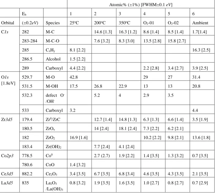
Table 2.1: List of non-evaporable getter materials examined in the literature, the deposition technique, their activation temperature, and the targeted application. ... 12 Table 4.1: Summary of XPS analysis of the alloy surface at (1) 25oC (2) 200 oC. (3) 350 oC. (4) cooled down to 25 oC and dosed with 1.8×10⁴ L of O2 (30 min at 1×10⁻⁵ Torr). (5) Sample 4
dosed with an additional 3.6 ×10⁴ L of O2. (6) Sample 5 stores in ambient conditions for 1
week. (spectra shown in Figure 4.3). M = Metal ... 36 Table 4.2. Summary of fitting parameters for the decay of XPS signal for O1s as a function of temperature. ... 44 Table 4.3. Analysis for XPS spectra shown in. Figure 4.8. (1) as received (2) 350 oC + O2 (10-5
Torr, 50 min) (3) Sample 2 stored in ambient conditions (4) New sample heated to 350 oC and dosed wtih N2 (10-5 Torr, 50 min) and cooled down to 25oC (5) Sample 4 stored in ambient
conditions. M = Metal. ... 48 Table 4.4. Semi-quantitative analysis of ARXPS data for examining surface reactivity with CO2 in
LIST OF FIGURES
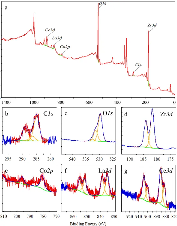
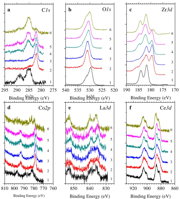
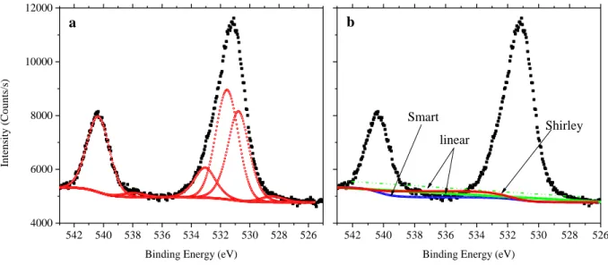
Figure 2.1: Schematic representation of the thermal activation process for non-evaporable getter alloy. (a) Shows the grains of the alloy material, with a passivating layer of contaminants encapsulating the entire surface of the material (red spheres) l. (b) Annealing the alloy to a critical activation temperature allows for surface contamination to diffuse to the bulk of the material freeing up surface sites for subsequent gettering. ... 8 Figure 3.1: (Left) Energy band diagram representation of the photoelectric emission process. A core level electron absorbs a photon of energy hv, resulting in the emission of the photoelectron with kinetic energy KE. (adapted from [142]) (Right) Schematic representation of a conventional XPS set up, presenting the X-ray source, the sample, electron analyzer and the detector. (reproduced from [151]). ... 20 Figure 3.2: XPS spectrum of a polycrystalline Zr surface, generated using Al Kα X-ray source. 22 Figure 3.3: High resolution XPS signal (black trace), with deconvoluted peaks for Sb3d and O1s signals. (a) showing the deconvoluted peaks for the sub-species, (b) background subtraction using linear, Shirley and Smart methods. ... 24 Figure 3.4: Schematic representations of (a) TOF-SIMS (adapted from [156]) and (b) TOF-ERD (adapted from [159]). ... 26 Figure 4.1:(a) SEM image of as received alloy. The inset is a close-up SEM image providing more details on the morphology of the alloy under investigation, (b) TOF-SIMS depth profile of alloy film constituents, with O- signal shown in inset for clarity, and (c) TOF-ERD concentration profile of the important constituents in as received alloy (uncertainty ±1 at.%). ... 31 Figure 4.2: XPS of Zr-Co-REM alloy (a) Complete spectrum of as-received alloy, high resolution spectra of (b) C1s, (c) O1s, (d) Zr3d, (e) Co2p, (f) La3d, and (g) Ce3d. (red = raw counts, blue = fit, yellow = deconvoluted peaks, green = subtracted background) ... 33 Figure 4.3: Evolution of normalized XPS spectra of (a) C1s, (b) O1s, (c) Zr3d, (d) Co2p, (e) La3d, and (f) Ce3d orbitals under the following consecutive treatments: (1) As received. (2) Annealed at 200 oC. (3) annealed at 350 oC. (4) sample cooled down to 25 oC and exposed to
1.8×10⁴ L of O
2 (30 min at 10-5 Torr). (5) Sample #4 exposed to 3.6 ×10⁴ L of O2. (6) Sample
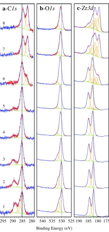
#5 stored in ambient conditions for 1 week. ... 35 Figure 4.4: Evolution of normalized high resolution XPS spectra as a function of temperature of (a) C1s, (b) O1s, and (c) Zr3d orbitals. (1) 25oC, (2) 50oC, (3) 100oC, (4) 150oC, (5) 200oC, (6) 250oC, (7) 300oC, (8) 350oC. (red line represent raw data, blue line represents the overall fit, the deconvoluted peaks are represented by yellow traces, and the background is denoted by green lines). ... 38 Figure 4.5: (a) Shift in binding energy with respect to room temperature upon thermal annealing for C1s, O1s and Zr3d, vs. temperature (ΔE = BET –BE25oC). (b) Atomic concentration as
evaluated by XPS measurement of C1s, O1s, and Zr3d orbitals as a function of temperature (±1%). ... 39 Figure 4.6: Integrated XPS signal evolution for: (a) C1s, (b) Zr3d and (c) O1s annealed at (1) 200
oC, (2) 250 oC, (3) 300 oC, (4) 330 oC, (5) 350 oC. (d) Arrhenius plot of the diffusion rate for
O. (e) Evolution of XPS intensity for O, Zr at 250 oC. (f) Oxide thickness vs. time and temperature (±0.2 nm). ... 43 Figure 4.7: TOF-ERD depth profiles of getter sample (a) as-received, (b) treated in RTA at 400 oC under Ar for 30 min. ... 45 Figure 4.8: Evolution of normalized XPS spectra of (a) C1s, (b) O1s, (c) N1s, (d) Zr3d, (e) Co2p, (f) Ce3d and La3d orbitals; (1) as received (2) sample heated to 350oC in the presence of O
2
(10-5 Torr for 50 min) followed by cooling to room temperature under UHV (3) Sample 2
stored in ambient atmosphere (4) A new sample heated to 350oC under N2 (10-5 Torr - 50 min)
followed by cooling to 25oC under UHV (5) Sample 4 stored in ambient conditions. ... 46 Figure 4.9: (a) Integrated XPS intensity for sample undergone repeated annealing at 350 oC ( ), cooling to 25oC (no line), and dosing with N2 (10-5 Torr – 20 min) ( ). (b) Evolution of N1s
signal as the sample undergone multiple annealing and nitriding steps (black = baseline measurement, red = 350 oC, green = N2 (1.2×10⁴ L – 25 oC)). (c) Evolution of normalized
XPS intensity for N1s under several cycles of N2 dosing at 25 oC ( ), annealing at 350 oC (
Figure 4.10: Evolution of normalized XPS spectra of (a) C1s, (b) O1s, (c) Zr3d, for samples under the following conditions: (1) untreated, (2) annealed at 350 oC, (3) sample #2 cooled down to
25 oC and dosed with 1.8×10⁴ L of CO2 measured at 0o take off angle. ARXPS measurements
on sample #3 (4) 40o, (5) 60o, (6) 80o. (7) Sample #3 heated to 350 oC and measured at 0o and (8) 80o take-off angles. (9) Sample #7 cooled down to 25 oC, (10) exposed to 1.8×10⁴ L of CO2 and measured at 0o, (11) 40o, (12) 60o, and (13) 80o. ... 55
LIST OF ABBREVIATIONS
ABBREVIATIONS
AES Auger Electron Spectroscopy BCC Body Center Cubic
HCP Hexagonal Close-Packed NEG Non-Evaporable Getter
SEM Scanning Electron Microscope TDS Thermal Desorption Spectrometry TOF-ERD Time-of-Flight Elastic Recoil Detection
TOF-SIMS Time-of-Flight Secondary Ion Mass Spectrometry XPS X-ray Photoelectron Spectroscopy
LIST OF APPENDICES
APPENDIX A EVOLUTION OF XPS SPECTRA OF POLYCRYSTALLINE ZIRCONIUM.. 79 APPENDIX B ... 80 ARTICLE I: TEMPERATURE-DEPENDENT IN SITU STUDIES OF VOLATILE MOLECULE TRAPPING IN LOW TEMPERATURE-ACTIVATED ZR ALLOY-BASED GETTERS ... 80
CHAPTER 1
INTRODUCTION
1.1 Context
Developing materials for gas trapping and storage is of utmost importance for several technologies including; clean energy applications[1], [2], noble gas separation[3], [4], carbon sequestration[5], [6], and removal of residual gases in vacuum cavities or chambers[7]–[10]. Such materials are very reactive and specifically designed with high porosity, nano- and micro-sized pores, to allow high gas sorption capacities[5], [11], [12]. Their functionality and gas selectivity can be tailored through material design and engineering for specific applications. Structural selectivity rises from the pore size distribution within the material that preferentially traps certain molecules. This behavior, which is governed by the steric effect, is known as “molecular sieving”[13]–[15]. “Quantum sieving” is a particular case of the molecular sieving effect, where the diameter of the pore is in the sub-nanometer range[14], [16]. Chemical selectivity, on the other hand, originates from the nature of interaction between impinging gas molecules and atoms present on the surface, which is governed by thermodynamics constraints[13]. Kinetics can also play an important role in selective interaction, where different gases have different diffusion rates depending on the adsorbent material[14], [15]. Materials designed for gas trapping include metal-organic frameworks[3], [11], [14], [17], carbon-based materials[5], [18], polymeric networks[5], [19], transition metal alloys[9], and alkaline earth metal alloys[8].
Transition and alkali earth metal alloys are used as getter materials for residual gas removal in vacuum chambers[9], [10], [20]. These materials are capable of sorbing a wide range of gases at room temperature. They are able to irreversibly trap O2, N2, H2, CO, CO2, H2O, and
hydrocarbons[20]. There are two main classifications of getter materials: evaporable (flashed), and non-evaporable (bulk getters). The former is composed of an alloy or pure metal (e.g. BaAl4, Ti,
Ni) in powder or bulk form, which is cyclically sublimated within the chamber, while the latter is deposited as a film of a few micrometers (<5 μm) in thickness and is often composed of transition metal alloys [20]–[22]. Flashed getters react with residual gases by sublimation (>1000oC) and
condensation on the inner walls of the vacuum chamber[21], [23], [24]. On the other hand, bulk getters are deposited prior to forming the vacuum cavity and are then thermally activated (<500oC)
accelerators[26], and microelectromechanical systems (MEMS) vacuum packaged devices[8], [27]–[29].
Bulk getters were developed for vacuum chambers or cavities that are incompatible with the continuous evaporation of materials, and cannot withstand the high temperatures at which flashed getters are sublimated (>1000oC)[8], [21], [27]. Bulk getters are often integrated in vacuum
packaged MEMS devices for maintaining proper operating conditions for the lifetime of the device (10+ years)[29], [30]. The vacuum requirement varies depending on the application and ranges between 10-4-225 Torr[27]. Considering a hermetically sealed cavity (i.e. no leakage), material
outgassing would be the only source of pressure increase within MEMS cavities[31]. The material is generally sputter deposited on the cap wafer for wafer-level packaging prior to wafer bonding[27]. However, the material remains inactive due to the formation of an oxide layer on the surface upon exposure to ambient condition. The oxide acts as a passivation layer preventing further oxidation of the material and diffusion of gases to the bulk. Thus, the surface must be activated during or after formation of the microcavity. The activation process must also be compatible with the thermal budget required to maintain the device operation.
In order to activate the getter, the material is annealed to a critical temperature at which the oxide and other contaminants would diffuse into the bulk freeing up surface sites to interact with residual gases[21]. The activation temperature changes depending on the composition of the material, and can range between 200-400oC[32]–[34]. The overall sorption capacity of the material
is limited by the available surface area, which is dependent on the morphology of the thin film[26]. Bulk getters are mainly composed of zirconium due to its highly electropositive nature and innate ability to dissolve its own oxides, carbides, and nitrides upon annealing[35]–[37].
Despite their technological importance, to the best of our knowledge, no detailed study has been conducted on the kinetics and the underlying mechanisms of gas trapping and surface contaminant diffusion into the bulk of a Zr-Co-REM (rare earth metals) getter material. in situ X-ray photoelectron spectroscopy (XPS) has been utilized to study the activation process of various getter materials due to its high surface sensitivity[38]–[47]. Petti et al.[47] and Xu et al.[30] investigated the influence of annealing temperature up to 450oC on the surface chemistry and
microstructure from engineering and industrial perspectives. Petti et al. concluded that the Zr-Co-REM getter is activated at 300oC by reducing the ZrO
of Co towards the surface at 450oC. On the other hand, Xu et al. examined the effect of annealing
temperature on the microstructure, as well as the resistance of the getter to various wafer cleaning processes by examining the getter’s sorption characteristics [30]. Despite the recent efforts in providing a complete study of the gettering properties of the Zr-Co-REM alloy, a rigorous study of the physical and chemical characteristics of the alloy are still missing. The studies also lack an examination of trapping of common residual gases within MEMS cavities, especially N2, since
many industrial processes are conducted in an N2 environment, increasing the partial pressure of
N2 within cavities. Therefore, it is of utmost importance to understand and quantify the ability of
the Zr-Co-REM getter of trapping N2, along with other volatile molecules.
1.2 Thesis Objectives & Outline
The brief overview above highlights the importance of understanding the characteristics of getter materials at the micro- and nano-scale in order to improve material performance for targeted applications. This thesis focuses on understanding the mechanism in which gases are trapped in a Zr-Co-rare earth metal (REM) alloy based getter that has been recently developed for MEMS applications. The main objectives and addressed questions in this thesis are as follows:
Elucidation of the influence of low temperature activation on the alloy surface chemistry.
Investigations of the kinetics of oxygen diffusion from surface to bulk of the material. Qualitative and quantitative studies of the reactivity of the getter with O2, N2, and CO2
molecules.
The thesis is organized in the following manner:
Chapter 2 gives the scientific and technological background of the development of getters as well as the theoretical basis of their operation, their classifications, and specific examples from the broad spectrum of their applications.
Chapter 3 describes the experimental techniques employed in this work, including XPS, TOF-SIMS, and TOF-ERD.
Chapter 4 discusses the experimental results obtained from in situ XPS and ex situ TOF-SIMS and TOF-ERD studies of the getter activation and reactivity (manuscript submitted to Journal of Physical Chemistry)
Chapter 5 summarizes the important findings and identifies key points that need to be addressed in future projects.
CHAPTER 2
CRITICAL REVIEW OF THE LITERATURE
2.1 Getter
Getter is a term that describes materials that are capable of chemically absorbing (sorbing) active gases. In the late 19th century, Malignani, Thomas Edison’s assistant, used the term “getter” to describe red phosphorous in incandescent lamps [36], [48]. Red phosphorous was used to prevent the blackening of incandescent lamps, which was due to the deposition of tungsten oxide on the inner walls of the lamp. Tungsten oxide forms as a result of tungsten evaporation from the hot filament and its reaction with residual water vapor within the bulb [49]. Evaporation of tungsten from the hot filament is known as thermionic emission or Edison effect, and efforts to prevent this phenomenon have led to the development of vacuum tubes [48]. The integration of phosphorous as a getter was able to reduce the level of water vapor within incandescent lamps, and therefore increase the lifetime of the bulbs. Then, in the early 1900s, with the development of electron tubes, great effort was put into increasing their lifetimes. After the Second World War, a study was conducted on the causes of failure in electron tubes and it was found that poor vacuum was the main culprit. Barium (Ba) was then incorporated in an effort to maintain vacuum within the tube. The result was a dramatic increase in the lifetime of the tube to tens of thousands of hours (500% increase) [48].
Commercialized getters were developed by SAES Getters S.p.A.. and Telefunken companies in Italy and Germany in the late 1940’s and early 1950’s [50]. Getters are composed of materials that naturally allow for the adsorption, absorption, and dissociation of gases. They are widely utilized in vacuum systems in order to either improve or maintain a level of vacuum, or to purify inert gases within a particular system. They are capable of irreversibly trapping reactive gases such as O2, H2, N2, CO2, CO, H2O, and hydrocarbons, but not noble gases [21], [24], [51], [52]. Getter
materials are able to produce stable solid compounds by chemically reacting with residual gases forming oxides, nitrides, carbides, hydroxides, and hydrides [21]. Getters are increasingly utilized in many applications including but not limited to the following; particle accelerators for extreme high vacuum [33], lighting applications [53], vacuum microcavities in MEMS [8], [36], [54], [55],
flat-panel displays [22], ultrahigh vacuum systems [24], [51], [56], and inert gas purification [45], [57].
In the following sections, the different types of getters, the principles of their operation, and the materials used for gettering will be discussed.
2.1.1 Classification
The first class of getter material developed, which was briefly mentioned earlier, was Ba for electron tubes and cathode ray tubes. Ba-based getters were initially used as pure metal in bulk form. However, they were unstable due to the high reactivity of Ba with water vapor and O2
rendering it unstable and difficult to handle. In the early 1950’s della Porta of SAES group in Italy solved this issue by alloying Ba with aluminum (Al), BaAl4, allowing the material to pump for
increasingly longer hours while being more easily handled [21], [36]. Ba alloy is part of the class of getters that are used for high temperature applications, where the material is heated to substantially high temperatures (>1000oC). The heat treatment results in the evaporation of the
material, which would then react with residual gases and condensate on the inner walls of the chamber as a thin film. Today, titanium (Ti) sublimation pumps operate on the same concept [23], [58], [59]. This class of materials is known as evaporable (flashed) getters [21], [50]. The evaporation cycle can be repeated many times during the lifetime of the device or chamber to maintain proper operating conditions [21]. Due to the volatile nature of evaporable getters and the high temperatures at which they are sublimated, another class of materials was developed in the late 1950’s known as non-evaporable getters [60]. These materials are deposited as thin films prior to the formation of the vacuum cavity or chamber and operate at much lower temperatures (<700oC) [21], [50], [60]. Recent progress in developing different materials for non-evaporable getters has sparked a surge of studies to elucidate their principles of operation, which will be briefly discussed in the following section.
2.1.2 Gettering Principle of Operation
2.1.2.1 Activation Process
For Ba evaporable getter, the BaAl4 alloy is mixed with a nickel (Ni) powder and
compressed into a disk vessel. The getter container is placed into the vacuum system and is heated via a radio frequency (RF) coil up to 800oC inducing a highly exothermic reaction releasing Ba atoms and forming NiAl alloy. The exothermic reaction increases the temperature of the material up to 1200oC, which sublimates Ba into the tube. As Ba is evaporated it chemically reacts with active residual gases within the vacuum tube or chamber and condenses on a collecting surface as a thin film [20]. Inert gases cannot be gettered, and therefore they must be eliminated prior to sealing of the vacuum tubes to maintain a low operating pressure. Other materials that have been used as flash or evaporable getters include strontium, calcium, and titanium [23], [59], [61]–[64].
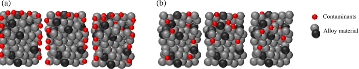
Non-evaporable getters come in the form of powdered metals or alloys, or deposited thin films of a few micrometers in thickness. In the case of powders, they are painted inside the vacuum tubes as a paste or sintered and formed into strips or other geometries. On the other hand, thin films are directly sputtered on an appropriate substrate and loaded inside the chamber [65], [66]. Since these materials are deposited ex situ a passivating oxide layer forms on the surface of the material upon exposure to air, preventing its possible reaction with residual gases within the system. The passivating layer acts as a barrier for gases to further diffuse into the bulk of the material, protecting the bulk of the material from oxidation. However, since the material is capped by a passivating layer, it must be activated once a certain level of vacuum is achieved within the chamber or device. The activation process is often achieved by annealing the material in situ, driving the surface contaminants to the bulk of the material through a diffusion process as shown in the schematic below (Figure 2.1) [21]. The diffusion process of different contaminants (e.g. C, O, N) depends on the solubility of the contaminants in the material from which the getter is composed [13]. Thus the onset of activation temperature and the degree of activation is defined by the basic constituents of the getter material, the getter morphology, as well as the crystalline nature of the getter [5], [12]. The performance of the non-evaporable getter material is also defined by a number of different variables which will be discussed below.
Alloy material Contaminants
(a) (b)
Figure 2.1: Schematic representation of the thermal activation process for non-evaporable getter alloy. (a) Shows the grains of the alloy material, with a passivating layer of contaminants encapsulating the entire surface of the material (red spheres) l. (b) Annealing the alloy to a critical activation temperature allows for surface contamination to diffuse to the bulk of the material freeing up surface sites for subsequent gettering.
2.1.2.2 Performance-limiting factors
There are multiple variables that define the performance of a getter. First, macroscopically, the sorption capacity and gettering rate can be determined by sorption measurement. A typical sorption measurement set-up is composed of two chambers, where the gas is introduced in one chamber and leaked through a small opening into the second chamber where the sample is held. The pressure difference between the chambers is measured using ion gauges. The RGA (residual gas analysis) method is often used to measure the partial pressures of constituent gases [67]. The important macroscopic parameters deduced from the sorption measurements are the pumping speed and the sorption capacity. First, the pumping speed, given by units of cm3/s, represents the volume of gas that the material is capable of absorbing in 1 second, while the sorption capacity is the total amount of gas the getter is able to absorb, and is given by units of pressure × volume. The macroscopic properties of a getter are governed by the molecular interaction between the gas molecules and the surface. Therefore, it is important to discuss the molecular-level parameters that play an important role in determining the macroscopic characteristics of a getter.
Microscopically, the material performance is dependent on the kinetics of surface-gas interaction, and bulk diffusion of trapped species [68]. The kinetics entails first the adsorption of the gas species on the surface, followed by either desorption or surface reaction, and then diffusion of the species [68], [69]. The probability of a reaction to occur between an adsorbed gas molecule and the surface, i.e. chemisorption, is dependent on the sticking coefficient and the free energy of
the molecule-surface interaction. The sticking probability is defined as the probability for an impinging gas molecule to adsorb on the surface for a finite interval of time rather than be instantaneously reflected off the surface into the gas phase [69]. The sticking probability (S) is inversely proportional to the impingement rate (v) and directly proportional to the rate of adsorption. The impingement rate is given by [69]
𝑣 = 𝑃
√2𝜋𝑚𝑘𝑇 (𝑐𝑚
−2𝑠−1) (2.1)
where P is the pressure, m is the mass of a single molecule for a given gas, k is the Boltzmann constant, and T is the temperature of the gas. The sticking probability is also dependent on the adsorbate coverage of the surface. Initially, with low surface coverage, the sticking probability is constant, but rapidly diminishes with increasing coverage values. The sticking probability varies as a function of temperature; lower temperatures are coupled with a decrease in the thermal desorption rate, and as a result higher surface coverages are achieved [69], [70].
An adsorbate can either weakly or strongly interact with a surface. Weak interaction is in the form of van der Waals forces, where a molecule can either occupy a single adsorption site or two neighboring sites depending on its orientation on the surface. On the other hand, if a molecule chemisorbs on the surface, both atoms would form strong covalent bonds on adjacent adsorption sites, and the bond between the two atoms is broken. This is assuming the diatomic molecule is symmetric in the form of X2 (X=H, O, N) [69]. CO molecules can also chemisorb on certain metal
surfaces, however, the bond between C and O is not broken, therefore CO occupies a single adsorption site [71]. Bond cleavage, which occurs during chemisorption, is dependent on the strength of the M-X bond, where M is metal surface atom, and X is the gas atom. If the M-X bond is larger than or equal to half of X-X bond, then X2 molecule would break and two M-X bonds
would form [69]. It is worth noting that the nature of H2 bonding with materials is peculiar. H2 can
be trapped molecularly or chemisorb depending on the nature of interaction between the molecule and atoms on the surface. Moreover, in non-evaporable getters, H2 molecules tend to desorb from
the material upon annealing, but are recaptured by the material when cooled down [72]. The bonding nature of the gas with the surface is dependent on the free energy, which is sensitive to the electronic structure of the surface and the availability of electrons for bonding. Chemisorption is often coupled with a negative change in enthalpy (Δ𝐻 < 0), meaning the reaction is exothermic.
As a result, the free energy of formation of the new bond is also negative (Δ𝐺 < 0). Thermodynamically, the reaction is favorable since the overall free energy of the surface is reduced. The free energy of formation is described by the Gibbs-Helmholtz relationship,
Δ𝐺 = Δ𝐻 − 𝑇Δ𝑆 (2.2)
such that Δ𝑆 is the difference between the final and initial entropy states. Since Δ𝑆 is negative after the adsorption/chemisorption of a gas molecule on a surface, due to the decrease in rotational and translational degrees of freedom, then Δ𝐻 must be negative in order to reduce the overall free energy of formation. The surface electronic structure determines whether the surface is able to covalently bond with an adsorbate or not. The outer energy bands of the material must have unpaired electrons that would participate in bonding. If the energy bands are completely filled with electrons the surface is rendered inert, as with noble metals [69]. Transition metals have partially filled d-orbitals increasing their surface activity in the presence of ambient gases [73]. Transition metals often have at least two unpaired electrons in their outer d-orbital. Since transition metals have surfaces with electronic structures that favor surface reactions, then they are ideal candidates for gas trapping and absorption.
Other variables that govern the pumping properties of a getter is the rate of gas diffusion from the surface of the material to the bulk and available surface area. Annealing at sufficiently high temperature was found to prompt surface contaminants to diffusion into the bulk [62], [74], [75]. Thus, choosing the right material (alloy) allows for optimizing the material for specific gettering applications. In the following section, a review of the different metals and metal alloys utilized for non-evaporable getter materials will be discussed.
2.1.3 Current Status of Getter
Since the initial discovery of non-evaporable getters, there has been great progress in the development of materials, as well as in the techniques used for fabricating non-evaporable getters. Table 2.1 summarizes some of the important literature that has been published since the early 1970’s until 2016, on the different materials, their preparation, and the targeted application (when listed). A large number of studies, which are not included in this list, are more focused on examining the pumping properties using sorption measurements, for different gases and at different operating temperatures. However, since the focus of this thesis is on understanding the mechanisms
of gas trapping within the getter on a molecular level, such studies were not included in this list. Looking at the range of materials used in the literature, one common denominator in the alloys developed is zirconium (Zr). Zr is a transition metal with 4 valence electrons, and an electronegativity of 1.33, therefore it has a high affinity for oxygen which diffuses readily into Zr-based oxides, nitrides, and carbides upon annealing [35], [76]. The surface properties and chemistry of Zr will be discussed in further detail in section 2.2.
There are certain requirements that must be satisfied for developing new non-evaporable getter materials for specific applications. First, an appropriate selection of the substrate is critical such that the getter thin film must exhibit good adhesion properties after deposition. Second, the activation temperature must be compatible with the targeted application, which can be tuned by changing the composition and the morphology of the thin film. Third, the constituents of the material must also have a relatively high oxygen affinity and solubility (>10%), to allow for multiple activation cycles [38]. These are general guidelines for material development for various applications, specific requirements such as high hydrogen or nitrogen capacity can be accommodated through material design and engineering [12], [14], [38], [60]. Many studies have examined the effect of thermal activation process on the surface composition of different getter alloys using surface sensitive techniques such as Auger electron spectroscopy (AES) [32], [62], [77], [78] and X-ray photoelectron spectroscopy (XPS) [34], [41], [43], [46], [79]. A few studies have also utilized secondary ion mass spectroscopy (SIMS), elastic recoil detection (ERD), X-ray diffraction (XRD), and other bulk techniques to characterize the change in bulk composition of the material (ERD, SIMS), and in crystalline phases of materials (XRD) as a function of temperature and reactivity with different gases [80]–[85].
2.1.3.1 Non-Evaporable Getter: Deposition & Influence on Morphology
As shown in Table 2.1, the preparation of getter material can be achieved by either ball-milling, e-beam evaporation, or magnetron sputtering, depending on the application. For more recent non-evaporable getters (NEG), magnetron sputtering is usually the more favored technique, since it allows for alloying of materials easily, as well as the control over the structure and composition of the deposited thin film by optimizing deposition parameters. In magnetron sputtering, substrate temperature, deposition pressure, substrate material and structure, and flow of sputtering gas have a significant impact on the microstructure of the deposited thin film, which influence the gettering
properties of the thin film. Benvenuti, et al. [86] studied the effect of substrate temperature on the microstructure of a Ti-Zr-V thin film. Ti-Zr-V thin films were deposited for particle accelerator applications, where the getter must be activated at temperatures lower than 200oC for aluminum-based chambers. In their study, they varied the substrate temperature from 100 to 350oC, and found that 250oC was the optimal temperature for achieving highly porous thin films. The porosity of the thin film is coupled with the presence of columnar structures in the cross-section of the thin film, which act as channels for the diffusion of contaminant species from the surface to the bulk of the material. The activation temperature of the thin film deposited at a substrate temperature of 250oC was found to be 180oC, compatible with aluminum chambers for particle accelerators [86]. Malyshev, et al. [87] showed that higher sputtering pressure increases the roughness of the thin film and introduces a larger distribution of columnar structure for Ti-Zr-V thin films. Other studies investigated the effect of glancing angle between substrate surface and target on morphology of Ti-Zr-V [88], pressure and substrate temperature on morphology and sorption properties of Zr-Co-Ce getters [89]. This is as far as getter morphology and thin film composition, as mentioned in the previous section, influence the activation temperature and efficiency of contaminant bulk diffusion.
Table 2.1: List of non-evaporable getter materials examined in the literature, the deposition technique, their activation temperature, and the targeted application.
Material Deposition Technique Activation Temperature Application Reference Ti capped with Au
Magnetron sputtered 380-415oC MEMS [90] Ti capped
with Ni, Au
e-beam evaporation 300oC MEMS [91]
Ti capped with Cr, Pt
e-beam evaporation 200-400oC N.A. [92]
TiZrV Magnetron sputtered <300oC Particle
accelerators [32], [77], [81], [83], [85], [88], [93]–[100] TiHf, TiZr, TiZrV, HfZr
Magnetron sputtered <400oC Particle
accelerators
[33] Ti-Mo Sintered powders or
magnetron sputtered 400-750oC N.A. [101], [102] Zr(VxFe1-x)2 ZrMn2, TiFe Radio frequency melting <430oC N.A. [43]
Zr, Ti, Mn
ZrVFe Powder <600oC N.A. [80]
Zr(VFe)2 Powder N.A. N.A. [103]
Zr2Fe Powder N.A. N.A. [104]
Zr2Fe, ZrVFe Arc melted ingot 400-800oC N.A. [45], [57], [105]
ZrV Magnetron sputtered <320oC Particle accelerators
[39], [41], [106], [107]
ZrV, ZrCo, ZrTi
Magnetron sputtered <350oC N.A. [108]
ZrAl, ZrNi, ZrVFe
N.A. <800oC N.A. [34]
ZrCo with Ni cap
Arc melted H2 storage [109]
ZrCoCe ZrCoREM
Magnetron sputtered <330oC MEMS [30], [47], [89], [110]
ZrCoREM Powder <330oC N.A. [111]
ZrFe Arc melted 500oC N.A. [78]
ZrFeV with Pd cap
Arc melted 550oC H2 storage [112]
ZrTiV Electromagnetic induction melting
260oC H2 storage [44]
ZrVFe Magnetron sputtered <700 Accelerator [46], [72], [79], [113], [114]
Rf melted <380 MEMS [115]
Zr-Zr(VFe)2 Powder N.A. N.A. [116]
2.1.3.2 NEG Alloying Effects
Mašek, et al. [41] investigated the effect of varying Zr-V alloy composition on the activation temperature of the getter. They used intertwined wires as the target material for magnetron sputtering, and by changing the number of wires used of each metal, the film composition was
altered. During the in situ activation process which was monitored using XPS, it was shown that higher V content led to a lower activation temperature (220oC). The activation process is often
monitored by tracking the level of oxygen and oxygen-related species on the surface of the material [34]. Mašek, et al. found that VxOy tends to be the first species to be reduced to metallic state, and
more efficiently than ZrO2, by heating the samples to 220oC for 2 hours under ultra-high vacuum
(UHV). By varying the V content (34%, 54%, and 72%), they found that very high V content is coupled with a decrease in the rate of the activation process, and the optimal composition was found to be 54% V. However, despite increasing the temperature to 320oC, the surface still contained sub-oxide species. The thermal treatment also showed that Zr is more actively reacting with other constituents of the passivation layer, such as H2O and hydrocarbons, where carbide and
hydroxide species are formed upon annealing. On the other hand, V only seemed to be reactive with O2 [41]. From their study, it appears that Zr has a higher affinity to contaminants compared
to V, which leads to the slower activation process of Zr compared to that of V. The authors did not investigate or discuss the underlying causes of different behavior of V and Zr in the thin film, however one can deduce the following based on their observations. When V content was increased to 72%, the activation process was found to significantly decrease, i.e. higher O content was retained on the surface, which indicates that a sufficient amount of Zr in the matrix facilitates the reduction process. Moreover, Zr and V have an electronegativity of 1.33 and 1.63, respectively, indicating that Zr has a higher affinity to O, which assists in the diffusion process of O to the bulk of the material [76]. The enthalpy change for the oxide and carbide formation for Zr is more negative than V. Consequently, it is more thermodynamically favorable for Zr than for V to stay in the oxide state during the activation process [34]. Thus, by achieving a balance between the two elements, one can attain a low activation temperature getter.
Similar behavior was observed in TiFe alloys, where Fe was completely reduced to metallic phase at 357oC while Ti remained oxidized [43]. Meli, et al. [43] compared the behavior of TiFe alloy upon annealing to 357oC to that of pure Ti, and found that in pure Ti, the metallic phase is fully recovered after subjecting Ti to the same annealing conditions. These observations indicate that during the annealing process, both Ti and Fe oxide phases are decomposed, but the oxygen from Fe can be recaptured by Ti, due to the difference in electronegativity (Ti: 1.54, Fe: 1.83) resulting in the fast and complete reduction of FexOy to Fe0 assisted by Ti oxidation [43], [76].
and carbide for Ti is significantly lower than that of Fe [34]. Thus, alloying has a significant effect on the activation temperature and the pumping properties of a getter material. Alloying increases the number of defects and grain boundaries in the material, which can significantly reduce the activation temperature and increase the surface area. By varying the alloy composition and optimizing the deposition process, nanocrystalline grains with sizes that range between 3-5 nm can be formed increasing the number of grain boundaries and therefore facilitating the diffusion of the passivation layer to the bulk [32].
Analytical models based on Fick’s law have been developed to describe the gettering mechanisms, however the studies targeted dense polycrystalline rather than porous materials [52], [68]. Therefore, there is a still gap in the fundamental understanding of the trapping and diffusion of contaminant species in porous materials. A quantitative and predictive models would take into account microstructural contribution to the activation and gettering properties of various materials. Where diffusion through the material is governed by Fick’s law only through the grains, in contrast the diffusion through the pores would be considered more surface diffusion.
2.1.3.3 Recent NEG Material
The more recently developed getter materials for MEMS applications is a Zr-Co-rare earth metals (REM) alloy, with a relatively low activation temperature at 300oC, compatible with the
temperature-sensitive nature of MEMS devices [47], [110]. The material is nanoporous and composed of nanocrystalline grains that substantially increase its surface area. Xu, et al. [89] investigated the effects of magnetron sputter deposition pressure and substrate temperature on the microstructure and hydrogen sorption properties of a Zr-Co-Ce thin film. The target material is an alloy of 76.2:20.7:3.1 (atomic%) of Zr:Co:Ce. The deposition pressure and Si substrate temperature were varied from 1-60 mTorr and 25-300oC, respectively. Their results show that lower deposition pressures produced denser thin films with poor getter characteristics. In contrast, high sorption properties were obtained at substrate temperature of 150oC coupled with a high specific surface area as measured by Brunauer–Emmett–Teller (BET) [89]. The sputter deposition parameters affect the mobility of adatoms on the surface of the substrate, and the microstructure can be predicted using the structure zone model [117]. In a separate study, Xu, et al. [30] examined the effects of activation temperature on the microstructure of a Zr-Co-Ce getter, as well as the stability of the material to different cleaning processes. They investigated the material’s thermal behavior
in the range of 250-400oC. They concluded that high sorption capacity is achieved with an
annealing cycle at 300oC for 30 minutes. Scanning electron microscopy (SEM) analysis
demonstrated a slight change in the microstructure of the thin film as a function of temperature. They observed a growth in the nanocrystalline grains with increasing temperature and increase in the crystallization, however they did not provide detailed analysis regarding the nature of the evolving nanocrystals [30].
As shown in the previous sections, Zr is the most common component of NEGs, thus reviewing the structure, chemistry, and reactivity of pure Zr with gases is an important step in understanding the mechanisms of gas trapping within NEGs.
2.2 Zr: Chemistry, Reactivity, & Applications
Zr has a wide range of industrial applications. One of the earliest uses for Zr is in the nuclear reactor industry, due to its low neutron absorption [37], [118], [119]. Moreover, because of Zr’s high chemical reactivity with gases, it is one of the most used metals in the development of non-evaporable getters. Zr alloys have been utilized for a number of applications; ZrCo alloy for tritium storage and handling [120], variety of Zr-alloys for getter applications (as shown in Table 2.1), zirconia for dental application [121], [122], and ZrN and ZrC for machining and cutting tools [123]. Zr is an abundant metal representing 0.017% of the lithosphere, similar to carbon concentration [37]. Due to its highly reactive nature, it is not present as a pure metal, but rather as an oxide, ZrO2.
High purity Zr has two phases, α-Zr (HCP) and β-Zr (BCC) stable below and above 860oC, respectively. Pure Zr can only be prepared under vacuum or inert conditions, especially in the absence of oxygen, nitrogen, hydrogen, and carbon, which are readily absorbed by Zr. In order to obtain a pure metal, a reducing agent must be added to reduce ZrO2 to metallic form. Reducing
agents can be in the form of Mg, Al, or Ca, which have higher O affinities than that of Zr. Zr is able to dissolve up to 29 atomic % and 20 atomic % of oxygen and nitrogen, respectively, in its lattice at increased temperatures, without the separation of a ZrO2 phase. On the other hand, ZrC
phase forms and separates readily after the incorporation of 1 atomic% of carbon [37]. Zr surface reactivity arises from the fact that the metal has two unpaired electrons in its outer 4d-orbital, and has four valence electrons. Its atomic mass is 40 and thus its electron configuration is [Kr] 4d2 5s2 [37]. Moreover, Zr one of the more electropositive transition metals, with an electronegativity of
1.33, thus not only it reacts with surrounding oxygen, it can also reduce other metal oxides granted the metals are more electronegative than Zr [37], [76].
When the metal is purified and exposed to ambient atmosphere, a passivation layer of oxide forms on the surface, which prevents the bulk of the material of interacting with other gases. Therefore, the oxide layer forms as both a diffusion barrier and as a corrosion-resistive layer [118]. When the metal is subjected to annealing at 250oC, it is found to slowly react with surrounding hydrogen. Heating Zr under UHV up to 500oC, allows for the passivation layer constituents to diffuse to the bulk of material rendering the surface of the metal active to interact with surrounding gases. In terms of hydrogen, Zr can rapidly solubilize a hydrogen molecule at 150oC as an interstitial hydride compound. Absorbed hydrogen shows a hysteresis phenomenon, where hydrogen can be reversibly absorbed and desorbed depending on the temperature at which the metal is annealed [37], [118], [124]. Hydrogen absorption results in the embrittlement of the metal, however, hydrogen can be expelled from the material by annealing the metal under vacuum at high temperatures [37]. It can also readily react and diffuse oxygen, carbon, nitrogen, and other oxygen-containing gases [35], [37], [125], [126]. Rate of nitrogen diffusion in Zr is lower than that of oxygen, but increases with increasing temperatures, especially beyond the α – β phase transition [37]. Zr’s reactivity with different gases has been extensively investigated using surface sensitive techniques such as in situ AES and XPS. Many studies have been conducted on its reactivity with oxygen [35], [125]–[132], hydrogen [130], [131], [133]–[135], deuterium [35], carbon monoxide [35], [125], [126], hydrocarbons [136], [137], and nitrogen [35], [125], [126], [138], [139].
CHAPTER 3
EXPERIMENTAL TECHNIQUES
As discussed in the previous chapter, gettering reactions occur on the surface of the material and therefore it is important to examine the surface chemistry and how it evolves during the thermal activation process as well as in the presence of contaminating gases. The most common technique for analyzing surfaces for chemical composition and bonding is X-ray Photoelectron Spectroscopy (XPS). One important characteristic of certain XPS systems is in situ annealing capabilities, which allows for monitoring the evolution of surface composition during the thermal activation process of non-evaporable getters. It is also important to characterize the distribution of the contaminants within the bulk of the material through depth-resolved analysis. Time of Flight Secondary Ion Mass Spectrometry and Time of Flight Elastic Recoil Detection are qualitative and quantitative material science techniques that are used for in-depth analysis of chemical composition. This chapter will briefly discuss the theory on which these techniques are based.
3.1 X-ray Photoelectron Spectroscopy
3.1.1 Overview
The photoelectric effect was discovered by Hertz in 1887 during his attempts to experimentally validate Maxwell’s equations. Many studies followed Hertz’s observations in attempt to explain the phenomenon. However, it was not until 1905 that Einstein explained that high energy, low intensity electromagnetic radiation would induce electron emission from metal surfaces. Einstein described the energy of a photon using Planck’s constant and the frequency of the photon for which he won the Nobel Prize in 1921. After the discovery and experimental confirmation of the phenomenon, scientists attempted to exploit the photoelectric effect for spectroscopic methods. Nevertheless, the lack of high vacuum systems and electronics to support it rendered the development of spectroscopic techniques difficult. It wasn’t until 1950’s that a spectroscopic technique was developed to detect photoelectrons by Kai Siegbahn in Sweden. The first ESCA (electron spectroscopy for chemical analysis) spectrum was produced in 1955. Siegbahn was awarded a Nobel Prize in physics in 1981 for his development of the ESCA technique [140]–[144].
3.1.2 Set up & Theoretical background
ESCA, or what is known today as X-ray photoelectron spectroscopy (XPS), is a surface analysis technique that provides information about the chemical composition and bonding nature of atoms of surfaces. A conventional XPS set up is displayed in a schematic in Figure 3.1. It consists of an X-ray source, a concentric hemispherical electron analyzer, and a detector. Samples are irradiated with soft X-rays of energies 1.2-1.5 keV, which results in the emission of core-level photoelectrons with kinetic energy KE. The emitted photoelectrons are focused and directed to an electron analyzer by means of electrostatic lenses and are deflected according to their kinetic energy [145]. KE of the photoelectron is dependent on the energy of the incident X-ray photon (hv), the binding energy of the photoelectron (BE), and the work function of the spectrometer (ϕ). KE is given by the following equation,
𝐾𝐸 = ℎ𝑣 − 𝐵𝐸 − 𝜙 (3.1)
Where h is Planck’s constant and v is the frequency of the impinging photons. The binding energy is given by the energy difference of the material’s Fermi level (EF) and the core energy level from
which the photoelectron was ejected (Figure 3.1). All elements of the periodic table can be detected using this technique, except for hydrogen and helium. Hydrogen cannot be detected because the hydrogen atom has a single valence electron and an extremely small photoionization cross-section. Therefore, if hydrogen is present in the material and it is ionized due to absorption of high energy X-rays, then the hydrogen signal would overlap with valence electrons ejected from other atoms within the material at very low binding energy (<20 eV) [146]. The KE given by the equation above assumes that the photoelectron emission process is elastic. If the photoelectron suffers energy loss (i.e. inelastic emission) this would give rise to a stepped background as marked in Figure 3.2. Conventional XPS uses either Al Kα, Mg Kα, or Zr Mζ with photon energies of 1486.3 eV, 1253.6 eV, and 151.4 eV respectively [142], [145]. X-rays of this energy can penetrate a few micrometers in depth of a solid, however the probed depth by XPS is typically on the order of a few nanometers. The surface sensitivity of XPS rises from the fact that photoelectrons have an inelastic mean free path (IMFP) on the order of 0.3-5 nm [147]. Therefore, photoelectrons that are emitted from deep within the material (i.e. beyond 10 nm) experience inelastic collisions with atoms or other electrons that dissipate their KE. Due to the electron’s small IMFP, XPS measurements must be carried out under ultra-high vacuum in pressures below 10-9 Torr, to minimize energy loss of photoelectrons
with gas molecules. The XPS probing depth therefore depends on the IMFP, such that 95% of the signal comes from a depth equivalent to 3λi, where λi is IMFP of the photoelectron. The probing
depth, also referred to as escape depth, is given by the following equation
𝑑 = 3𝜆𝑖cos 𝜃 (3.2)
where d is the probing depth and θ is the photoelectron take-off angle with respect to the surface normal [145]. By changing the take-off angle, the sampling depth can be varied, and information regarding uppermost monolayers can be deduced. However, the sample surface must have minimal roughness, since roughness and grains lead to shadowing effects [145]. Today, the attenuation length of photoelectrons through a material is used as a more comprehensive parameter instead of the IMFP. The attenuation length is defined as the transparency of a solid material to an electron, i.e. how far an electron can travel through a specific solid material experiencing minimal energy losses. One must distinguish IMFP from the attenuation length of electrons, such that the former is defined as the average distance between inelastic collisions [144], [148]. Recently, a more comprehensive parameter has been introduced, known as the effective attenuation length, which takes into account both elastic and inelastic collisions [144].
Figure 3.1: (Left) Energy band diagram representation of the photoelectric emission process. A core level electron absorbs a photon of energy hv, resulting in the emission of the photoelectron with kinetic energy KE. (adapted from [142]) (Right) Schematic representation of a conventional XPS set up, presenting the X-ray source, the sample, electron analyzer and the detector. (reproduced from [151]).
Attenuation lengths are approximated both theoretically and experimentally using over-layer experiments. Approximations are made regarding the over-over-layer, such that the surface is considered to have minimal roughness. Therefore, the estimated values prior to the development
EF K BE hv Lens Detector Sample e -hv
of accurate techniques to measure thin film thickness and roughness such as atomic force microscopy generally have large errors (50% or more) [148]. The effective attenuation length, λAL,
is approximated using the following equation,
𝜆𝐴𝐿 = 𝜆𝑖(1 − 0.028√𝑍)(0.501 + 0.068 ln(𝐾𝐸)) (3.3) where Z is the atomic number, and KE is the kinetic energy of the electron [144]. A comprehensive database of the electron effective attenuation length is given by NIST, the National Institute of Standards and Technology [149]. In a specific system where there is an over-layer involved, the theoretical approximations would not be representative of the actual attenuation length of the photoelectrons. Experimentally, from XPS intensity variation, the signal intensities must be taken into account according to the following equation,
𝐼 𝐼∞ = 1 − exp (− 𝑡 𝜆𝑖cos 𝜃) (3.4) 𝐼𝑠 𝐼𝑠0 = exp (− 𝑡 𝜆𝑖𝑠cos 𝜃) (3.5)
Such that 𝐼 𝐼⁄ ∞ is the ratio of the intensities from the layer to the intensity of a thick
over-layer, while 𝐼𝑠 𝐼𝑠0
⁄ is the ratio of intensities for the signal from the covered substrate to the bare substrate, and 𝜆𝑖, and 𝜆𝑖𝑠 are the IMFP of the photoelectrons from the over-layer and the substrate, respectively [148]. The two equations above depend on prior knowledge of the over-layer thickness (t). Thus, a more practical approach to approximating the effective attenuation length (λAL) was developed in 1997 by Cumpson and Seah [150] which takes into account material
properties. The effective attenuation length developed by Cumpson and Seah is given by,
𝜆𝐴𝐿(𝑛𝑚) = 0.31 [109( 𝑀 𝜌𝑛𝑀𝑁𝐴) 1 3⁄ ] 3 2⁄ [ 𝐾𝐸 𝑍0.45(ln(𝐾𝐸 27⁄ ) + 3)+ 4] (3.6)
The first half of the equation takes into account properties of the material such as molar mass M (kg/kmol), density ρ (kg/m3), nM number of atoms in a molecule, and Avogadro’s number (NA in
atom with mass Z [144], [150]. A detailed discussion on the more recent progress in estimating the attenuation length is given by Jablonski and Powell [148], [149]. Therefore, in order to have a better approximation of the probing depth, instead of using the IMFP in equation (3.2), it is substituted by λAL from equation (3.6).
3.1.3 Spectral shape & Quantification
XPS spectra are plotted as intensity, number of counts of photoelectrons per second, as a function of BE. Sharp peaks emerge at specific electron binding energies that are signatures for their respective atomic species, thus XPS gives information regarding the chemical composition of the surface [151]. The BE of a photoelectron represents the Coulombic attraction of the electron to the nucleus, which can be screened by the interaction of other electrons with the nucleus within the atom. Therefore, any type of chemical bonding (covalent, ionic) or van der Waals interaction between the atom and its surroundings results in the deformation of the electron density, thus changing the BE of the photoelectron [151]. As a result, XPS can provides information not only on the chemical composition of the surface, but also the nature of bonding between atoms.
1200 1000 800 600 400 200 0 0 40000 80000 120000 160000 In tensity (Cou nt s/s)
Binding Energy (eV)
O Auger
Zr4s O1s
Zr3p Zr3d
C1s


![Figure 3.4: Schematic representations of (a) TOF-SIMS (adapted from [156]) and (b) TOF-ERD (adapted from [159])](https://thumb-eu.123doks.com/thumbv2/123doknet/2322239.29336/42.918.109.774.438.727/figure-schematic-representations-tof-sims-adapted-tof-adapted.webp)