HAL Id: hal-01701682
https://hal.archives-ouvertes.fr/hal-01701682
Submitted on 4 Dec 2019HAL is a multi-disciplinary open access archive for the deposit and dissemination of sci-entific research documents, whether they are pub-lished or not. The documents may come from teaching and research institutions in France or abroad, or from public or private research centers.
L’archive ouverte pluridisciplinaire HAL, est destinée au dépôt et à la diffusion de documents scientifiques de niveau recherche, publiés ou non, émanant des établissements d’enseignement et de recherche français ou étrangers, des laboratoires publics ou privés.
Determination of precipitate strength in aluminium
alloy 6056-T6 from transmission electron microscopy in
situ straining data
Marie Vivas, Philippe Lours, Christophe Levaillant, Alain Couret, Marie-José
Casanove, Armand Coujou
To cite this version:
Marie Vivas, Philippe Lours, Christophe Levaillant, Alain Couret, Marie-José Casanove, et al.. De-termination of precipitate strength in aluminium alloy 6056-T6 from transmission electron microscopy in situ straining data. Philosophical Magazine a, Informa UK (Taylor & Francis), 1997, 76 (5), pp.921-931. �10.1080/01418619708200007�. �hal-01701682�
Determination of precipitate strength in aluminium alloy
6056-T6 from transmission electron microscopy in
situ
straining data
By MARIE VIVAS, PHILIPPE LOURS, CHRISTOPHE LEVAILLANT Centre Matkriaux, Ecole des Mines d’Albi-Carmaux, Campus Jarlard,
81013 Albi Cedex 09, France
ALAIN COURET, MARIE-JOSE CASANOVE and ARMAND COUJOU Centre d’Elaboration des Materiaux et #Etudes Structurales,
29 Rue Jeanne Maruig, BP 4347, 3 I055 Toulouse Cedex, France
ABSTRACT
The transmission electron microscopy in-situ straining technique is employed to measure the breaking angles of strengthening precipitates in aluminium alloy 6056-T6 as they are sheared by dislocations. The experimental determination of
the character of bowed dislocation segments when dislocations are pinned on
precipitates allows us to calculate the corresponding line tensions. From this, the maximum forces Fm that precipitates can sustain before being sheared by dislocations are deduced. It is suggested that F, may be regarded as a quantitative parameter which includes the effects of the various strengthening mechanisms operative in precipitation-hardened alloys. An attempt is made to
relate the maximum force calculated from in-situ straining data to the
macroscopic yield strength of the material.
5
1. INTRODUCTIONIn precipitation-hardened aluminium alloys, for instance those of the 6XXX
series, strengthening is provided by the interaction of dislocations with fine pre- cipitates. The alloys are solution heat treated above the solvus temperature, quenched and tempered. As the alloy is tempered, alloying elements in excess in the supersaturated solid solution give rise to the nucleation and growth of precipi- tates acting as obstacles to dislocation glide. For T6 peak-aged alloys with composi- tion close to that of aluminium alloy 6056, the presence of needle-shaped
p”
and lath-shaped L precipitates have been reported (Sagalowicz et al. 1994). In the systemAl-Mg-Si with or without copper additions, various types of precipitate (rod, needle or lath shaped) were observed, depending on the content of alloying elements and the temperature and duration of tempering (Jacobs 1972, Lynch et al. 1982, Matsuda et al. 1994,1996, Edwards et al. 1994,1996, Donnadieu and Proult 1996). However, the
precise morphologies, chemical compositions and crystal structures of precipitates are still subject to controversy.
Strengthening models for such alloys include parameters such as the volume fraction of precipitates, the distribution of precipitates in the slip planes of disloca- tions and the maximum forces that precipitates can sustain before being sheared by dislocations (Brown and Ham 1971, Gerold 1979). The determination of this force,
Fig. 1
Configuration of a dislocation pinned on a precipitate: parameters of the constant-line-tension model.
which is a characteristic of the material, requires the measurement of the breaking angle
&
corresponding to the critical position at which the obstacles break and the dislocations advance to new particles (fig. 1). For instance, according to the con- stant-line tension model which assumes that the line tension T is a constant whatever the dislocation character (Guyot 1979), the modulus ofF,
is given byIn fact, the line tension of a dislocation strongly depends on its character (DeWitt and Koehler 1959). This must be taken into account for the determination of Fm which has to be calculated using the so-called orientation-dependent line tension model.
Standard transmission electron microscopy (TEM) post-mortem observations of dislocations pinned on precipitates in free-stress specimens do not allow one to determine the critical breaking angles. The specificity and benefits of the TEM in-situ straining technique employed here are that experiments are carried out under a load and, as a Consequence, dislocations can be imaged in a critical position just before they shear the precipitates. From the experimental measurement of the break- ing angles, it is possible to calculate the values of F,. The results presented here are obtained at room temperature; the role of the temperature as well as the influence of F, on the mechanical properties of the material will be discussed in a further paper (Vivas et al. 1997). The TEM in-situ straining technique has been described elsewhere in detail (Coujou et al. 1990, Couret et al. 1993). Nevertheless, note that two aspects, inherent to the material investigated, make observations difficult: firstly specimens are polycrystals which forbids any prediction on the active slip systems, and secondly dislocations and precipitates cannot be adequately imaged simultaneously (the best compromise being obtained with the diffraction vector (220)). However, the mean distance between precipitates in the slip planes of dislocations is much lower than the foil thickness, which guarantees that no imaging artefact occurs.
Q 2. EXPERIMENTAL DETAILS
The table gives the chemical composition of aluminium alloy 6056. The alloy is solution treated at 550°C and quenched and tempered at 175°C for 8 h (T6 temper). Material is delivered in the shape of rolled sheets 1 6 m m thick. TEM specimens are cut using the spark erosion technique, mechanically ground and jet electro- polished. Figure 2 (a) is a
[OOl]
zone-axis bright-field image showing the microstruc- ture of alloy 6056-T6 prior to straining. The micrograph shows the cross-sections ofChemical composition of aluminium alloy 6056.
Element A1 Si Mg Cu Mn Fe Zn Zr Cr Ti
Amount (wt%) Balance 0.943 0.869 0.798 0.634 0.198 0.153 0.11 0.066 0.039
the precipitates intercepting the (001) plane. Seen on the micrograph are two types of precipitate: needle-shaped particles with a roughly circular cross-section and lath- shaped particles with a transverse cross-section close to a rectangle, referred to as N, and N2 and as L1 and L2 respectively. Some laths, that is L3 and L4 are imaged along their longitudinal cross-section which allows us to measure the length of those par- ticles ranging from 15 to 165nm. Note that the distribution of precipitates is quite homogeneous and that particles lie preferentially along the (100) directions of the aluminium matrix. The high-resolution transmission electron micrograph in fig. 2 (h)
Microstructure of alloy 6056 T6: (a) [OOI] zone-axis bright-field image; (b) high-resolution TEM image of needle-shaped precipitates viewed edge on; (c) high-resolution TEM image of lath-shaped precipitate viewed edge on.
shows needle-shaped precipitates viewed edge on. The roughly circular cross-sections have diameters of about 2 4 nm. Figure 2 (c) shows a lath-shaped precipitate viewed edge on. The cross-section of the precipitate is close to a rectangle with dimensions 9 nm and 3 nm. Compared with the aluminium matrix where the atomic columns are easily imaged in high-resolution transmission electron micrographs, the precipitates usually display complex patterns. These patterns can be attributed either to a dis- ordered structure, or more probably to the presence in the particle of an atomic distance too small to be resolved by the microscope. Work is in progress to deter- mine the structure of the precipitates and to establish the orientation relationship between the precipitates and the matrix.
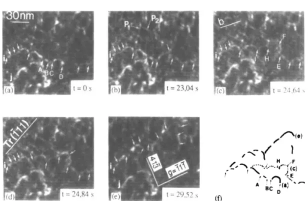
Figure 3 displays a deformation sequence issued from an in-situ straining experi- ment performed at room temperature. Images, taken from the video tape recording, are viewed in dark-field condition (g =
[I
1 llA1). This straining sequence shows an example of a dislocation passing through an array of precipitates. As no dislocation loops were observed when the alloy is strained, it is concluded that the prevalent deformation mechanism is pure shearing. Precipitates PI and P2 and dislocation j are used as reference features as they remain immobile during the whole sequence.The micrograph in fig. 3 (a), corresponding to the initial stage of the deforma- tion, shows the dislocation i with Burgers vector b = (a/2)[101] pinned on obstacles
indicated with arrows. Under the effect of the applied stress, the dislocation bows in between the particles. Note that the contrast of the dislocation vanishes in the vicinity of the precipitates, for instance in A, B and C in fig. 3(a). This results from a compensatory effect of strain fields associated with the dislocation and with the particles in the image contrast and is used to determine the position of
Fig. 3
Dynamic TEM in-situ straining sequence showing the shearing of precipitates by a dislocation:
(a)-(e) five successive steps of deformation; (f) recapitulative sketch of the whole sequence.
the precipitates. From fig. 3 (a) and (b), the increase in the applied stress increases the bending of the dislocation segment which unpins from D. From fig. 3(b) and (c), dislocation i shears the precipitates A, B and C and then moves in the
(11
1) plane to another series of obstacles E, F, H and I. From fig. 3(c) to (a), note again the increase in dislocation bending between obstacles F and H due to the action of the applied stress. From fig. 3(4 to (e), dislocation i shears precipitates E, F, H and I and advances to new obstacles indicated with arrows in fig. 3 (e). The overall motion of the dislocation is detailed in the sketch in fig. 3cf)
where the three locked positions of the dislocation are indicated. They correspond to the straining states of fig. 3(a), (c) and (e).This video tape recording clearly shows that the microscopic mechanism which controls the deformation of the material is the shearing of precipitates by disloca- tions. Each precipitate gives rise to a force on the dislocation. Bending of the dis- location segments is provoked by the pinning of dislocations on precipitates due to this interaction force and to the action of the applied stress. Note that, for other orientations, this mechanism, although predominant, may be accompanied by the formation of dislocation loops induced by cross-slip as well as a few Orowan loops (Vivas et al. 1996). The next section details the measurement and calculation of the force associated with this shearing deformation.
4
3. PRECIPITATE STRENGTHThe interaction force between precipitates and dislocations may originate from several effects such as chemical, modulus, coherency strain or atomic order strength- ening. Depending on the type of interaction and on the size of the hardening par- ticles, there will be a critical force (or maximum force F,) at which the obstacles break and the dislocations advance to new obstacles.
The principle of calculation of the critical force is displayed in fig. 4 (a) showing the interaction between a dislocation with orientation-dependent line tension and a precipitate with finite dimensions. The precipitate cross-section in { 11 1) plane is assumed to be roughly elliptic. The dislocation is in contact with the precipitate
Fig. 4
Principle of calculation of the critical force; parameters of the orientation dependent line tension model: 4(a) configuration of a dislocation pinned on a precipitate with finite dimensions, 4(h) the resultant vector F,.
between points A and B. The force exerted by the dislocation on the precipitate is the resultant of the line tensions T1 and T2 which are tangent vectors to the dislocation line at A and B. The resultant vector, displayed in fig. 4(b), goes through I, the converging point of T1 and T2.
p1
and ,02 are the angles between the Burgers vector of the dislocation and TI and T2 respectively. The real situation analysed is that of fig. 5 which is an enlarged detail of fig. 3(d)
showing the dislocation in the critical position just before it shears the precipitate. As indicated, dislocation contrast is small as dislocation is in contact with the precipitate between A and B. The projections in the observation plane of the line tensions TI, and TZp and the Burgers vector b, are given in the figure. From this micrograph, the apparent angles between the projected Burgers vector b, and the projected line tensions T1, and T2p are measured. Values are then corrected by taking into account both the specimen tilt angle and the inclination of the slip plane with respect to the foil plane to give the true values of angles. From those values, which define the character of dislocation segments, the maximum force F, sustained by precipitates prior to shearing are derived. For simplicity and because of the characteristics of aluminium, elastic isotropy has been assumed in order to calculate the line tensions. This was performed in the framework of the free-line-tension model which takes into account the dependence of the line tension on the dislocation character using the DeWitt-Koehler formulawhere E ( P ) is the line energy of dislocation per unit length:
where p (= 29.3 GPa) is the shear modulus, b ( = 0.286 nm) is the Burgers vector of
the dislocation, v (= 0.347) is Poisson's ratio, ,6 is the angle between the dislocation line and the Burgers vector, and L and I are the outer cut-off distance and inner cut-
off radius respectively of the elastic strain field of the dislocation.
For precipitation-hardened alloys, the line tension may be affected, via the logarithmic term in eqn. (3), by the values of the inter-particle distance and the width of the particle cross-section intersecting the slip plane. Indeed, for large breaking angles, the outer cut-off distance L may be of the order of the interparticle distance whereas, for breaking angles close to zero, L may be of the order of the particle width (Ashby 1968). As in most experiments, the measured breaking angles were greater than 30°, L was taken to be equal to 20 nm, the mean interparticle distance, in our calculations. The vector F, is expressed as the opposite to the resultant
T1
+
T2 and its modulus isF, =
[Tf
+
T;+
2Tl T2 cos (p2 - p1)]1'2. (4)For the case displayed in fig. 5, for which
p1
= 126" andp2
= 46", one has TI M 0.36 nN, T2 M 0.44 nN and F, M 0.61 nN.Two causes of uncertainty may affect the values of F,. The first is due to the determination of angles
p,
directly related to the position chosen for vectors T in the TEM in-situ images. This is estimated to be A,O = f5", leading to an average un-certainty AF, = f0-05 nN. This was introduced in the width of the histogram bars in fig. 6. The second is relative to the values of the inner and outer cut-off distances
Fig. 5
Image of a dislocation in critical position for shearing a precipitate (bp is the projected Burgers vector of the dislocation, TI, and TlP are the projected line tensions of the dislocation
segments).
used in the calculation. It is generally assumed that r is of the order of b but the value of L is somewhat more difficult to assess. Nevertheless, we verified that an uncer- tainty f 10 nm in L leads to an uncertainty in F, of about 10.07 nN. The overall uncertainty due to both effects is of the order of 10.12 nN. However, the two causes of error are very different. The first is directly related to the technique of measure- ment whereas the second is relative to dislocation theory. In order to compare various precipitation-hardened alloys, only the uncertainty in the measurement is relevant provided that L and r are identical in all calculations. Note that the attrac- tion of dislocation segments, reducing the line energy, has been neglected. In the case of very small breaking angles, it can be significant which might lead to slightly overestimated values of F,. For statistical purposes, F, was evaluated for some 20 distinct dislocation-precipitate shearing interactions. Results are reported in the histogram in fig. 6 where, as indicated above, the width of the histogram bars was
Fig. 6
taken as the mean absolute uncertainty in the measurement of F,. The nearly Gaussian distribution of forces ranges from about 0.35 to 1.25 nN, with an average value close to 0.6 nN.
8
4. DISCUSSIONPrior to discussing the relevance of measuring precipitate strength to address the hardening mechanisms of alloy 6056-T6, as well as the limitations of the method- ology, it is necessary to emphasize on the physical reasons for the scatter of the experimental values of forces F,,,.
This scatter originates in the variety of shapes and sizes of precipitates en- countered by the dislocations in their slip planes. Needle-shaped and lath-shaped precipitates with rounded angles intercept the { 11 l } planes respectively as ellipses (fig. 7 (u)) and rounded-edge rectangles (fig. 7 (b)).
For a given size of precipitates (needle or lath), two types of interaction must be considered: either the dislocation hits the precipitate towards its smallest side (figs. 7 ( c ) and (e)) or towards its largest side (figs. 7 ( 4 and (f)). In the first case, shearing of the particle is assumed to be easier than in the second case. For a needle- shaped precipitate for instance, the pertinent parameter to describe the interaction is the force F exerted by the dislocation per unit length dl of precipitate:
This force, proportional both to the reciprocal radius
R
of curvature of the particle and to the line tension T of the dislocation, is five times larger in the case in fig. 7 (c) than in the case in fig. 7 ( 4 . In fact, when the dislocation starts to shear the pre- cipitate, the relevant geometrical parameter to take into account is the effective width of precipitate that is being sheared. As a consequence, precipitate shearing according to the mechanism displayed in fig. 7 (d) must not be operative as it requires a much higher stress than that displayed in fig. 7 (c). The additional mechanism, detailed in fig. 7 (c) as well, where the dislocation shears the precipitate along the minor axis of the ellipse even though it meets the precipitate towards the major axis may be proposed. In the case of a lath-shaped precipitate with rectangular cross-section, shearing should occur similarly (fig. 7 (f)). High-resolution TEM observations show that the widths of precipitates range from 1.5 to 4nm which accounts, in our opinion, for the major contribution to the scattering of the experimental values of F,. Another source of scattering may originate in the intrinsic properties of the precipitates (chemical composition, coherency, etc.).The constant-line-tension model may be sufficient to address qualitatively the principles of precipitation hardening. However, if more accuracy is required, it is
necessary to take into account the variations in orientation of bowed dislocation segments as dislocations interact with precipitates. These changes in orientation result in significant variations in dislocation line energies and line tensions and strongly affect the maximum strength of the hardening precipitates. For instance, in the framework of the orientation-dependent line tension model, we measured, for identical breaking angles close to 50", maximum forces ranging from 0.5 to 1 nN. Consequently, the relevant quantitative criterion to assess precipitate strength must include the effect of dislocation line energy and not only the effect of the geometry of the interaction configuration. Those energy-related effects are well introduced in
Fig. I
Mechanisms of precipitate shearing by a dislocation in a { 11 1) plane: (u), (b) cross-sections of
needled-shaped and lath-shaped precipitates respectively along a { I 11
1
plane; (c). (d)two cases of needle-shaped precipitates shearing; (e),
cf)
two cases of lath-shaped precipitates shearing.the values of the maximum forces provided that they are calculated using the orientation-dependent line tension model.
It is usually assumed that precipitation strengthening in age-hardenable alumi- nium alloys is provided by a complex combination of effects such as the difference between the chemical compositions or elastic moduli of the matrix and the pre- cipitates or the occurrence of atomic ordering in the precipitates. Hardening may
also result from coherency strains associated with the particles. However, the relative contribution of each possible effect is quite difficult to estimate as completing a full characterization often requires reaching the limits of experimental techniques. This is partly due to the size of the hardening particles which is usually very small. F,,
which represents the resistance of isolated precipitates to the propagation of disloca- tions, may be considered as a quantitative parameter which includes the effects of all the above strengthening mechanisms. The TEM in-situ straining imaging of disloca- tions in the critical position prior to precipitate shearing is the only experimental method allowing us to determine the maximum precipitate strength. However, this approach is limited to the case of highly isotropic alloys with precipitates sufficiently distant from each other to allow a proper measurement of the breaking angles. In addition, as the interaction of dislocation segments has been neglected, the method is more accurate for large breaking angles.
In the case of a single crystal and from the value of the maximum force F,,,
sustained by precipitate prior to shearing, it is possible, provided that the volume fraction f of precipitates, the Burgers vector b of the dislocations, the mean particle size
R
and the line tension Tare known, to estimate the critical resolved shear stress needed by the dislocation to overcome a row of particles (Gerold 1979):For F, M 0.6 nN, b = 0.286 nm,
R
M 3 nm,f
= 0.05 and T M 0.4 nN, AT M 95 MPa.Of course, the plastic properties of polycrystalline alloys will be influenced by the presence of grain boundaries and the possibility of multiple slip in various grains. The estimated value of the critical resolved shear stress leads, according to Taylor’s (1938) theory, to a yield stress of about 300 MPa which roughly corresponds to the value measured from macroscopic tensile tests (Vivas et al. 1996).
6
5. CONCLUSIONThe results presented above show the great potential of TEM in-situ straining tests for investigating the microscopic mechanisms responsible for precipitation hardening of aluminium alloys. Such an experimental technique permits the mea- surement, under load, of two quantitative parameters necessary for a full under- standing of strengthening: the mean distance between precipitates interacting with dislocations and the maximum force that precipitates can sustain before being sheared by those dislocations. Data measured from in-situ images may be utilized to calculate the precipitate strength in the framework of the orientation-dependent line tension model far more accurately than the constant-line-tension model. Subsequently, the calculated value of precipitate strength may be utilized to predict the yield strength of the alloy and may be included into hardening models.
REFERENCES
ASHBY, M. F., 1968, Proceedings of the Second Bolton Landing Conference on Oxide Dispersion Strengthening, Vol. 47, edited by G. S. Ansell, T. D. Cooper and F. V. Lenel (New York: Gordon and Breach), p. 143.
BROWN, L. M., and HAM, R. K., 1971, Strengthening Methods in Crystals, edited by A. Kelly and R. B. Nicholson, $2, p. 9.
COUJOU, A., LOURS, P. ROY, N. A., CAILLARD, D., and CLEMENT, N., 1990, Acta metall.
COURET, A., CRESTOU, J., FARENC, S., MOLENAT. G., CLEMENT, N.. COUJOU, A., and DEWITT, G., and KOEHLER. J. S., 1959, P/y.s. Rev. 116. 1113.
DONNADIEU, P.. and PROULT, A.. 1996, Prowedings of the Fyth International Conference 011
A~uininilri?? Alloys, Part 2, edited by J. H. Driver, B. Dubost, F. Durand, R. Fougeres, P. Guyot. P. Sainfort and M. Suery (Grenoble: Socittk Frangaise de Metallurgie et des Materiaux. Institut National Polytechnique de Grenoble), p. 719.
EDWARDS, G. A., DUNLOP. G . L., and COWPER, M. J., 1994. Proceedings ofthe Fourth Inter-
riational Conference on Aluminrrni AIloj.s, Vol. I, edited by T. H. Sanders, Jr, and E. A.
Starkc, Jr (Atlanta. Georgia Institute of Technology). p. 620.
EDWARDS, G. A . , STILLER, K. DUNLOP, G. L.. and COUPER, M. J., 1996, Proceedings c?f'rhe
Fifth Oiiernutionul Conkrence on Alirrninuiii Allojs, Part 2, edited by J. H. Driver. B. Dubost. F. Durand. R. Fourgeres, P. Guyot. P. Sainfort and M. Suery (Grenoble: SociCtC Franqaise de Metallurgie et des Materiaux, Institut National Polytechnique de Grenoble), p. 7 13.
GEROLD, V . . 1979, Dislocations in Soti&, Vol. 4, Dislocations in Metallurgy. edited by F. R. N. Nabarro, Chap. 15. p. 221.
GUYOT, P., 1979. Dislocations et D(forn7afioii Plustique. Ecole d'ete d'Yravals, edited by P. Groh, L. P. Kubin and J. L. Martin (Les Editions de Physique), $4, p. 185.
JACOBS, M. H., 1972. P l d Mug., 26, 1.
LYNCH, J. P., BROWN, L. M.. and JACOBS, M. H., 1982, Arta metall., 30, 1389.
MATSUDA, K., IKENO, S., SATO, T., and KAMIO, A , , 1996, Proceedings ofthe Fzjih Internaiioiiul
Conference m i .4lutninium Alloys, Part 2, edited by J. H. Driver, B. Dubost, F. Durand,
R. Fougeres. P. Guyot. P. Sainfort and M. Suery (Grenoble: Societe Franpise de MPtallurgie et des Materiaux, Institut National Polytechnique de Grenoble), p. 707. MATSUIIA, K . S., TADA.~., IKENO. S., SATO. T., and KAMIO, A., 1994. Proceedings of the
Forirth hternatiomd Confiwnce on Ahrnriniuni AlIo~s. Vol. I, edited by T. H. Sanders, Jr. and E. A. Starke. Jr (Atlanta, Georgia: Georgia Institute of Technology). p. 598. SAGALOWICZ. L., HUG, G.. BECHET, D., SAINI'OR.~, P., and LAPASSET, G.. 1994, Procrecling.~
qt' thr Fourth International Conftrenc,~ o11 .41uniinutn AIloys, Vol. I, edited by T. H . Sanders. Jr, and E. A. Starke, Jr (Atlanta. Georgia: Georgia Institute of Technology). CAILLARD, D., 1993. Microsc. Microanal. Microstruct. 4. 153.
p. 636.
TAYLOR, G. I.. 1938. J . Inst. Mc.tals, 62. 307.
VIVAS. M.. LOURS, P., COURET, A,, and COUJOU, A,, 1997 (to be published).
VIVAS, M., LOURS. P., LEVAILLANT, C., COURET, A. CASANOVE, M. J., COUJOU, A , , 1996.
Proceedings ofthe Fifth International C'wference on .Iluniinrrni Allow. Part 2, edited by
J . H. Driver. B. Dubost. F. Durand, R. Fougeres, P. Guyot. P. Sainfort and M. Suery (Grenoble: Socittt Franqaise de Metallurgie et des Materiaux. Institute National Polytechnique de Grenoble), p. 130s.