HAL Id: hal-03025592
https://hal.archives-ouvertes.fr/hal-03025592
Submitted on 26 Nov 2020
HAL is a multi-disciplinary open access archive for the deposit and dissemination of sci-entific research documents, whether they are pub-lished or not. The documents may come from teaching and research institutions in France or abroad, or from public or private research centers.
L’archive ouverte pluridisciplinaire HAL, est destinée au dépôt et à la diffusion de documents scientifiques de niveau recherche, publiés ou non, émanant des établissements d’enseignement et de recherche français ou étrangers, des laboratoires publics ou privés.
bysmaliths of the Henry Mountains, Southern Utah
Michel de Saint Blanquat, Sven Morgan, Eric Horsman, Basil Tikoff,
Guillaume Habert
To cite this version:
Michel de Saint Blanquat, Sven Morgan, Eric Horsman, Basil Tikoff, Guillaume Habert. Sheet-like emplacement of satellite laccoliths, sills, and bysmaliths of the Henry Mountains, Southern Utah. Geological Society of America Field Guide , Geological Society of America, 2005, �10.1130/2005.fl�. �hal-03025592�
1
Geological Society of America Field Guide 6
2005
Sheet-like emplacement of satellite laccoliths, sills, and bysmaliths of
the Henry Mountains, Southern Utah
Sven Morgan
Department of Geology, Central Michigan University, Mt. Pleasant, Michigan 48858, USA Eric Horsman
Basil Tikoff
Department of Geology and Geophysics, University of Wisconsin, Madison, Wisconsin 53706, USA Michel de Saint-Blanquat
Guillaume Habert
LMTG-UMR5563/Observatoire Midi-Pyrénées, CNRS/Université Paul-Sabatier, 14 av. Edouard-Belin, 31400 Toulouse, France
ABSTRACT
Small intrusions (<3 km2) on the margins of the Henry Mountains intrusive
com-plex of southern Utah are exceptionally well exposed in three dimensions and have a variety of shapes. Our examination of the geometry, structures, and fabric of the Maiden Creek sill, Trachyte Mesa laccolith, and the Black Mesa bysmalith (cylindri-cal intrusion bounded by verti(cylindri-cal faults) suggests that this range of intrusion geom-etry may refl ect a continuum of igneous emplacement as volume increases through magma sheeting. Intrusions begin as thin sills and through incremental injection of additional sheets, infl ate into laccoliths. Marginal wall rocks are strained and rotated upward. Further sheet emplacement leads to the formation of a fault at the margin of the infl ating intrusion. This fault accommodates piston-like uplift of the intrusion’s roof and results in the formation of a bysmalith.
All three of these intrusions exhibit evidence for sheeting, although the evidence is weakest on the margins of the Black Mesa bysmalith. Solid-state shear zones exist between sheets in the Maiden Creek sill and on the margins of the Trachyte Mesa laccolith. Cataclastic zones also separate sheets within the Trachyte Mesa laccolith. Evidence for sheeting in the interior of the Trachyte Mesa laccolith is solely based on differences in weathering and jointing patterns. Evidence for sheeting on the margins of the Black Mesa bysmalith is based on the differences in lineation patterns and also on the distribution of cataclastic zones.
Keywords: laccolith, Henry Mountains, sill, sheet, magma emplacement.
Morgan, S., Horsman, E., Tikoff, B., Saint-Blanquat, M.de, and Habert, G., 2005, Sheet-like emplacement of satellite laccoliths, sills, and bysmaliths of the Henry Mountains, southern Utah, in Pederson, J., and Dehler, C.M., eds., Interior Western United States: Geological Society of America Field Guide 6, p. xxx–xxx, doi: 10.1130/2005.fl d006(14). For permission to copy, contact editing@geosociety.org. © 2005 Geological Society of America
INTRODUCTION
The intrusions of the Henry Mountains of south-central Utah provide an exceptional setting for the study of igneous emplacement processes. The igneous bodies intrude the well-documented fl at-lying stratigraphy of the Colorado Plateau and therefore displacement of the wall rocks resulting from emplace-ment of magma is well constrained (e.g., Gilbert, 1877; Hunt, 1953; Pollard and Johnson, 1973; Jackson and Pollard, 1988; Habert and de Saint Blanquat, 2004; Horsman et al., 2005). The intrusions are mid-Tertiary in age (Nelson et al., 1992) and there-fore postdate the minor Laramide orogenic activity that affected this part of the Colorado Plateau. Consequently, fabric within the intrusions primarily refl ects fi nite strain produced by magmatic fl ow during emplacement and lacks a signifi cant concurrent or subsequent tectonic overprint.
The Henry Mountains are the type locality to examine lac-coliths since G.K. Gilbert originated the term laccolite (1877) based on his pioneering work here in the late 1800s. Gilbert’s mule- and horse-driven expeditions are themselves a signifi cant accomplishment in physical endurance and scientifi c explo-ration, and well documented in Hunt’s reprinting (1988) of Gilbert’s fi eld notes. Gilbert demonstrated that the igneous rocks of the Henry Mountains were actually intrusive (groundbreaking at the time) and he was one of the fi rst to realize that magmas can deform their wall rocks. Gilbert envisioned a two-stage process of magma emplacement whereby the initial intrusion is sill-like, but with continued fl ow of magma, vertical growth is initiated and horizontal spreading ceases. The details of the growth of these intrusions have been debated ever since. It is the purpose of this trip to reexamine some of the same intrusions that Gilbert studied and to illustrate that at least in some intrusions, abundant evidence exists for the growth of the intrusion by the stacking of multiple magma sheets.
Hunt (1953), after years of detailed mapping in the Henry Mountains in the 1930s (also on horseback), reinterpreted the fi ve main intrusive centers and/or mountains as stocks, not laccoliths. The principal difference being that a laccolith has a fl at lying sedimentary “fl oor,” and a stock continues downward with depth. Hunt (1953) agreed with Gilbert in that the smaller surrounding intrusions were laccoliths and were fed from the large intrusive centers. Detailed mapping and geophysical work by Jackson and Pollard (1988) led to an interpretation more in agreement with Gilbert (1877); i.e., the fi ve main intrusive centers were “fl oored” laccoliths and not stocks.
This fi eld guide concentrates on the small (<3 km diameter) intrusive bodies that occur on the east side of the Mount Hillers intrusive center: the Maiden Creek sill, Trachyte Mesa laccolith, and the Black Mesa bysmalith. We will also briefl y examine the Sawtooth Ridge intrusion. We call these small intrusions
satel-lites, because they are located between 5 and 10 km from the
closest intrusive center (Mount Hillers), their magma volumes are small relative to the main intrusive centers, and they are radi-ally distributed about the intrusive centers. The elongate shape of
Trachyte Mesa is also oriented along a line that intersects Mount Hillers, and magmatic lineations within the Trachyte Mesa lac-colith are also subparallel to this line. These satellite intrusions, on a much smaller scale, resemble the intrusive centers in com-position, shape, and style of emplacement (contact geometries are similar). In contrast to their larger neighbors, the satellites are much better exposed and more readily accessible (low elevation and proximity to roads). All are close to Utah Highway 276 and to dirt roads, which allows visitation of all these intrusions in one or two days.
Our work is different than previous studies in that we have focused on the fabrics within the intrusions, as well as the structures and geometry of the intrusions. In particular, we have focused on the role of discrete magma pulses, observed in the fi eld as magma sheets, in constructing these igneous bodies. We hypothesize that these three intrusions—the Maiden Creek sill, Trachyte Mesa laccolith, and the Black Mesa bysmalith (from smallest to largest)—may refl ect the evolution of a magma cham-ber with increasing magma input. Alternatively stated, the Black Mesa bysmalith may have originated as a sill (a Maiden Creek “phase”) that became a laccolith (a Trachyte Mesa “phase”) before evolving into its present bysmalith form (a bysmalith is a cylindrical intrusion with vertical faults as contacts, whereas a laccolith is more dome-like). We can show many rock exposures that illustrate the multiple sheet-like construction of the Maiden Creek Sill and Trachyte Mesa laccolith. We also have evidence, although weaker, for slightly more cryptic sheets within the upper portion of the Black Mesa bysmalith.
GEOLOGY AND HISTORY OF THE HENRY MOUNTAINS
The Henry Mountains of south-central Utah are a 90-km-long and 30-km-wide Tertiary igneous complex on the Colorado Plateau (Fig. 1). Although they are the largest of seven laccolithic ranges found on the Colorado Plateau (Stokes, 1988), they were one of the last surveyed and the last-named ranges in the lower 48 states. John Wesley Powell called them the Unknown Mountains on his fi rst trip down the Colorado River in 1869 (Kelsey, 1990). Powell named them in 1871–1872 after Joseph Henry, a close friend and secretary of the Smithsonian Institution, on his return voyage down the Colorado River. The fi rst non-native set foot in the Henrys in 1872, when A.H. Thompson, a geographer from Powell’s second party, explored the northern peaks; Mount Ellen is named after Thompson’s wife (Fillmore, 2000). In 1875 Pow-ell assigned Grove Karl Gilbert to study the “volcanic” mountain range, and Gilbert made two trips (two weeks in 1875 and two months in 1876) (Fillmore, 2000).
The range is composed of fi ve distinct igneous centers that were emplaced into basically fl at-lying stratigraphy (regional dips of 1–2° W). Ten kilometers to the west, the stratigraphy is abruptly upturned in the Waterpocket Monocline, and the can-yons of the Colorado River are <10 km to the southwest. The peaks attain heights of over 11,000 ft, while the elevation of the
surrounding fl at-lying rocks of the plateau hovers around 4000– 5000 ft. A striking aspect to the Henry Mountains, besides their size and nature of origin, is the abruptness with which the mostly Mesozoic wall and roof rocks rotate upward on the fl anks of the intrusions to produce these mountains; this is readily observed from Hwy 95 and Hwy 276, which parallel the mountain chain. Even though the mapped intrusives have steep margins, it is evi-dent based on the much more subtle slopes of the immediately surrounding sedimentary layers that these intrusions expand over a much greater area than what is actually exposed.
Mount Hillers is the best exposed of the fi ve Henry Moun-tains intrusive centers and presently forms a dome with a diam-eter of ~15 km. Several steep, narrow canyons cut into Mount Hillers and expose cross sections through numerous intrusions radiating away from the center of the dome. The sedimentary rocks on the top have also been eroded away partially exposing the igneous core. Assuming that there were sedimentary rocks on top of Mount Hillers, the vertical displacement of the sedimen-tary rocks is ~2.5 km (Hunt, 1953; Jackson and Pollard, 1988).
The sedimentary section is dominated by sandstones and shales that range in age from Permian to Cretaceous and is ~2.7 km thick (Peterson et al., 1980; Jackson and Pollard, 1988). Jackson and Pollard (1988) determined that at the time of intrusion, the intrusives in the Henry Mountains were buried by 3–4 km of sedimentary overburden.
FIELD TRIP
Overview of Day 1
In the morning we will examine the Maiden Creek sill, and in the afternoon we will begin to examine the Trachyte Mesa laccolith. Note: This road log begins in Hanksville, Utah. Mile markers on Hwy 95 start at 0 at the intersection with Hwy 24 in Hanksville.
Directions to Stop 1.1
Go east (and south) on Utah Hwy 95.
Mile marker 2 (while driving by). At two o’clock (treating the car, in map view, as a clock, the front of the car is twelve o’clock, passenger side is three o’clock, etc.) is the Mount Ellen intrusive center. This is one of the fi ve main intrusive centers in the Henry Mountains. There are two prominent mountains located at the periphery of Mount Ellen. Table Mountain is a mesa on the north end of the intrusive complex, and Bull Moun-tain is a more cylindrical looking mounMoun-tain on the east side of the intrusive complex. Both mountains are bysmalith intrusions similar to Black Mesa, which we will observe later.
Mile marker 13 (while driving by). Shallowly dipping striped sediments E of here are the Carmel, Summerville, and Morrison Formations. The desert fl oor we are driving on is the Entrada Sandstone.
Mile markers 17–18 (while driving by). Reddish, eolian sediments of the Entrada Formation in a small canyon.
Mile marker 26. Reset odometer to zero. Turn right onto Utah Hwy 276 toward Ticaboo. Mile markers start at 0 at the intersection with Utah Hwy 95. Drive 1.7 mi to a small rise in the road and pull over on the side of the road for Stop 1.1.
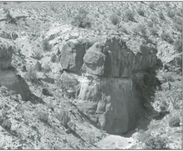
Stop 1.1: Overview of Henry Mountain Intrusive Centers The fi ve intrusive centers of the Henry Mountains are vis-ible from this point (Fig. 1). Looking due south along the road (and calling this 12 o’clock), Mount Holmes is at 12, Mount Ellsworth at 12:30, Mount Hillers at 1, Mount Pennell at 3, and Mount Ellen at 5. Each of these intrusive centers is composed of many component igneous intrusions. Mounts Ellsworth and Hol-mes are the smallest intrusive centers, and the exposed igneous rocks are composed of dikes and sills and a few relatively small laccoliths. Sedimentary rocks dominate the margins and can be traced almost to the top. The sedimentary layering is steeply inclined, indicating that more igneous rocks are beneath. Mount Ellen is the largest of the three northerly mountains and all three
5 km
Mt Hillers
Mt Holmes
Mt Ellsworth
Mt Pennell
Mt Ellen
Stop 1-1 Upper Jurassic Lower Jurassic Triassic Cretaceous Intrusions Utah Salt Lake City Henry Mts Border of the Colorado Plateau Rt. 95 Rt. 276 Hanksville 110°30'W 110°45'W 38°N 37°45'N Fig. 2Figure 1. Regional map showing the area of study (small rectangle), Stop 1.1, and the fi ve intrusive centers and peaks of the Henry Moun-tains, Utah.
are composed of a great many intrusions with a wide range of sizes and geometries. The sedimentary layering is best exposed at the base of these intrusions and intermittently exposed through the middle elevations at various dips.
On the east fl ank of Mount Hillers, the Black Mesa and Sawtooth Ridge intrusions are visible on the skyline (Fig. 2). A sheer cliff forms the east side of the Black Mesa bysmalith and Sawtooth Ridge is noted by its prominent jagged edge against the skyline. Directly in front of us (middle ground), the Trachyte Mesa intrusion is exposed. The Maiden Creek sill is exposed just east of Black Mesa. Our strategy is to visit the least-developed intrusions fi rst (i.e., the earliest stages in a possible continuum of develop-ment of an infl ating magma chamber and/or intrusion), and visit the more-developed intrusions later. From here we visit the Maiden Creek sill for Stops 1.2–1.8, break for lunch, and then spend the afternoon at the Trachyte Mesa laccolith for Stops 1.9–1.13. Directions to Stop 1.2
Continue south on Rt. 276. At mile 6.7, turn right onto dirt road. This is immediately (<100 m) before mile marker 7 on
Utah Hwy 276. At mile 9.7, park on side of dirt road where road turns SE and there is some room to park in the bend. Walk ESE down the stream valley for ~0.5 km (Fig. 3) until igneous rocks are seen in the stream bottom.
Part I: The Maiden Creek Sill
Stop 1.2: Composition and Top Contact of the Maiden Creek Sill
GPS (UTM): 536090, 4195836, zone 12, NAD27. Main points: (1) Composition and texture of the Maiden Creek sill. (2) The geometry of the body is a thick (~25 m) sill. (3) The top contact contains solid-state fabric in the uppermost ~3 cm, the remainder of the intrusion contains magmatic fabrics. Lineation and foliation are generally parallel in both fabric types.
This stop provides a good spot to view the basic cross-sec-tional geometry of the Maiden Creek sill (Figs. 4 and 5). The planar-horizontal top contact of the intrusion with the overlying Entrada Sandstone is well exposed here. We will soon examine the planar-horizontal bottom contact of the intrusion in the steep-walled gorge ~150 m east of here. The intrusion is generally ~25 m thick but thins toward its margins in some areas. The horizontal, concordant top and bottom contacts of the intrusion lead us to call this a sill. However, the map view geometry of the intrusion is con-siderably more complex, as will become apparent shortly.
This stop also provides an introduction to the igneous rock of the Henry Mountains, which is a mostly homogeneous pla-gioclase-hornblende porphyry in which phenocrysts of feldspar and amphibole lie in a very fi ne-grained gray matrix (Fig. 6; see also Hunt, 1953; Engel, 1959; Nelson et al., 1992). In the Maiden Creek sill, feldspar phenocrysts make up 30%–35% of the rock by volume and are generally euhedral laths 0.2–1 cm in diameter. Amphibole phenocrysts make up 5%–15% of the rock by volume and are euhedral needles 0.1–0.5 cm in length. Other phenocrysts include euhedral to subhedral oxide grains, which generally have a maximum diameter of 0.2 mm and make up <2% of the por-phyry by volume, and apatite and sphene, both of which are generally euhedral and <1% by volume. The very fi ne-grained matrix generally makes up 50% or more of the rock and is com-posed of microcrystalline feldspar, amphibole, and oxides.
Because of the well-exposed upper contact of the intrusion at this location, we can examine the relationship between the contact and fabric development in the igneous rock. The outer-most ~3 cm of the intrusion generally have well developed solid-state fabric, which is defi ned here by the cataclastic stretching of feldspar and amphibole phenocrysts (Fig. 6C). These deformed phenocrysts defi ne a prominent lineation. More than ~3 cm from the contact, solid-state fabric is essentially nonexistent and mag-matic fabric is developed instead. This magmag-matic fabric is defi ned by the preferential alignment of undeformed phenocrysts, partic-ularly elongate amphibole crystals (Fig. 6B). In locations where both solid-state and magmatic fabrics are exposed, foliation and lineation orientations in both fabric types of fabric are generally
276 6000 5500 6500 7000 5000 500 0 0 0.5 1 km N
Contour Interval = 100 feet
Trachyte Mesa Black Mesa Maiden Creek Sawtooth Ridge Area of Figure 9 Area of Figure 18 Area of Figure 3 dirt roads
Figure 2. Topographic map of the area NE of Mount Hillers showing the satellite intrusions to be studied on this trip.
parallel. These same observations will be seen on the margins of the Trachyte Mesa laccolith.
Directions to Stop 1.3
Head NE down the N side of the creek (Fig. 3) for ~100 m until you are on relatively fl at-lying sedimentary rocks. You should have an overview (looking S across the stream bed) of the N-facing side of the stream canyon and ~4 m high towers on the N side of the streambed.
Stop 1.3: Lateral Terminations
GPS (UTM): 536186, 4195897. Main points: (1) There are two bulbous terminations on the lateral margin of the sill, sug-gesting different magma sheets. (2) There is upward tilting of wall rocks on the margin of the intrusion. (3) This margin belongs to an NS-elongated part (fi nger) of the Maiden Creek sill.
Looking S from this vantage point, the lateral contact of the intrusion with the surrounding Entrada sandstone is beauti-fully exposed (Fig. 7A). The contact is complex; it is composed of two vertically stacked bulbous igneous terminations. As we will observe at other locations on the intrusion, this geometry is typical of most exposed lateral contacts of the Maiden Creek sill. We suggest that this geometry is most easily produced by the
stacking of separate igneous sheets, and two separate sheets can be observed at Stop 1.8.
The relationships between the sedimentary host rock and the intrusion are better preserved at this location than at most others on the Maiden Creek sill. The sediments here tilt upward above each of the upward-facing portions of each bulbous sheet termi-nation (Fig. 7A). This observation indicates that at least some of the host-rock displacement necessary for emplacement of the intrusion is accomplished through tilting of the sediments.
The lateral margin exposed here forms the eastern edge of a NS-elongated portion of the Maiden Creek sill (which we will refer to as a fi nger, following Pollard et al., 1975) that projects out from the main body of the intrusion. The ridge immediately E of here is defi ned by another NS-elongated fi nger. The lateral contact we have been considering and others in this area require that the current geometry of the fi ngers is very similar to the orig-inal emplacement geometry, i.e., these fi ngers were not formed by erosion of a once-contiguous sheet.
Directions to Stop 1.4
Head (~100 m) ESE down to the streambed and continue through Secret Nap Spot gorge until you encounter a 10 m drop along the streambed.
276 1-2 1-3 1-4 1-5 1-6 1-7 1-8 7000 5000 5100 5200 5300 5400 5500 5300 5100 5200 5400 5200 5300 5400 4900
N
0 500 mpark
path CI = 20 ft 536 000 4196000 537 000 contactFigure 3. Topographic map of the Maiden Creek sill area with stops indicated. The dashed-dotted line shows the approximate path to be walked.
Stop 1.4: Cross Section in Secret Nap Spot Gorge
GPS (UTM): no GPS measurement is possible here. Main points: (1) Complete cross section of one fi nger. (2) Bottom con-tact is conformable and not deformed. (3) No stoping visible in the igneous rock.
Exposed at this stop is a complete cross section through one of the fi ngers of the Maiden Creek sill (E side of Fig. 5C). Although overlying sedimentary rocks are not clearly exposed atop the cliff faces here, they are in place nearby, as we will observe en route to a later stop. Examining the cliff faces, it is clear that there are no xenoliths of sedimentary rock within the intrusion. Sedimentary xenoliths are exceedingly rare in all of the intrusions we will be examining. This suggests that stoping is not an important space-making mechanism in these intrusions.
Also exposed here is the concordant horizontal bottom contact of the Maiden Creek sill with the underlying Entrada Sandstone (here a shale). The bedding in the host rock below the contact is essentially undeformed.
Clear evidence for three fi ngers (like this one) exists on the margins of the Maiden Creek sill and strong evidence for a fourth
fi nger (which we were atop at Stop 2) exists. Preserved contacts demonstrate that the fi nger-like lobes project out from the main body of the intrusion and are not merely erosional remnants of a main body that was once larger and has been dissected by streams. No clear textural boundary exists between the main body of the intrusion and the fi nger-like lobes.
Each fi nger is 200–400 m long and is distinctly elongate with respect to both its cross-sectional thickness and map view width (Figs. 5A and 5B). In longitudinal cross section (Figs. 5C and 5D), each fi nger thins progressively away from the main body. The fi nger shown in Figure 5A thins from ~30 m thick near the main body to ~7 m thick over a distance of ~400 m. This thinning occurs as the base of the intrusion cuts up through the sedimentary section while the top of the intrusion resides at a consistent bedding-parallel stratigraphic level.
Directions to Stop 1.5
Backtrack out of the gorge and then walk ~175 m NW up a smaller canyon developed in sedimentary rocks. Walk up the creek bed until igneous rock is encountered.
4196000 m N 536000 m E porphyry overlying sediments underlying sediments known contact close contact inferred contact station sediments at the same structural level as the intrusion
N 0 50 100 m 1-2 1-3 1-4 1-5 1-6 1-7
Figure 4. Geologic map of the Maiden Creek sill with stops indicated.
Stop 1.5: Igneous-Sedimentary Contact on a Lateral Termination
GPS (UTM): 536186, 4196016. Main points: (1) Solid-state deformation occurs locally on lateral contact. (2) Very little deformation or metamorphism occurs in wall rocks.
The lateral contact of the intrusion with the host rock is exposed at this stop. Solid-state fabric in the outermost few centi-meters of the intrusion is prominently developed. In general, the solid-state fabric patterns are complex and probably refl ect the nature of the emplacement process, which accommodated both lateral and vertical expansion and longitudinal propagation of the sheet. As we observed at Stop 1.2 atop the intrusion, fabric patterns at the top (and bottom) contacts tend to be more consis-tent and predictable than those observed at the lateral contacts. This difference is presumably related to the more complex fl ow present in the bulbous lateral sheet terminations than that pres-ent at the planar top and bottom margins of the sheet. Similar relationships are seen at Trachyte Mesa laccolith, i.e., intense deformation at the lateral margins and little to no deformation at the bottom and top margins.
Directions to Stop 1.6
Walk several hundred meters NE (Fig. 3) until cliff is encountered (edge of the intrusion). Notice along the walk the in situ horizontal sediments atop the intrusion.
Stop 1.6: Geometry of Intrusion
GPS (UTM): 536426, 4196131, Main points: (1) The Maiden Creek intrusion consists of 100-m-scale, fi nger-like intrusions that emanate from a central intrusion. (2) The top of the intrusion is relatively fl at and concordant. The bottom of the intrusion cuts up-section, resulting in thinning of the intrusion along its length (longitudinal axis). (3) Bulbous terminations are stacked upon one another, on lateral margins of main part of the sill, suggesting that different magma sheets exist throughout the area of the intrusion. (4) Meter-scale topography exists locally on the top of the intrusion.
From this vantage point, much of the eastern side of the Maiden Creek sill is visible. We will discuss several noteworthy features of the intrusion. First, looking S from here, the south-eastern fi nger of the intrusion (which we looked at in cross
4196000 m N 536000 m E A' A B' E' C' D' B E C D C C'
C
D
D D' W E N S A A'A
B
B B' NNW SSE SW NE 0 50 100 m E E' 0 100 200 m NW SEE
0 50 100 m 0 50 100 m 0 50 100 msection at Stop 4) can be clearly seen. The top of the fi nger is relatively fl at and concordant, and fl at-lying sediments are still in place in several locations atop this part of the intrusion. Although not clearly visible from here, the bottom contact of the fi nger cuts up-section along its length, resulting in thinning of the intrusion. Each of the fi ngers of the Maiden Creek sill has a similar geometry.
These fi ngers radiate from the main body of the Maiden Creek sill, resulting in a complex map view geometry (Fig. 4). The main body of the intrusion (which we are now atop) is roughly elliptical in map view and has a relatively simple sill-like geometry in cross section. This region of the intrusion is consistently 30–40 m thick. At least four separate, fi nger-like lobes project out from this main body. Each of these fi ngers is ~30–40 m thick where it begins to project out from the main body and thins progressively to a thickness of 5–10 m as distance from the main body increases (Fig. 5). These fi ngers extend 200–400 m out from the main body of the intrusion and are dis-tinctly elongate with respect to both their map view width and their cross-sectional thickness. The numerous extant lateral con-tacts with sedimentary host rock strongly suggest that the current map pattern (Fig. 4) of the intrusion is very similar to the original intrusive geometry. This complex geometry may be a common characteristic of sills in general (e.g., Marsh, 2004) because the lateral margins of most sheet intrusions are rarely as well pre-served as those seen on the Maiden Creek sill.
Also visible from this vantage is the steep eastern side of the sill. Along this cliff the intrusion is 30–40 m thick and has two well-exposed vertically stacked bulbous lateral termina-tions (Fig. 7B). The lateral contacts with adjacent sedimentary rocks are locally preserved. As discussed earlier, these bulbous lateral terminations suggest that at least two magma sheets are stacked upon one another throughout the intrusion. These two sheets can be observed individually, as they thin to the NE and separate into individual sheets for several tens of meters (NE end of Fig. 5A; Stop 1.8). These intercalated sedimentary layers are observed in a few places and are dominantly found halfway between the base and the top of the sill, at the same location where the two bulbous terminations meet. Rare igne-ous-igneous contacts can also be traced from these screens of wall rock (Fig. 7C). These internal contacts are marked by a 1–2 cm zone of intense foliation and solid-state deformation. We will not visit the outcrop illustrated in Figure 7C, because one must climb down this cliff face, but we will see the two separate sheets from the road on Stop 1.8.
One fi nal feature visible from here is the locally developed m-scale topography of the top surface of the sill. Nascent dikes extending up from the roof of the intrusion occur in two places (one visible just W of here, the other on the NW exposed corner of the intrusion). Also present are m-scale ridges, generally ori-ented parallel to the strike of the edge of the intrusion. Johnson and Pollard (1973) interpreted similar ridges atop the Trachyte Mesa intrusion to record the position of the edge of that intrusion at various stages of progressive emplacement.
A
Figure 6. Microstructures in the Maiden Creek sill. (A) Field photo of solid-state fabric developed at contact. (B) Magmatic fabric. Photo is ~1.5 cm across. (C) Solid-state fabric. Photo is ~0.5 cm across. White streaks represent plagioclase phenocrysts that have been cataclastically altered to a much fi ner grain size and extended along the foliation.
B
Directions to Stop 1.7
Walk 200–300 m N, essentially on the top of the intrusion. Head for the overlook of a gully between two prominent NE-SW–oriented ridges (Fig. 3).
Stop 1.7: Emplacement of the Maiden Creek Sill
GPS (UTM): 536494, 4196351. Main points: (1) Magmatic fl ow is subparallel to the fi ngers. (2) Areal extent of the fi rst sheet seems to have controlled the lateral extent of the second sheet. (3) Emplacement occurred primarily by upward vertical move-ment of the roof rocks although there are still space problems.
The gully below us to the N is bordered by two ridges, each of which is held up by a fi nger of the Maiden Creek sill. Excellent lateral contacts of both fi ngers are preserved at the SW end of this gully (see Figure 15 in Pollard et al. [1975] for a photograph of a portion of one of these lateral contacts).
Because we believe the current outcrop pattern corresponds to the original shape of the sill, an ideal opportunity exists to study the relationships between igneous fabric, emplacement
processes, and intrusion geometry. Fabric results described here are summarized from Horsman et al. (2005), who used several techniques to analyze the fabric within the sill. Throughout the intrusion, solid-state fabric is confi ned to the outermost ~3 cm of the intrusion (and the few internal contacts adjacent to the screens of wall rocks). At distances greater than ~3 cm from the contact with the sedimentary host rock, magmatic fabric is almost exclusively developed. The boundary between the regions of solid-state and magmatic fabric is gradational over 1–2 cm.
Magmatic fabric is a more reliable tool than solid-state fabric for studying magmatic fl ow during emplacement because the solid-state fabric records both magmatic fl ow and the inter-action of the magma with the wall rock. Solid-state fabric is consequently more complex and diffi cult to interpret than mag-matic fabric, which refl ects primarily fi nite strain produced by the late-stage magmatic fl ow during emplacement (Horsman et al., 2005). With these caveats in mind, the fabric results for the Maiden Creek can be considered.
10 m
B
5 mA
C
ig sed ig ? ? ig sed sedFigure 7. Field photos. (A, B) Annotated photograph of lateral termi-nations on the Maiden Creek sill. (C) Internal contact between two magma sheets. ig—igneous; sed—sedimentary.
Magmatic lineation in a fi nger of the sill is generally subparal-lel to the elongation direction of the fi nger (Fig. 8). Field-measured lineations and AMS (anisotropy of magnetic susceptibility) linea-tions are generally subparallel (for the details of the fabric and a discussion of the AMS see Horsman et al., 2005). Magmatic foliation in the fi ngers is generally sub-horizontal. Consistent magmatic fabric patterns are also observed in the main body of the sill, where magmatic lineation tends to be oriented roughly radial and foliation is generally subhorizontal. We interpret these patterns to record general fl ow of magma away from an unexposed source region to the W into the main body and then out of the main body and into each fi nger. Although, we cannot distinguish whether the fi ngers are late ancillary intrusions fed by the main body, or if the main body is a region that has coalesced into a sheet of magma by spreading between early fi ngers (e.g., Pollard et al., 1975).
We infer that the Maiden Creek sill consists of two separate, sequentially emplaced sheets that were emplaced as different pulses of magma. The two sheets have almost the exact same geometry and extent. Their similar cross-sectional geometry allows us to conclude that the pulses of magma were essentially identical
in volume. This observation suggests that the emplacement and extent of the fi rst sheet controlled the extent of the second sheet.
We envision the following scenario. The emplacement of the fi rst sheet produces a weak, hot region surrounding the igne-ous body. During intrusion of subsequent igneigne-ous sheets, the adjacent heated sedimentary rock will be relatively weak and will fail before nearby cooler sediments. Consequently, after the emplacement of the fi rst sheet, subsequent pulses of magma from the same feeder system intrude immediately adjacent to the pre-viously intruded sheet. By this process, a thick sheet of igneous rock with a complex lobate three-dimensional geometry is built. The consequence is that the amount of magma intruding at any one time remains small.
Uplift of overlying roof rocks is the dominant space-making mechanism. However, when viewed in cross section, there does not seem to be enough defl ection of the layers on the margins (layers that rotate up at the contact with the Maiden Creek sill) to accommodate the amount of vertical space required by the thick-ness of the sill. This observation indicates that other mechanisms, such as lateral displacement and strain of adjacent host rocks (as
4196000 m N 536000 m E lineation plunging <5 lineation plunging >85 lineation plunging 32-58 lineation plunging 5-31 lineation plunging 59-85 9 966 967
AMS Figure 8. Macroscopic lineations and magnetic lineations
(insert) on top of the Maiden Creek sill. AMS—anisot-ropy of magnetic susceptibility.
we will observe at the Trachyte Mesa intrusion) may be respon-sible for some of the additional space making.
Directions to Stop 1.8
Head W (contouring) until the road is seen. Walk to road and then southward to car. Turn cars around and head back N and E on dirt road until intersection with Utah Hwy 276. Set odometer
to zero and turn right (S) on Hwy 276. Drive ~0.6 mi and park on
the side of the road (Fig. 3). Look to the W toward the top of the mesa that terminates close to the road.
Stop 1.8: Separate Fingers of the Maiden Creek Sill
Main point: (1) Separation of the Maiden Creek sill into an upper and lower fi nger supports our model of two pulses of magma sheeting, one stacked upon the other.
Looking up at the top of the mesa, from the W to the E, the NE fi nger of the Maiden Creek sill splits into an upper and a lower fi nger. These two thinner fi ngers extend for several tens of meters before terminating at the same lateral extent, and they both terminate along similarly oriented faults. A several-meter-thick,
horizontal sedimentary block separates the two fi ngers (Fig. 5A). To the W of this intercalated sedimentary block, within the one thick (stacked) fi nger, a 2–3 cm thick, solid-state, igneous-igneous contact can be traced from the edge of the block for several tens of meters and defi ne the boundary between the lower and upper fi n-gers. Immediately to the E of the termination of these two fi ngers, another very thin sheet appears, at a topographic level intermediate between the upper and lower fi ngers and extends for several tens of meters before thickening at the margin of the mesa. We suggest that the separation of one thick fi nger into an upper and a lower fi nger, as well as the internal contact to the W of this split, sup-ports our hypothesis that the Maiden Creek sill was constructed by stacking two sheets that share the same areal extent.
Part II: Trachyte Mesa Laccolith
Directions to Stop 1.9
Set odometer to zero. Turn around and head back N on
Utah Hwy 276. At mile 1.6, just beyond (N) the rise in the road, turn left and drive SW onto a dirt road (Fig. 9). At mile 2.0, stop
276
A
A'
4900 5000 5100 5100 5200 5000 5000 5000 4900 field trip stopmag. anomaly traverse
N
Contour Interval = 20 feet
0 500 m Qa dominantly alluvium Tp porphyry (Oligocene) Js Summerville Fm Je dominantly Entrada Fm Quaternary (?) Tertiary Jurassic Je Je Je Je Je Je Js Js Qa Qa Qa Qa Tp Tp Tp? (some alluvium)
a
park walk a b ca
b
c
536 000 537 000 4199000 4200000?
?
1-9 2-1 2-2 2-3 1-9 1-11 1-10 1-12 1-13Figure 9. Topographic map of Trachyte Mesa laccolith with stops indicated.
on the dirt road when it approaches within ~40 m of a gully north of the road (Stop 1.9). Looking ~NW across the gully, there is a clear exposure of a meter-thick sandstone bed inter-calated with igneous sheets at the top margin of the Trachyte Mesa laccolith.
Stop 1.9: View of the Southeast Margin of the Trachyte Mesa Laccolith
GPS (UTM): 536703, 4199129. Main point: Intercalated beds of Entrada Sandstone and igneous sheets within the margin of the Trachyte Mesa laccolith.
This is an excellent view of the sheeted nature of the Trachyte Mesa laccolith and the subhorizontal basal contact (Fig. 10). The cliff face below the intrusion is the red sandstone of the Entrada Formation. The thickest and lowest sheet of the Trachyte Mesa laccolith is 8 m thick here. Directly above this basal sheet is a 1-m-thick bed of Entrada sandstone. Directly above this sandstone layer are at least two more sheets. These two upper sheets have distinctively different erosional morphologies.
Directions to Stop 1.10
Continue SW on dirt road for ~0.2 mi. Park at clearing by large juniper tree. GPS (UTM): 536254, 4198926. The road becomes less traveled beyond the juniper tree. At this point, the fi eld trip will continue by foot. Head in direction 330 (azimuth) directly toward Bull Mountain (the last peak along the range moving toward the NE) on the E fl ank of Mount Ellen. Continue for ~300 m until you intersect streambed. Walk downstream until the bed of the stream is igneous rock.
Stop 1.10: Top Contact of the Trachyte Mesa Laccolith GPS (UTM): 536086, 4199194. Main points: (1) The com-position and texture of the Trachyte Mesa laccolith is very simi-lar to the Maiden Creek sill. (2) The upper igneous contact with undeformed and unmetamorphosed sandstone is well exposed. (3) The sandstone layer on the top contact here can be traced over much of the top of the laccolith.
This outcrop is assumed to be very close to the southern extent of the laccolith. The top contact is exposed and dips to the SW beneath sedimentary strata of the Entrada Formation. The thickness of the intrusion increases greatly from SW to NE along the streambed as the top contact rises 20 m over a lateral distance of 100 m. The base of the intrusion is not exposed, but it is assumed to be very shallow (<2–3 m) beneath the southwest-ernmost exposure of igneous rock. We assume this because the basal contact is exposed to the NE, outside of the stream gorge, along the cliff that was viewed from the road driving in.
The top several cm of the contact of the Trachyte Mesa lac-colith has been eroded at this location. At other locations where the actual top of the intrusion has not been eroded, there is a 2– 3 cm thick carapace of solid-state deformation. Very limited (sev-eral cm or less) erosion occurred here, evidenced by the upper contact with the sedimentary rocks exposed on the hillside.
The texture and composition of the Trachyte Mesa laccolith is very similar to the Maiden Creek sill. The rock has a micro-granular porphyritic texture with euhedral phenocrysts (up to 7 mm) of hornblende and plagioclase. The groundmass consists dominantly of microlaths of plagioclase and oxides (mostly mag-netite). Most of the plagioclase phenocrysts exhibit concentric zonation. Many of the hornblende phenocrysts and larger oxides are partially or completely altered to fi ner-grained oxides and calcite. A few pyroxene and apatite phenocrysts are observed.
The sandstone at the upper contact is unmetamorphosed and undeformed. Although, within several cm from the intrusion, we often observe pea-sized nodules within the sandstone that resist weathering. We can observe this feature here at the base of the sandstone layer. These nodules of sandstone have their pore spaces fi lled with calcite cement. Many of the oxides and hornblende in the igneous rock have also been replaced with calcite, documenting the fl uids that passed through these rocks syn- to post-emplacement.
The sandstone layer is full of cm-scale holes and larger cavities. This spheroidal weathering seems to be a marker for this particular sandstone layer. We can trace this weathered ~1-m-thick sandstone layer over the top of the Trachyte Mesa laccolith and over to the NW margin.
Directions to Stop 1.11
Walk downstream for 150 m, through a gorge that turns to the SE and just past a 1 m drop in the creek bed and continue onto two large (~4 m) boulders for an overview.
Stop 1.11: Differential Erosion of Sheets
GPS (UTM): 536236, 4199158. Main points: (1) There is geomorphic evidence for multiple intrusive sheets. (2) The basal sheet sheet 2 sheet 3 sandstone Entrada sandstone south side, Mt. Ellen
Figure 10. Photo of sandstone bed intercalated with igneous sheets, SE margin of Trachyte Mesa laccolith. Basal sheet is 8 m thick.
sedimentary layer beneath the intrusion is a massive sandstone layer. (3) The basal contact is concordant and climbs upward to the SE because the sedimentary beds are tilted down to the NW.
The walls of the gorge we just walked through weather differ-ently at different elevations. The upper part of the gorge, on both sides, is eroding and producing vertical cliff faces with multiple vertical joint faces. Approximately halfway down, both walls of the gorge step toward the center of the gorge. Several meters downward, the gorge walls become vertical once again. This differential erosion is best expressed on the N side of the gorge, where the jointing is also different between the top, middle, and bottom sections of the gorge walls. The middle section, which resists erosion and where there are very few joints, also increases in thickness gradually from the W to the E (down stream) and resembles a sill. We interpret this erosional profi le as resulting from different igneous sheets. The differences in jointing within each “step” down the walls of the gorge are at least suggestive that these “steps” cooled at different rates or at different times. Basalt fl ows are routinely differentiated using differences in ero-sional profi les and differences in jointing. Cañón-Tapia and Coe (2002) were able to differentiate several different basalt fl ows along the Columbia River using AMS, which supported their identifi cation of the fl ows based on textural, jointing, and ero-sional differences. However, we have found no textural evidence along the walls of this gorge for different sheets. Our AMS data (unpublished and not shown here), taken along multiple vertical profi les along the walls of this gorge, does not reveal any differ-ences that may indicate distinct sheets.
At the E edge of the gorge, the stream cuts through the mar-gin of the laccolith. Where the streambed changes from igneous to sandstone is a small (<1 m) cliff. Standing on the edge of the cliff, the basal contact is not exposed on the cliff wall below, but looking SE at the contact on the far cliff-face the basal contact is well exposed and much higher on the cliff face than your feet on the bottom of the gorge. The same abrupt rise in the base is observed on the distal parts of certain fi ngers of the Maiden Creek sill. Here, the contact is concordant and bedding is actually dipping 9° to the NW. This NW dip to the bedding is consistent with the observation that the NW margin of the Trachyte Mesa laccolith is several tens of meters lower, topographically, than the SE margin. The top surface of the NE half of the Trachyte Mesa laccolith also dips to the NW. The top surface of the Trachyte Mesa laccolith in the SW has a relatively fl at top.
This massive sandstone layer found beneath the contact is observed wherever the basal contact is exposed. The base of the Trachyte Mesa laccolith is exposed around most of the SE margin and in a few places around the NW margin. Because the 1-m-thick sandstone layer is usually observed at the upper contact (except for Stop 1.12), and the massive sandstone layer is always found at the base, we believe the Trachyte Mesa laccolith is largely emplaced at the same stratigraphic level throughout its extent.
Position yourself on the edge of the small cliff again and again look SE at the far cliff face. The top contact is also exposed on the cliff face and reveals a much thinner part of the Trachyte
Mesa laccolith than in the gorge. This part of the Trachyte Mesa laccolith is actually a NE-oriented fi nger, one of four such fi ngers along the SE margin. We will view the termination (cross-sec-tional view) of this fi nger from Stop 1.12.
Directions to Stop 1.12
Head back upstream toward Stop 1.10, but turn N up a tributary gorge after ~40 m. Head ~50 m up this gorge until you are on the top of the Trachyte Mesa laccolith. Walk ENE toward 075° for ~250 m to the cliff that marks the SE extent of the mesa. Find the only place along the cliff-face where you can scramble down several meters without scaling the cliff. You will also fi nd 1-m-thick blocks of sandstone along the top edge of the cliff face here. This is the cliff face we saw from Stop 1.9 (on the dirt road coming in) that has sandstone between sheets of the Trachyte Mesa laccolith.
Stop 1.12: Sheets, Fingers, and Intercalated Sandstone along the SE Margin of the Trachyte Mesa Laccolith
GPS (UTM): 536322, 4199495. Main points: (1) This margin of the Trachyte Mesa laccolith is composed of several sheets. (2) Early sheets are full of cataclastic bands and may be a result of the emplacement of later sheets, which are undeformed. (3) The contact between sheets is marked by a thin, solid-state shear zone. (4) The sheets erode differentially here, producing an irregular erosional profi le. (5) The 1-m-thick sandstone layer, usually found at the top contact, is intercalated with thin igneous sheets near the top of the mesa. (6) Looking across the valley to the SW, we see the end of the fi ngers that we saw from the side at Stop 1.11. These fi ngers are similar in shape to the ones observed at the Maiden Creek sill.
Immediately SW of the sandstone blocks that are interca-lated with higher level sheets, scramble down the margin several meters. Look SW at an irregular cross-sectional view of the rocks that make up the top-margin of the mesa here. Figure 11
is a photo of these rocks and outlines the borders of the sheets as they form the margin of the mesa. The middle sheet is ~1 m thick and undeformed. The top and bottom contacts are marked by a 2-cm-thick solid-state shear zone of intense foliation defi ned by aligned plagioclase crystals that are cataclastically crushed and elongated. These contacts between these sheets can be traced for at least 100 m to the SW. The sheets below and above are full of cataclastic bands that do not cross into the middle sheet. This brittle deformation suggests that emplacement of this middle sheet involved high strain and/or emplacement rates or that the magma already there had crystallized to a greater degree than the incoming sheet. In either case, the deformation supports forceful emplacement of the middle sheet. Clues to the mechanisms of forceful emplacement will be observed at Stop 2.1.
Scramble up to the top of the cliff again and walk several meters NE to examine the 1-m-thick sandstone blocks inter-calated between sheets. Note how they are undeformed and unmetamorphosed and resemble the sandstone layer on the top contact observed at Stop 1.10. This may indicate the although
most of the laccolith was emplaced at the same stratigraphic level (just below this sandstone layer), some thin higher-level sheets were emplaced just above this sandstone layer.
Look to the SW, across the valley below, at the southernmost fi nger that extends toward the NE (obliquely toward the viewer). Erosion reveals a cross-sectional view of this fi nger, which resem-bles two fi ngers side-by-side in shape (Fig. 12). Sedimentary wall rocks are immediately to the left (SE) of this “double” fi nger. The shape of these fi ngers resembles the fi ngers at the Maiden Creek sill. Approximately 15 m to the N of this exposure is another fi nger extending along the same trend (NE), but this fi nger is thinner. The link from this fi nger to the “double” fi nger is unclear.
Directions to Stop 1.13
Walk due N for ~400 m to a small rise in the center of the Trachyte Mesa laccolith where there is a view of the NE half of the laccolith.
Stop 1.13: Plateaus (Sheets?) on Top of the Trachyte Mesa Laccolith
Main point: (1) The top of the Trachyte Mesa laccolith is composed of several plateaus. We suggest that these plateaus may be magma sheets.
The top of the Trachyte Mesa laccolith is characterized by a series of small-scale plateaus and ridges. On the scale of the intrusion, these features are small irregularities on a relatively fl at surface. On the outcrop-scale, relatively fl at areas (hundreds of square meters) are often terminated by an escarpment, which rises up several meters (or less) to the next plateau or defi nes an elongate ridge. Ridges can be curved or straight and are continu-ous for several hundred meters.
Looking to the NE from Stop 1.13, we can identify two main plateaus that shape the top of the NE half of the mesa. Looking to the ENE, the fi rst plateau is slightly lower in elevation and ends at the SE margin of the mesa. There is very little vegetation and abundant exposure of fl at igneous rock. This surface is slightly dip-ping to the NW. Moving to the NNE, a small (1–2 m) cliff defi nes a slightly higher, second plateau. Both of these plateaus can be traced to the NE, where they become more narrow and then further to the NE more expansive again. We suggest that these plateaus may represent individual magma sheets because their dimensions are sheet-like and they terminate along steep margins, similar to the terminations of known sheets (with wall rocks) at Maiden Creek sill. Some plateaus even terminate in bulbous margins. End of First Day
Walk SE back toward Stop 1.10 and return to vehicles. Drive ~0.5 mi NE on dirt road toward Hwy 276. Turn left on Hwy 276 and drive N 5.8 mi to Hwy 95. Turn left on Hwy 95 and drive 26 mi NNW back to Hanksville.
Day 2: Trachyte Mesa Laccolith (continued), Black Mesa Bysmalith, and Sawtooth Ridge Intrusions
In the morning we will continue examining the Trachyte Mesa laccolith with a detailed look at the NW margin and in the afternoon examine the SE margin of the Black Mesa bysmalith and an overlook of the Sawtooth Ridge intrusion.
Directions to Stop 2.1
We are driving to the same location as yesterday afternoon. Starting in Hanksville, drive 26 mi S on Utah Hwy 95. Turn right
Figure 11. Sheeted outcrop at Stop 1.12. The sheet outlined by the dashed line is undeformed and 1 m thick. The surrounding sheets are cut across by abundant brittle faults. A 1–2 cm thick, solid-state shear zone marks the boundary between sheets.
Figure 12. Photo of two magma fi ngers, side-by-side at Stop 1.10 taken from Stop 1.12.
onto Utah Hwy 276 toward Ticaboo and reset the odometer. At mile 5.7, turn right onto a dirt road and drive ~0.5 mi. Park at a clearing by large juniper tree where the road becomes less traveled.
Walk in a 350° direction for ~500 m toward the NW margin of the mesa. At the edge of the mesa you will fi nd a basin that opens to NW, and you will have a cliff below you. Avoid the cliff in front of you and carefully make your way down, bearing to the SW until you are ~1/3 of the way down, and you will have an overview, looking to NE, of a thick (6 m) continuous red sand-stone bed, which rises up onto the top of the intrusion. You should be standing on igneous rock.
This is a very informative but complex outcrop, and there are several stops here. The basal and top contacts of the Henry Mountains intrusions are often observable, but this is one of the few locations in the Henry Mountains (and the only location on the Trachyte Mesa laccolith) where the wall rocks are preserved, well-exposed, and easily accessible as they are rotated upward to become the roof of the intrusion. There is also evidence for sheet-ing at this location and evidence for the relative timsheet-ing of sheet emplacement and associated deformation.
Stop 2.1a: Overview of Lateral Termination
GPS (UTM): 536029, 4199604. Main points: (1) Geometry of the lateral termination of the intrusion. (2) There are sill-like sheets and tongue-like sheets exposed here.
The edge of the laccolith is superbly exposed here. At all other margins of the Trachyte Mesa laccolith, we assume the edge of the mesa is close to the actual termination of the lacco-lith, but this is only an assumption based on the shape of the mar-gin (in many places the termination is bulbous). The thickness of the Trachyte Mesa laccolith is 43 m here, which is probably close to the maximum thickness. The valley fl oor is at the approximate level of the base of the intrusion. The top of the intrusion is composed of at least two, and possibly three sill-like sheets here (Fig. 13). We differentiate between sill-like sheets, which extend for tens of meters in two dimensions and are a maximum of three meters thick, versus tongue-like sheets, which resemble a tongue in shape and are only exposed at the base of the laccolith here.
Looking NE, sill-like sheets extend from the top of the mesa (in the SE) to beyond the edge of the mesa and rotate downward and form the actual NW margin of the intrusion.
igneous sheets massive red sands tone 10 m A B SE NW sandstone
Figure 13. Photo and line drawing of Stop 2.1b and 2.1c at the NW margin of Trachyte Mesa laccolith where wall rocks are preserved as they rotate upward and onto the top of the laccolith. At A, there are three stacked sill-like sheets exposed. At B, tongue-like sheets are exposed. Igneous rocks are shaded.
Most of the top sheet abruptly terminates ~1/4 of the way down the margin. The top sheet is ~50 cm thick and the termination is not tapered, but wall-like (the front surface is perpendicular to the top surface of the sheet). We assume the shape of this sheet is not erosional, but actually represents the true shape of the sheet because the thin (2–3 cm) cataclastic carapace is pre-served in many places along the top and wall-like frontal face. Further down the margin, the middle sheet (below the top sheet) continues until ~1/3 the way down to the valley fl oor and the slope of the margin becomes steeper. This sheet is irregularly eroded and is <1 m thick. The bottom sheet is also thin (<1 m) and extends slightly further down the slope. The bottom sheet may be part of the overlying (middle) sheet. In the middle third of the slope, there are sandstone layers concordant to the top of the lowest sheet with a dip-slope of ~65°. These sedimentary beds continue to the valley fl oor as a dip-slope. Note that the white colored sandstone layer is full of cm-scale holes and larger cavities similar to the sandstone layer at Stop 1.10, on the SE margin, although the sandstone layer is thinner here, possibly as a result of strain. This sandstone layer comprises the inner part of the contact zone.
The bottom third of this margin is composed of the sand-stone beds discussed above, but they are sharply cut by tongue-like igneous sheets. These tongue-tongue-like sheets are subhorizontal and are exposed for a maximum of several meters as they pro-trude outward from the sandstone dip-slope. The frontal margins of these sheets are bulbous and some form perfect hemispheres whereas some are more rectangular. Below these tongue-like sheets the sandstone layers continue to dip at high angles (60–70°), but they are intensely deformed by multiple faults and currently erode into cm-scale blocks and slivers. Thin selvages of these cataclastically deformed sandstones are found on the fron-tal margins of some tongue-like sheets where they are even more intensely faulted and sheared.
Twenty to 30 m to the NE, a ~6-m-thick massive red sand-stone layer can be seen as it rises up from a relatively fl at-lying position in the NW to become the top of the intrusion in the SE (Fig. 13). This sandstone bed rises up over the igneous sheets discussed above and comprises the outer part of the contact zone. Below this massive sandstone layer is a 3-m-thick series of thinner sandstone and shale beds. At the base of this 3-m-thick series is a 50-cm-thick sandstone bed that marks the inner contact zone. The actual contact with the intrusion is intensely sheared and faulted, and there are bedding plane faults between most or all of the different sedimentary layers here. The intrusion is also intensely sheared at the contact here and locally pieces of sand-stone and porphyry are mixed and sheared into a fi ne grained, intensely foliated rock.
It is important to note that the sandstone beds at the immedi-ate contact with the laccolith, in the middle portion of the slope, have a much higher dip than the massive red sandstone does on the outer part of the contact. We suggest this attests to the resis-tance to bending of the thicker, and possibly stronger, massive sandstone bed and leads to a space problem between the two
layers. This space problem results in the emplacement of the tongue-like sheets and will be discussed later.
The entire hillside you are standing on, which defi nes the edge of the mesa here, is a composite of many subhorizontal sill-like igneous sheets. Most of the igneous rock (and thus most of the internal contacts) is covered by a manganese oxide coating. The irregular shape of the slope often defi nes the sheets. Look for areas of exposure along ridges and bumps that might be contacts. These sill-like sheets can be traced for many meters laterally and seem to about one m thick with a maximum thickness of 2–3 m. Contacts between sheets are 2–3 cm wide and are defi ned by a strong foliation containing highly elongated and shattered pla-gioclase phenocrysts that are parallel to the subhorizontal sheets. Some sheets are deformed by abundant cataclastic bands; some sheets are undeformed. These observations are similar to the deformation observed surrounding the sheet at Stop 1.12. There does not seem to be any order to the sequence in which the sheets have intruded. Based on the assumption that undeformed sheets are later than deformed sheets, later sheets intrude at various lev-els within the stack.
In summary, an entire cross section of the contact is revealed here. We are standing on the most inner portion, where sheets are stacked. As we move 20–30 m to the NE, the sedimentary layer-ing at the inner contact is exposed and has been rotated to high angles by the stacking of the sheets. Moving another 10–20 m NW, the outer part of the contact is exposed where a thicker sand-stone layer is rotated upward and onto the top of the intrusion. Directions to Stop 2.1b
Continue to carefully hike down the slope to the valley fl oor. Walk to the NE to examine the tongue-like sheets protruding through the sandstones at the base of the cliff discussed above. Stop 2.1b: Late Stage Magma Tongues
Main points: (1) Sheets at the valley fl oor are tongue-like in shape. (2) These tongue-like sheets intrude through inclined (not fl at-lying) sedimentary rocks and indicate that these sheets are late. (3) Sheets have bulbous shapes to their margins.
These tongue-like sheets protrude through and deform the inclined sandstones that form the margin of the laccolith here (Fig. 13). This indicates that these sedimentary layers had already been rotated to their presently inclined position prior to being intruded. Because these inclined sandstones mark the lateral termination of the laccolith, these tongue-like sheets are viewed as being very late in the emplacement of the Trachyte Mesa lac-colith (they postdate the formation of the lateral termination). In contrast, the sill-like sheets on top are concordant to the sand-stone that represents the margin, and therefore we believe those sill-like sheets represent the earliest emplacement of magma at this margin. The sedimentary rocks below the tongue-like sheets are intensely faulted and the lateral margins of some of these sheets are also marked by faults. The bulbous margin of some of these tongue-like sheets indicates they are exposed very close to their outer contact.
Directions to Stop 2.1c
Walk 20–30 m to the NE toward the massive red sandstone. Hike up the talus-covered slope between the exposed sheets to the SW and the red sandstone to the NE until you can walk onto the upper igneous sheets. You are almost at the top of the mesa here. Stop 2.1c: Early Sheet Intrusion and Deformation of Overlying Sedimentary Rocks
GPS (UTM): 536075, 4199631. Main points: (1) There is intense solid-state deformation of the upper 2–3 cm of the sill-like sheets and magmatic textures beneath. (2) The sill-sill-like sheet intrusions are early and tilted and their slickensided surfaces exhibit evidence for late slip by subsequent intrusion. (3) There is intense brecciation of the sandstone bed immediately at the contact. (4) Flexural slip occurs on bedding planes and igneous-sedimentary contacts. (5) Thinning of the massive red sandstone bed is accommodated on the grain-scale (grain size reduction and porosity collapse).
Below the slickensided polish, the uppermost contact of these sheets exhibits a 2–3-cm-thick zone where the plagioclase crystals are intensely fractured, and in places completely shat-tered into micron-scale pieces, and these pieces were dragged along the foliation. On a macroscopic scale, the very fi ne grain size of the plagioclase pieces defi ning the foliation can be easily misinterpreted as ductile deformation of the plagioclase grains. On the surface, these pieces of plagioclase are dragged to form the obvious lineation that trends NW, perpendicular to the mar-gin here. Shattered plagioclase grains have also been fl attened to form a foliation, but the lineation is much stronger than the folia-tion, similar to the magmatic fabric found throughout the main body of the intrusion.
The top surfaces of the sill-like sheets on the margin here are composed of thin (<1 cm), green (chlorite?), very fi ne grained, striated, polished surfaces forming the contact between the sheets and the sedimentary cover. This low-grade slickensided surface suggests that these upper sheets were emplaced early in the emplacement of the Trachyte Mesa laccolith, and were sub-sequently uplifted, rotated, and sheared during fl exural slip along contacts by later emplacement of the main body of the intrusion below. Supporting this hypothesis is the observation that the sedimentary layers below these sheets are also rotated into the same inclined position, presumably by the igneous mass behind them. The other possibility is that these sheets intruded late, but followed bedding planes. In this case, as the bedding rotates downward at the margin, sheets followed bedding and intruded downward as they encountered the already formed margin.
The sedimentary layers above the contact are deformed to varying degrees. Immediately above the contact, a 50-cm-thick sandstone layer is faulted and locally intensely brecciated. Some of this deformation might be related to the early emplacement of the top sheet, which terminates abruptly at this location, or it might be due to the later emplacement and infl ation of the main igneous mass. There are faults between most (or all) of the sedi-mentary layers between the contact and the massive red sandstone
layer, suggesting that fl exural slip has occurred to partly accom-modate the upward rise and rotation of these layers. Immediately at the contact, the intrusion is also intensely sheared, but only for the top few cm. Approximately one-third the distance down the margin there is a zone of mixed sedimentary and igneous rock (top sheet) that is intensely sheared. Shear bands that cut across the foliation indicate that the sedimentary rocks were moving up and over the intrusion to the SE.
Detailed two-dimensional strain analysis (normalized Fry analyses) was completed on 32 sandstone samples taken from massive red sandstone layer (Fig. 14), which is a high-porosity (>10%) sandstone. Strain ratios generally increase toward the middle and upper portions of the massive red sandstone layer and then slightly decrease at the top. Two-dimensional porosity data was also collected on most of the same samples. Porosity data was collected from photographs of grains by using a graphics program whereby the area of the pore spaces versus the area of the grains could be differentiated.
The thinning of the massive red sandstone is a result of grain fracturing and grain sliding, which induce a porosity decrease. In Figure 14, there is a correlation between the increase in strain ratios and the decrease in porosity along the massive red sandstone layer. Microstructurally, there is a qualitative increase in fractures as porosity decreases and strain ratios increase. Fractures mostly emanate from grain contacts and in the highly attenuated part some grains are completely crushed. Crushed grains are not observed from samples at the NW end of the layer. We associate all of this deformation to emplacement of sheets and subsequent vertical infl ation of the laccolith. The observation that the strain decreases as the sandstone rolls over on to the top of the intrusion is inconsistent with the “rolling hinge” model of Hunt (1953). In this model (one of three Hunt proposed for emplacing laccoliths) an already thickened intrusion advances laterally as sedimentary rocks are rolled up and over the front of the advancing massive sheet.
Return to Stop 2.1a: Evolution of a Lateral Termination
Figure 15 is our interpretative cross section of the margin at Stop 2.1. We envision an incremental emplacement model for the Trachyte Mesa laccolith whereby vertical growth occurs through stacking of magma sheets. All the sill-like sheets stopped their lateral migration at generally the same location, similar to our observations at the Maiden Creek sill. There is one outcrop of a thin sheet located ~130 m N of the base of the mesa here, and this is why we place the lowermost sheet on our cross section. There does not seem to be any order to the vertical sequence of the sheets, except that the earliest sheets have been lifted to the top of the pile (the sill-like sheets that “drape” over the margin). The vertical stacking of sheets causes the mechanically strong mas-sive red sandstone at the marginal contact to bend upward and results in a low-pressure triangle-shaped zone at the base of and in front of the marginal contact. The low-pressure zone is created because the more massive sandstone layer is thick and strong and resists bending, and therefore does not conform exactly to the
subvertical outward margin of the growing/stacking laccolith. The thinner bedded sandstones and shales immediately at the contact are more readily deformed and conform to the outermost shape of the contact. Because the magma is under high pressure, the decrease in pressure at these voids is immediately fi lled by tongue-like sheets, which at this time originate from the exterior margin of the accumulating stack. In our model, these tongue-like sheets were emplaced solely as a result of this low-pressure zone. This implies that changes in magma pressure are communicated throughout the growing body, even though the body as a whole is constructed of individual sheets. This idea of magma pres-sure communication is supported by the observation that all the tongue-like sheets at the base arrested at the same outward dis-tance from the Trachyte Mesa laccolith, even through they were midway through deforming upturned sandstone layers. Once these tongues fi lled the low-pressure zone, it once again becomes more favorable to create sheets on top or elsewhere. Therefore in our model, the location and type of sheet is partly controlled by the strength, position, and orientation of the wall rocks, which are
continually changing as more sheets are emplaced. The accumu-lation of sheets results in a fl at-topped laccolith, which is actually the most common shape for the top of a laccolith (Corry, 1988). Directions to Stop 2.2
From the edge of the mesa here, walk toward 150° for 200 m until you see an ~1-m-thick sandstone bed eroding into blocks on top of the laccolith.
Stop 2.2: Sandstone Roof of the Trachyte Mesa Laccolith Main points: (1) The current exposure of the top of the Trachyte Mesa laccolith is at or very close to the actual upper contact. (2) The same ~1-m-thick sandstone bed can be found at the upper contact on the SE, top, and NW margins, and bits and pieces of it can also be found throughout the top in the NE half of the mesa.
This sandstone bed here resembles the sandstone observed at Stop 1.10, Stop 1.12, and Stop 2.1a and is lying at the contact with the igneous rock of the Trachyte Mesa laccolith below.