JUN 27 1960
LIBRAR
DIGITAL COMPUTER STUDY OF THE EFFECTS OF MANUFACTUREDERRORS ON DYNAMIC GEAR LOADS
by.
Michael G. Meacher
B. ENG. Nova Scotia Technical College
(1959)
SUBMITTED IN PARTIAL FULFILLMENT OF THE
REQUIREMENTS FOR THE DEGREE OF
MASTER OF SCIENCE
at the
MASSACHUSETTS INSTITUTE OF TECHNOLOGY
June, 1960
Signature of the
AuthorSignature
T
-Certified by
redacted
Thesis Supervisor
Accepted by
Signature redacted
Chairman, Department Committee on Graduate Studies
V -~ '-
iq~,k)
('* ~~fi. A L) .<L A 6.1< *'~ Li iKO ;' :7
~iI
ItT> 'f
iI . A l ,
~B1IT
~3
T7 I'iIJ I~JU JILT VI T2 i U T DoA l 4U~ .. \
i fij 10 0o1uls11IE
io~dv ~x~c*qn~2 ~ie~t~T
~ei1uI&~ ~~UJbL
d)
47L0 5~'IkLnATf~ ~C~L~8C ~ irc11
N ,~ Al
- bo",li-is" --ya A -4
DIGITAL COMPUTER STUDY OF THE EFFECTS OF MANUFACTURED ERRORS ON DYNAMIC GEAR LOADS
by
Michael G. Meacher
Submitted to the Department of Mechanical Engineering on
May 24, 1960 in partial fulfillment of the requirements for the degree
of Master of Science.
ABSTRACT
A theoretical analysis was made to study the effect that the
disengagement of a tooth-pair has on dynamic loads of gear teeth. The
effect of friction was approximated by including an equivalent viscous
damping factor.
The gear teeth were assumed to have insignificant
manufactured errors compared to the deflections of the teeth under
load.
A digital computer program was written to study the effect a
manufactured error has on dynamic loads, stress and deflections of a
set of gear teeth. A concise method was used to determine the manner
in which engagement and disengagement of a tooth-pair occurs. The
non-linear variable elasticity of gear teeth was taken into account. A
damping term was included by considering an equivalent damping factor
proportional to the relative-displacement velocities of gear teeth.
Thesis Supervisor:
Title:
Herbert H. Richardson
Assistant Professor of
Mechanical Engineering
ACKNOWLEDGEMENT
The author wishes to sincerely thank those people, who
are not specifically mentioned here., for their assistance and cooperation in this investigation.
My sincere appreciation goes to Professor Herbert H. Richardson,
who acted as thesis supervisor,, for his encouragement, assistance and guidance throughout the preparation of this thesis.
The cooperation of the Hamilton Standard Division of United Aircraft Cooperation is gratefully acknowledged.
My appreciation goes to the competent staff of the M. I. T.
Computation Center for their advice and assistance.
Finally, a grateful acknowledgement is due Mr. Roy Breon for his competent help.
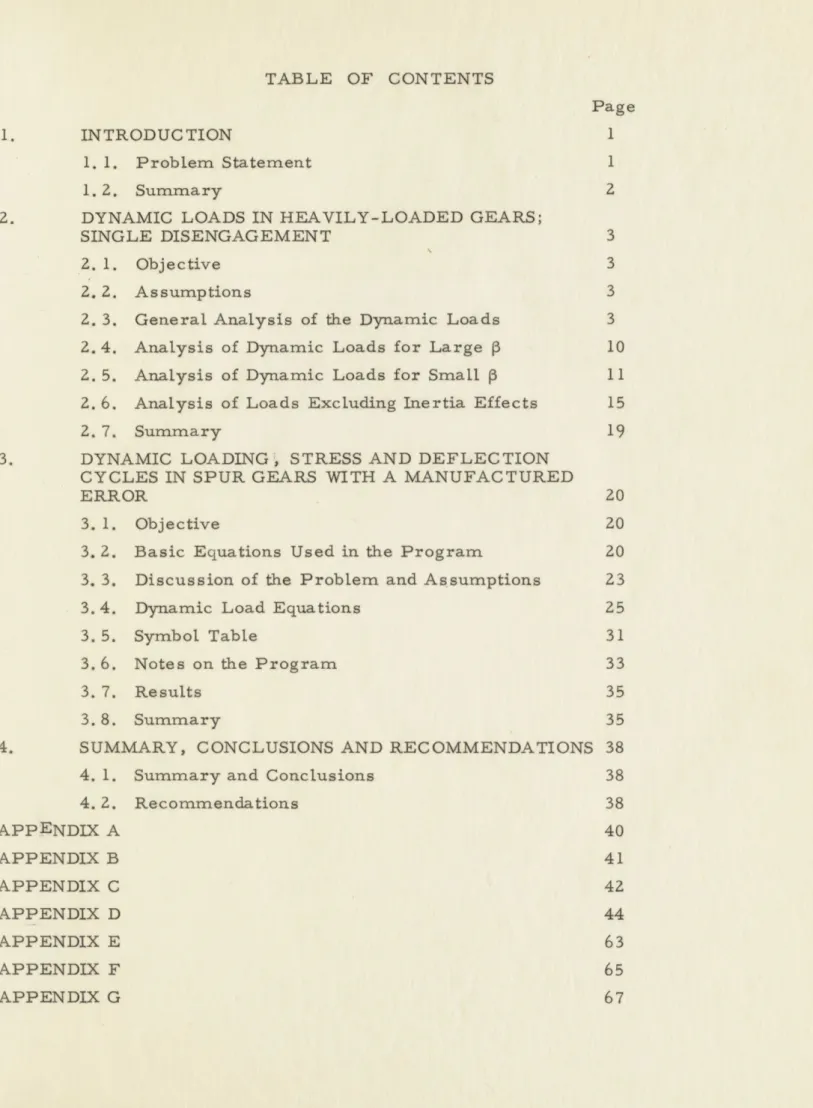
TABLE OF CONTENTS
Page
1. INTRODUCTION 1
1. 1. Problem Statement 1
1. 2. Summary 2
2. DYNAMIC LOADS IN HEAVILY-LOADED GEARS;
SINGLE DISENGAGEMENT 3
2. 1. Objective 3
2. 2. Assumptions 3
2. 3. General Analysis of the Dynamic Loads 3
2.4. Analysis of Dynamic Loads for Large p 10 2. 5. Analysis of Dynamic Loads for Small
p
11 2.6. Analysis of Loads Excluding Inertia Effects 152.7. Summary 19
3. DYNAMIC LOADING ! STRESS AND DEFLECTION CYCLES IN SPUR GEARS WITH A MANUFACTURED
ERROR 20
3.1. Objective 20
3. 2. Basic Equations Used in the Program 20 3. 3. Discussion of the Problem and Assumptions 23
3.4. Dynamic Load Equations 25
3.5. Symbol Table 31
3.6. Notes on the Program 33
3.7. Results 35
3.8. Summary 35
4. SUMMARY, CONCLUSIONS AND RECOMMENDATIONS 38
4. 1. Summary and Conclusions 38
4. 2. Recommendations 38 APPENDIX A 40 APPENDIX B 41 APPENDIX C 42 APPENDIX D 44 APPENDIX E 63 APPENDIX F 65 APPENDIX G 67
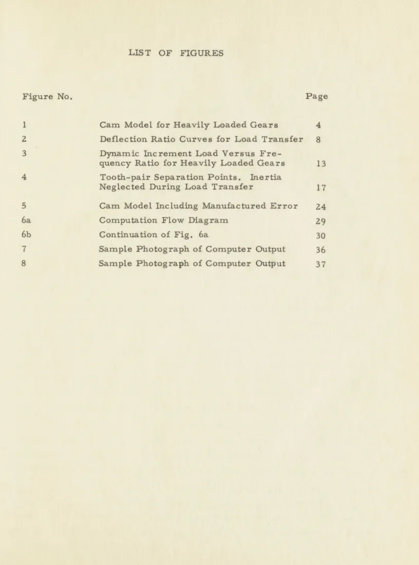
LIS T OF FIGURES
Figure No.
Page
1
Cam Model for Heavily Loaded Gears
4
2
Deflection Ratio Curves for Load Transfer
8
3
Dynamic Increment Load Versus
Fre-quency Ratio for Heavily Loaded Gears
13
4
Tooth-pair Separation Points. Inertia
Neglected During Load Transfer
17
5
Cam Model Including Manufactured Error
24
6a
Computation Flow Diagram
29
6b
Continuation of Fig. 6a
30
7
Sample Photograph of Computer Output
36
CHAPTER I INTRODUCTION
1. 1. Problem Statement
In recent years, much effort has been expended to improve the
methods of designing gears. This ha.- been brought about by the greater
demands of modern machinery for weight and volume economy, strength,
safety and reliability. Previously, design criteria depended upon
semi-empirical formulae which were not always accurate or reliable when
higher speeds and loads were required of gears. Hence, new methods
have been devised to analyze the "action" of gears in order to be able to
produce more consistant and accurate gear design information.
The design criteria of gears may be divided into the three distinct
effects of bending stress and wear in gear teeth and the temperature of
the lubricating fluid; any of which may be the limiting factor. However,
all of these criteria depend upon the loads carried by thegear teeth.
Therefore, an accurate design of gears depends upon a precise knowledge
of the loading of gear teeth when they are transmitting power.
A rigorous method for computing these loads has been devised by
1
H. H. Richardson in his doctoral thesis at M. I. T. A single-engagement
spring-mass and cam model of the dynamic gear action was presented to
study the effect of dynamic loads in a tooth-pair during single load transfer.
The oscillations of the mass caused by the load transfer were assumed to
die out before the next load transfer took place. This would be true at slow
speeds or in a critically damped system. In this analysis the damping effects
were assumed to be negligible during load transfer.
One object of this thesis is to study the effect of damping on the gear
system.
Gear action is damped mainly by the friction of the gear teeth
sliding on each other. In this analysis, an equivalent damping factor,
proportional to the relative velocity of the pitch circles was included.
The influence of manufactured errors was neglected in this analysis.
This corresponds to the case of heavily loaded gears as defined by J. B.
2
Reswick
.The gears are considered to be heavily loaded when the deflections
of the gear teeth under load are much greater than the manufactured errors
in the gears.
In order to study the over-all dynamic effects of gear
loads
in a tooth-pair, a computer must be used because of the complexity of the problem. A digital computer program was written by Wayne 0 'Neill3to solve for the dynamic loads, stress and deflections of a perfect set of gear teeth (no manufactured errors). The non-linear variable elasticity of the gear teeth was included. The parameters for speed, damping and load were varied to study the effect of each.
The second object of this thesis is to extend O'Neills program
to include the effect of a simple manufactured error on the dynamic loads, stress and deflections of the gear teeth.
One tooth of the gear is considered to have a negative error, which is defined to be that error which decreases the load in the error tooth, below the load a perfect tooth would carry under the same conditions.
This error is constant along the profile of the tooth.
The heaviest stressing in this case is on the tooth following the error tooth since that tooth comes into contact early at its tip. In this position the tooth is under its largest bending moment since the bending arm is longest and the initial load is greater than usual. It is, therefore,
this tooth which is studied.
1. 2. Summary
The object of this thesis is to:
A. Analyze the effect of damping on the dynamic loads of a tooth-pair when single-load transfer takes place.
B. Study the effect a manufactured error has on the dynamic loads, stress and deflections of gear teeth.
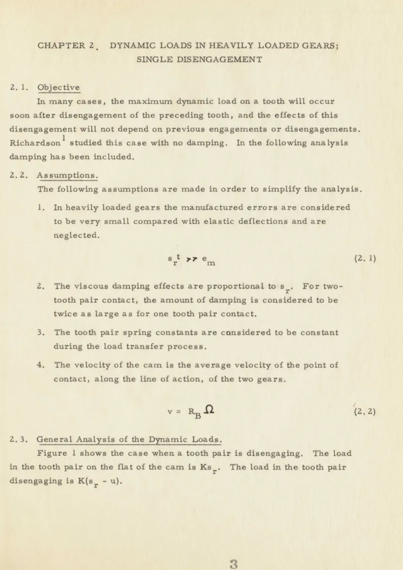
CHAPTER 2. DYNAMIC LOADS IN HEAVILY LOADED GEARS; SINGLE DISENGAGEMENT
2. 1. Objective
In many cases, the maximum dynamic load on a tooth will occur soon after disengagement of the preceding tooth, and the effects of this disengagement will not depend on previous engagements or disengagements.
1
Richardson studied this case with no damping. In the following analysis damping has been included.
2.2. Assumptions.
The following assumptions are made in order to simplify the analysis.
1. In heavily loaded gears the manufactured errors are considered to be very small compared with elastic deflections and are neglected.
srt '. e (2. 1)
2. The viscous damping effects are proportional to sr. For two-tooth pair contact, the amount of damping is considered to be twice as large as for one tooth pair contact.
3. The tooth pair spring constants are considered to be constant during the load transfer process.
4. The velocity of the cam is the average velocity of the point of contact, along the line of action, of the two gears.
V=RB .0 (2.2)
2. 3. General Analysis of the Dynamic Loads.
Figure 1 shows the case when a tooth pair is disengaging. The load in the tooth pair on the flat of the cam is Ks r The load in the tooth pair disengaging is K(sr - u).
2b hr S sr
u
I.S
-s
'
" K 0.V////////11/77/7//7
Fig. 1. Cam Model for Heavily Loaded Gears
4I
wThe dynamic equation is
m' r + 2b 9r + 2Ksr = W + Ku
The cam shape can be approximated by a curve of the form:
u = cs2 (2.4)
where
s' = s - si#d
The distance from the pitch point to actual point of disengagement is s. The distance from the pitch point to the theoretical point of disengagement is s 0d. s*d is defined in Chapter 3.
The cam constant, for 200 involute gears, can be found in Ref. 1. It is obvious that
s= vt Therefore from Eq. (2. 4) and (2. 5)
u = cv t The following quantities are now defined.
W = Ks t r
W = total load being transferred. K = spring constant.
srt = relative displacement of a tooth pair (single tooth pair contact).
5
(2. 3)
(2.5)
(2.6)
mm 2
m
== m +m1
2
1 2 2 1 R2 Ji2m
=
equivalent mass of the system at the pressure line.
RB = base circle radius.b
a
,
T
b
b m p = damping ratio.b
=
proportional damping factor.
n =
a
b =I W = naturalna
W'i naturalfrequency
frequency
V "'rbof the system with two tooth pairs in contact.
of the system with one tooth pair in contact.
.(2.
11)
p
is proportional to the ratio of the natural period of the spring-mass system
to the time required to withdraw the cam if no oscillations take place.
Equation (2. 3) is now normalized using (2. 6), (2. 7), (2. 9), (2. 10) and
(2. 11). 1 5r 2paZst
Wi) r na na r st
r + r st 2 r 22
2na
4
(2. 12)
6
(2. 9)(2. 10)
At t = 0,
=
1,
=0
st 2 st
r
r
With these initial conditions Eq. (2. 12) is solved, assuming pa
'1.
w
pt
-=e
naa
4p
2) cos V1
wPZ
t +
s rt
r3
3pa ~p
.a 3 si
7
t2 + P I- )2 2
4p
-
wp t+
-
+ -(2.
13)
2 [4 a 2 2 a na t+
Equation (2. 13) will hold until the disengaging tooth pair leaves
contact. At this point
u
2
2
2
(
- =nb t1
(2.14)Sr t Srt
st
The time at which contact is broken is defined as tl, shown in Fig. 2.
After this time only one tooth pair is in contact and a free vibration takes
place.
The equation for the dynamic effects of the single tooth pair contact
is now solved. The initial conditions from Eq. (2. 13) are:
sr
r
and
(-srti
t
==.=..==.:..::.=:==.:..===:=.=:==:oo==l
===========================Jo=
:21
===r-==========
:=iiiii uin!!iiiiininlinlii!!iiiiiiiiii iiiiiiinni!!!!iiiii!!!~A4
... ... ... !..
====~~~~~~~~~0 -WO==========
============l====m===in========ul==:===========
====i~~~~~~~~-0
00====================
!=iii-00 i!!!= i!nm w n l!!iiii!iii!ii=!! LitiniRi
!!n==N E!!!!!!===nn!!!!!!!=5!nmuuunn=!====ni=!-map! inlniini iiiiiiiiiiiiiiiiiiiiiiinii~iininliiiniinninninliiiiiiiiiiMmiiil
===
==========================iiii=i
iii!u!IiiiiiiinliN~idii= =!!iinli!!=i!!!ii==!iiiiiiiiOF
=== =========an======r-l==um=====00==
..
=================....=::=======1===iiiiin
ineiinliinn~nliilin
ali!i""'inni!iiiiin!!ii!!iii;oi~
in!!o
%I-I u
nnnn!r-- -1,-c Ad==M.. rc!
Huinsfim---H !HH1 r 2 Pb sr -s t "nb2 srt nb r Wd s r Ksrt srt r r max s + r 1 srt r + (eP b( wnb(t-t))
I
2
+ tiL
rS+ Pb whb
2
s t n s t r rwhb
Pb
(2. 16)
ti Wd = W + W whereWd = total dynamic load.
W = total static load (Eq. (2. 7)). W = dynamic increment load.
W dW -
-1+
--s. Ks rt Ks rt9
(2.15)[
/
S rl St r (2. 17) (2. 18)2. 4. Analysis of Dynamic Loads for Large
p
-To simplify the above analysis further assumptions are made. In
this section a large
P
is assumed.
A large
P
implies that the period of one natural oscillation is
very large compared to the time of disengagement. In the limit, as
p
approaches infinity, the total load is instantaneously applied to the
mass-single tooth pair system.
For single tooth pair contact the equation for dynamic loading becomes:
msr +bsr +Ksr =W
(2. 19)
Using
obtained.
-
r
2 st'nb
r
At t =0,
the parameters defined in Sec.2.3, the following equation is
+ s
r
St:r
5 + r=1s t
r
5r
1
s
- = - and = 0 5rt
2
5rt
Let
nb n Pb =I0
(2.20)
(2.21) W nd = [1Using the initial conditions and Eq. (2'. 21), the solution to Eq. (2. 20)
becomes:
-pW t Pw -nrcos
wndt +
In
sin wnt
(2.22)The maximum values of Eq. (2. 22) are desired for the various values of p. It was found that the maximum values occurred when
ndt=r
or
(2.23)n
1
= 1 + -e 2(2.24)
The values of (sr/srt) max - 1 for various damping ratios, p,
are listed in Appendix A.
These are the maximum values of Wi/Ksrt, In Fig. 3,
for large values of P .
2. 5. Analysis of Dynamic Loads for Small p
A small P implies that the periods of the natural oscillations are
small compared to the time of disengagement.
For a very small
P
the dynamic effects and viscous damping in
Eq. (2. 12) may be neglected.
Equation (2. 12) becomes:
2 2 2r
+
9
na1 t= 2 2
st 2 4 2 tnb, r(2.25)
JI
st
r1
-2e
s
s
t
rmax..--
2
Disengagement occurs at time, t2 , as shown in Fig. 2.
point,
u
s rt t r(r~
2
Therefore
2 2 2P
"nbt
2 =1
1
2
2
- + - W 0'b t2 2 2Solve for
P2
and substitute the value in
sr i st 2
r
r
Eq. 2(2.25)
1+
- -t ) t2t
2 (2.27) (2. 28)Let
PbP
tt = t = t2Therefore the equation for single tooth pair contact becomes:
eq0 S
r
2 s t r 2p 8r S-+
--n s t = 1 (2.29)
(2. 30)
srtr
12
(2.26)1
At thismFT ======1=1=========-1=Vi===A
Ir
==============I== miniliiiiiiiiiii~~~~~~~~~~~~~~A 0-iiilnni!iiiiinn~iiisilsiiiiiiiiiin n =====orEI
0====!=============
!!ii!!iiniiill iiiiiiiiiiiii!i~n!!!=!!!!!!!!!iiiiiiiin!!!!!!!inniinilOFnil====!==!===========
!!==!!!!i!=! lin!!===5ui!Enisgun=i!!nin=i!!u!!n=.00'i;ooiiiiiiii -A iiiiir nnaiiiinnnnn!iiiiiiiii I I Jiiinnii
=====nnn====Pi
.000
VM M V==========
=!uilinnini
iiiiiiiii~in~ijjisiininliiiiii!!!nilininin!=ii-00===muu===w====uuliana~~..00=============
========:==========================IF
iiilitiiiiii'OF i!!!in 2M nli!!
=
ii! i!! i=
! I ITT-11"Pl-
6 1 niu!=i===, y 1)'
731!=
Eii!uinnn!!!!!M !,==!!==!uiininininili!!i!!~ lii
~~~~
IfIn i!EilljnI!!= = !ii!ii= iiiin!======-
-
==
- -
.---======= ======
========~~~~~~~
Af I=================
iiii!!iiiiiiiiiin l~~~~~~~~~~~~~~IFi= 2!!iiin!!!!iiiiiiiiiiiini!=iiiii!
=======
~xmm~i=========mu======='OF=
======
========================e=At t' = 0,
0
s
r
r
1and -
_
srt
srt
t
With the above initial conditions, the solution of Eq. (2. 30) becomes the
following, for p 4 1
=
1+e Pwnt
st
r
s
inf1- p2
nt](2.31)
TI2
The maximum values of Eq. (2. 31) occur when
tann
p
The maximum values of Eq.
various values of p. These values
curves in Fig. 3, when
P
is small.
For critical damping (p
=
1),
becomes:
s
.=
1+
w C)t' eSt
n
r
(2. 31) are listed in Appendix B for
are used to find the initial slopes of
Eq. (2. 30) with its initial conditions
- ti
n
(2.32)
For overdamping (p ;P 1), Eq. (2. 30) with its initial conditions
becomes:
s t
r
n
p
/T-2
(2.33)
'A
s inh 172 nts
S t)
mrx
-pW t!_1+ e
np
tanh /p I~ w1t '=
_2 ~ P (2.35)The values of Eq. (2. 34) are listed in Appendix B.
2. 6. Analysis of Loads Excluding Inertia Effects
When the inertia effects are neglected, Eq. (2. 12) becomes:
2 pa s r ) s t
na
r
2 2 2+
-
+
na
srt 2 4r
(2.36)
Remembering Eqs. (2. 19), (2. 10) and the initial conditions for
Eq. (2. 12), the solution of Eq. (2. 36) becomes:
%bt
2 m
Sri12
2
- =- 4P2Pb
es t
2
r
+ 8pb2 - 4Pbanbt + wnb t2JF
(2.37)
Separation occurs at time, t1, when
S(r ti rA W
u
sr wnb ~n PbP
'5
when
(2.34)Let
Therefore
nt
1 = + e 2 + 4pwnt 8p2 8np (2.38)
p
2The solutions of Eq. (2. 38) are plotted on Fig. 4. These are the points where the tooth pair separates. Notice that for large pn, Pn approaches 1/42 and for small pn' Pn approaches 1. 0.
For a very large cnt , and small pn' Pn approaches 1. 0 but
P
a 1/wn t [ and thereforeP
will be very small. In Sec. 2. 5,P
was assumed very small. This is now justified because whenp
1. 0,then separation will occur when sr/srt Q 1. 0.
In Sec. 2.4,
p
was assumed very large. This corresponds to a small w ti and consequently a large . Pn approaches 1//Z which corresponds to an initial displacement, s rt = 1/2.However, it must be remembered that this curve can only be correctly used when mass or the inertia effects are small.
Now that the separation values are known, the free vibration of the single tooth pair is analyzed for a damping ratio of one; that is,
critical damping. It is desirable to know whether or not there is any over-shoot in this case.
Using the conditions in Eq. (2. 29) along with Eq. (2. 30), the general equation for critical damping (p = 1) becomes:
s -w t'
r
n
(.9
-= 1 + (A + Bt') e (2.39)
s t
r
The initial conditions for this equation are taken from Eq. (2. 37)
Therefore, at t' = 0, s
A -1 (2.40)
srt
I 1 1.
~~~~H
I I I IH MI i M I . L I I. U . Io11HI I
i i II I I i1
H
0
H1
I
M il 1 1 1 1. .oooo H I 1 -11 1 1 1 11 1 11 A l I 11 i 11 I .1 1 i 4 'DOV
i-
01
OT *0
Iw
.0
ITT 7116- I .~ I HI 7 1 mWM .M -M I I Im
.. 1 .1 . 1 1 H il r I~~~~~ I II H 1 I. I Il d i I H il 11 .H 1 1111 .s m .M .111 IM..a-
. 1~~~ ~~~
i H i l I t s a em .. .m o = - 2I1
=.
. rm1=.
.ti
8
sr
tiIf there is any overshoot then
sr/srt
=
0.
Therefore e-Wnt (B - wnA - B nt') = 0n
n
This occurs when
B - w A - Bw t'= 0 n n
Let
-A=
U s sV n (s t rtThen
W t' = 1 + --..
n
V
UUsing Eqs. (2. 40), (2. 41) and (2. 43) the value of V/U is calculated.
From Fig. 4, for small
P
p
and small wt
1,
w
Cnt,and large w
tj, pw
nt approaches 1.
For large
approaches
1/2T.
When PCnt =1
V1
U
4
When Pwnt
=/J7
U
1
2
18
(2.41)(2.42)
(2.43)
(2.44)
s B = r-E s r tFor all other values of wnt1 between 1 and 1/2 the values of V/U fall between 1/4 and 1/2. Within this range wnt' falls between - 0. 33
and -1 which can never be, since t' and u are always defined to be positive. Consequently for damping equal to or greater than one there will be no overshoot.
2. 7. Summary
In this chapter, the maximum dynamic load in a tooth pair was calculated for different damping ratios. The teeth were considered to be heavily loaded and one tooth pair was disengaging or moving out of
contact. For very large "P, the maximum incremental dynamic loads were plotted for various damping ratios.. Also for small P, the initial slopes of the curves, Fig. 3, were calculated. The curve for no damping was taken from Ref. 1 and the other curves were estimated, knowing the initial slope and maximum value for each damping ratio.
With inertia effects neglected, the parameters, pn and Pn were calculated at the point where separation of a tooth pair occurs. It was also shown that for critical or supercritical damping there is no over-shoot and therefore no dynamic incremental load on the gear teeth.
3. DYNAMIC LOADING, STRESS AND DEFLECTION CYCLES IN SPUR GEARS WITH A MANUFACTURED ERROR
3. 1. Objective
Wayne O'Neill, in his Master 's Thesis 3 wrote a program to be used on the IBM 704 Computer at M. I. T. This program was written
in order to find the dynamic loads, stress and deflections, in a perfect set of gears. The object of this chapter is to extend this program to include a manufactured error and to study the effect this error has on the dynamic loads, stress and deflections of spur gear teeth.
3. 2. Basic Equations Used in the Program
The following equations are essentially those derived by Richardson in Ref. 1 and are only changed in order to facilitate their use on the
Computer.
The equation for the normal pitch is:
P = .- rR cos
e
(3.1)where
R = pitch circle radius
E
= pressure angle (200i = number of teeth on the gear of radius R.
The normalized distance along the pressure line from the theoretical end of contact is:
P
n where
s = the distance measured from the pitch point, along the pressure line, to the actual point of contact of the tooth.
s = the distance measured from the pitch point, along the
pressure line, to the theoretical point of contact of the tooth
The normalized no-load separation along the pressure line is
,s cP n 2 (3.3)
P P n
where
c = the no-load separation constant or the cam constant.
The normalized theoretical distance to the initial or final point of contact is
s
Pn 2-rrcos[
sin 2 e + 4cL4a
- -
i+a
-
sinO
3
(3.4)
wherei= the number of teeth ai gear 1.
aa = addendum distance of gear 1. (Ref. 1)
soe/Pn is the normalized theoretical distance to the point of en-gagement of gear 1. In order to calculate sld/Pn, the point of disengage-ment, i1 is changed to the number of teeth on the mating gear and aa is changed to the addendum distance of the mating gear.
The theoretical contact ratio is
n
Sf,
+
d
n
The compliance of a tooth-pair, at a certain sPn , is given by
+
= (
-n
)
8+
A 7 )
+
A6
+
A
5 ( n nP n )' n) 4 3 2 + A4 s + A3s + A2s + A \ n 3 / s 1 I P+ A
0(3.6)
(3.5)
This equation was formulated by O'Neill and Skinner 3.
The Taylor
Series coefficients, A
-
A
0, were calculated by a program written by Skinner
and are presented in Appendix C for a gear and pinion of 27 and 18 teeth, respectively. Essentially this equation describes the curve of compliance in Richardson's thesis.
The bending stress in the root of the tooth being investigated is calculated from the Lewis equation which is normalized to the form below:
cb n
Ww
2
1
=-- cose
-W
y
(3.7) wherea-b = the stress in the tooth being investigated.
W
=
the total load being transmitted.
W
=
the load in the tooth being investigated.
W
=
the total load per unit thickness.
1/y
=
the Lewis Form factor defined below.
3 cos
jCosd
\Cos0/
J
i -
2CLd
-..L.i
3cos cos
Cos()
J
i i - 2d i) )2
(inve
+--i >38 teeth
i 438 teeth
where*=
0
- 2ns/iPn - r/Zi=
cos~
(cose /i-2ad/)
22
1
Y
(3.8)
The manufactured error ratio is
E
E
p
T2
-- m mpe c (3. 10) Sr P 2 cn
eUnfamiliar parameters are defined further on in this chapter.
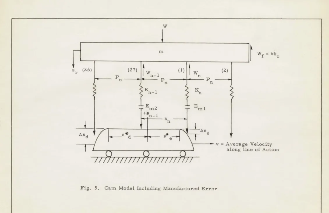
3. 3. Discussion of the Problem and Assumptions
The spring-mass-cam system in Fig. 5 is a modification of the
1
Richardson Model . Tooth-pair (n) is always considered to be engaging
and tooth-pair (n-1) is always considered to be disengaging. A cycle
starts at the pitch point of tooth-pair (n-1) and ends at the pitch point of tooth-pair (n).
Since one tooth in the gear (27 teeth) has an error, a counting system is set up to include the error once in every 27 cycles. The
dynamic loads and stress are calculated for a tooth in the gear. Also the pinion is driving the gear.
Tooth-pair 1 is considered to have the error (-Em). When tooth-pair 1 is engaging, it coincides with tooth-tooth-pair (n). At this time Eml assumes the finite value, -Em. At the end of this cycle tooth-pair 1
coincides with tooth-pair (n-1). Therefore, EM2 assumes the finite value, -Em.
m
The initial conditions are not known for the solution of the differential equation, therefore, they are assumed initially and the differential equations are solved for one cycle, and another set of initial conditions are found.
This is repeated until a steady state is reached.
In order to save computer time, the program is set up to obtain two steady states, one with only perfect teeth and one after the error tooth has been through the mesh. If these two steady states are the same, then the
steady state obtained is the correct one. When the steady state is reached a plot and print-out of the load, stress and deflection ratio, of the tooth following the error tooth are produced.
m -. I
Wf
= bhrr (26)
(27) w (1) (2) K Kn + n-1 n S sdde04
S V= Ave aloU
U
U
rage Velocity ng line of ActionFig. 5. Cam Model Including Manufactured Error
71
S//////,/////////
////
Perfect teeth are assumed except for tooth-pair 1 which has the negative manufactured error (-Em). This error remains constant
throughout the mesh. Viscous friction to ground is assumed. The maximum contact ratio is less than 2. 0.
3.4. Dynamic Load Equations
The general equation for the model (Fig. 5) is
mg + bt + W + W =W
The parameters are now defined.
the natural frequency of the gear system oscillating
on tooth-pair spring at tIrpitch point.
/K
mn~
b
p, =.
e... ".
fre
hn rt tradamping ratio
quency ratio for single load
nsfer
Pd
_vd
Wa s tn
s rt
.5s vT
C
P
n
Vt=
W t
n
T 'w
c
nc
T
252
(3. 11)
(3. 12)
(3. 13)
(3. 14)
(3. 15)
(3. 16)
(3. 17)
(3.18)
(3.19)
S t n Srt t '
C
w
K 0s
r du dt' ds1
Wst
n rr
dtThe superscripts are now dropped for the following equations.
Tooth-pair (n-1) is on the flat. No other teeth are in contact.
'd+ 2pti+ Ku u- E )2
T -r
Tooth-pair (n-i) is on the flat and tooth-pair (n) is engaging. u
+
2pii +
K 0EM2
)+
Srt [1 K K4 where As -- c P s t e n r = e2 Tc n-i st r(1
26
(3.20) (3.21) (3.22) (3.23) Case 1 Case 2 (3.24) As e s rt)
= 1
Eml s rt (3.25)Or2
e
n 2 (3.26) s *- t
P
(3.27)Tooth-pair (n-1) and tooth-pair (n) are both on the flat. \T+ ZpA+ K --IK, 0 Case 4 flat. E M2 m t+ srt K n K 0 Eml 8rt
Tooth-pair (n-1) is disengaging and tooth-pair (n) is on the
ft
9+ Zpd +
K K 0 Asd srt r _ M2 s rt )+
K
(
-n
E
=1(3.29)
K srt o r - Pd t -s d] C Pn Case 5 flat.Tooth-pair (n-1) is out of contact and tooth-pair (n) is on the
K I
UW+
2 pt + nu-K
0 E m srt (3.31)Combinations of the following conditions define when the above cases apply.
Conditioni: (u - As /srt - E 1 /srt) 4 0
This means that the force in tooth-pair (n) is negative, which is physically impossible with no-backlash. Therefore, tooth-pair (n) has not come into contact and this term must be held at zero, until it becomes positive, indicating engagement.
Condition 2: (t - Tc s )I Irt) 4 0.
This means that tooth-pair (n-1) is on the flat, therefore Asd/srt must be held at zero until this term becomes positive.
27
= 1 (3.28) Asd st (3.30) Case 3Condition 3: T(I - s */P) - t] 6 0.
This means physically that tooth-pair (n) is on the flat, therefore
se/s rt must be set to zero.
Condition 4: [u - Asd/ rt - EM2 40.
This is similar to Condition 1. This term must be held at zero because tooth-pair (n-1) is no longer in contact.
Condition 5: t = Tc
This indicates the end of the cycle. The gears have advanced one normal pitch.
Condition 6: Counter R = 1
This indicates that toch-pair (n) has the manufactured error. Em2/sr t is zero and Emj/srt is set equal to -Em/s rt.
Condition 7: Counter R = 2.
This indicates that tooth-pair (n-1) has the manufactured error. EmlI/srt is set to zero and E m/srt is set equal to -Em/srt.
The following are the combinations of conditions which define when we have the previously defined cases.
Case 1: Conditions 1 and 2 hold. EM2/srt = 0 unless condition 7 holds.
Case2: Condition 2 holds. Condition 6 or 7 may hold. Condition 1 is violated.
Case 3: Conditions 2 and 3 hold. Condition 6 or 7 may hold. Condition 1 is violated.
Case 4: Condition 3 holds. Condition 6 or 7 may hold. Conditions 1, 2 and 4 are violated.
Case 5: Condition 3 and 4 hold. Condition 6 may hold. When condition 5 is reached the cycle is repeated.
P RINT 2 6&
cL
b STP
4
Y ES NO YES 15a. i~a
STA RT LOAD I PRINT I YES PN
13 /4NT yNo yNo
1
2
3
4
16
0
I 1
3
1
5
l
17
Yes
246
TEWM A TERM I INo
27
26
25*
24 YE
23
2
1YS2
YE SNO NO
TERMI
TERM I
TERM 2
24&
23& YES
NO
B
Fig. 6a. Computation Flow Diagram
/74
No
YE5
26
29
30
YE
13
NO
O
NO
I
3
NO
Y
S
IS
IYE31
32
15CL
1 6C
lI
.
33
L
41
YES
40
39
YE337YES
36 Y'Es 35
34
NO No PAINTr 6 PLOT NO
37
PLOT
Fig. 6b. Continuation of Fig. 6a
3. 5. Symbol Table
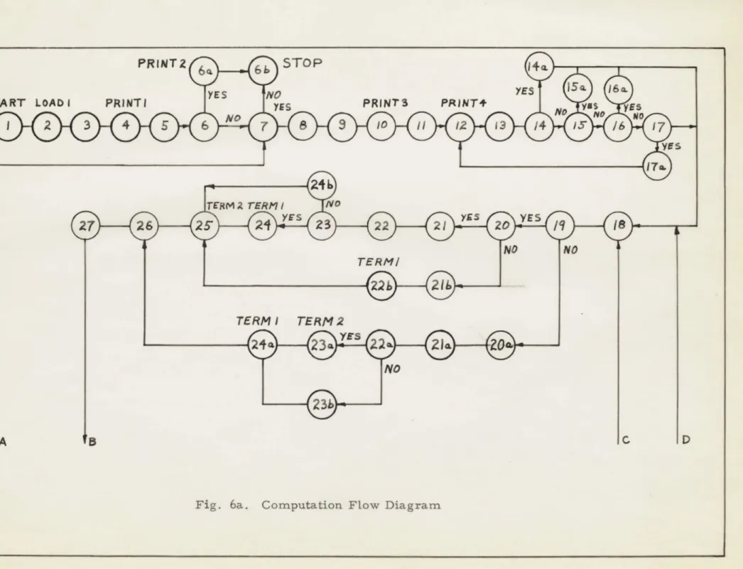
The following symbol table is to be used in conjunction with the Computation Flow Diagram, Fig. 6.
1. Start program.
2. Load 1 - Load data which may vary with each run but not with each pass. These constants are: e , aa, Cd, A9 - A0 (Taylor Series coefficients for the compliance or stiffness curve), max-imum permissible error ratio used in the integration sub-routine, independent variable spacing, u(t = 0), ti (t = 0), i and i , radius
gP
of the gear (R
),
no-load separation coefficient (ce) and profile error (-E).3. Compute s *VPn, s '/Pn and theoretical contact ratio (T. C. R.). 4. Print 1 - Print out values of i , iP, T. C. R.
5. Compute Part 1 of the inverse Y factor constants. 6. Does i = 38?
g
6a. Yes, 1/Y not defined. Print 2 - Print out "Number of teeth = 38". 6b. Stop the computer.
7. Are there any more variables to be loaded for the next pass?
8. Load 2 - Load data which varies with each pass. These constants are
Pe'
Pd
Tc, 2Q, steady state determining reference (Ref. 3),initial number to be placed in Counter R (the counter which determines which tooth-pair is in contact), case number for print out and alpha-numeric plot, format 1 and 2.
9. Initialize program.
10. Print 3 - Print out E, Sie/n, s *d/n' e #d, Tc, 2Q.
11. Compute Em/srt
12. Print 4 - Print out Em/srt
13. Increase Counter R by 1
14. Does Counter R = 1 ? Condition 6. 14a. Yes, set Emi/srt = Em/s rt' 15. Does Counter R = 2 ? Condition 7.
15a. Yes, set Eml/srt = 0 and E m/srt = Em/srt'
16. Does Counter R equal an integer between 2 and 28? 16a. Yes, set E /srt = 0, Eml/srt = 0.
17. Does Counter R equal 28? 17a. Yes, set CounteT R = 0.
18. Compute K n-/K and Kn/K0 as functions of s/Pn. 19. Is (t - T s* /Pn)
' O?
Condition 2.20. Is (T (1 - s Ite'n) -' t) 1
o?
Condition 3. 20a. Compute Asd/srt.21. Compute As e/srt.
2la. Compute (u - Asd/srt - Em2/srt) = term 2.
21b. Set Ase/srt = 0. Condition 3 satisfied. 22. Compute (u -
As/srt
- Emi/srt) = term 1.22a. Is term 2 positive? Condition 4.
22b. Compute Kn/K, (u - Em1/srt) = term 1. 23. Is term 1 positive? Condition 1.
23a. Compute Kn-i/Ko
(u - Asd/srt
-EmZ/rt)
= term 2.23b. Set term 2 = 0. Condition 4 satisfied.
24. Compute Kn/Ko (u - Ase/srt - Emi/srt) = term 1. 24a. Compute Kn/K0 (u - E M/srt) = term 1.
24b. Set term 1 = 0. Condition 1 satisfied. 25. Compute K n-/Ko (u -
E m2/srt)
= term 2.26. Calculate u = 1 - 2p u - n- 1
/K
0 F(u) - Kn/KoF(u).27. Integrate ' to obtain u
-28. Integrate 11 to obtain u.
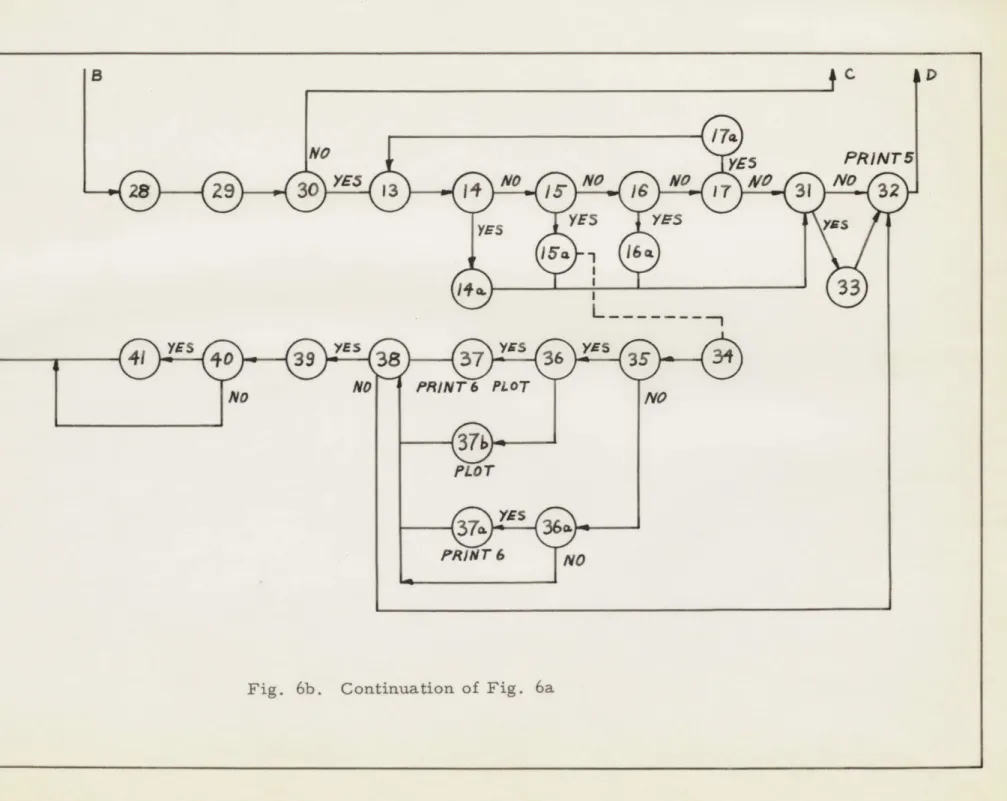
29. Enter up-date sub-routine. 30. Is t r T ? Condition 5.
31. Has the steady state condition been reached? Is I u(t = 0) - u(t= TC)1.4
Ref. 3?
32. Initialize for start of another cycle. Print 5 - Print out u(t=0 ), u(t=0), u(t= T c), u(t= T d
33. Has the error tooth been through the gear mesh? No,, proceed as indicated and calculate until another steady state is reached.
Yes, proceed as indicated for only one cycle. The dotted line from (1-%) to (34) shows the exit of this cycle. This initializes u and A for calculation of the load and stress in the tooth following the error tooth, tooth-pair 2.
34. Compute part 2 of the inverse Y factor and calculate the stress in the tooth following the error tooth.
35. Is sense switch 3 down for plotting on the scope? 36. Is sense switch 2 down for print 6?
36a. Is sense switch 2 down for print 6?
37. Plot (W/Wo)n+1 versus (s/Pndn+i on the scope and print 6. In this case (n+1) stands for tooth-pair 2.
37a. Print 6 - Print out error ratio, load, s/Pn, stress, time and
sr/srt. No plotting.
38. Is this the end of the first pass?
39. Print 7 - Print out actual contact ratio, maximum dynamic stress, maximum dynamic load, number of cycles calculated.
40. Is sense switch 3 down for plotting on scope?
41. Plot grid scales alpha-numeric information on scope for
(W/Wo)n+1 versus (s/Pn)n+1 and then plot the nominal dynamic stress versus (s/Pn)n+I with its grid and scales and alpha-numeric information.
3. 6. Notes on the Program
It has been suggested in Wayne O'Neill's thesis3 that the following values be used when operating the program.
1. The independent variable spacing should be divisable into
Tc from 150 to 250 tirnes. These are the number of corrector integrations which take place. 200 was found to be about optimum.
2. The integration error ratio should be between 0. 01 and 0. 0001.
0. 001 was found to be optimum.
3. Reference 3 for steady-state comparisons should be 0. 0005 but may be increased for low damping ratios in order to de-crease the amount of cycles required to reach steady state. However, a value of 0. 0025 was found to be quite satisfactory.
When Counter R reaches a value of 28, the error tooth is introduced
and Counter R is set to 0.
The initial input to Counter R is from an actual
number in the data deck. This number should be law enough to allow a
steady state condition to be reached on perfect teeth only. Once this
condition is reached, the error tooth is immediately introduced, and the
calculations proceed until the next steady state is reached.
In all calculations and in the analysis, Em/s rt is considered to be
the absolute value of the error ratio. However, a negative value of error
is placed in the data deck so that the print out will emphasize the negative
error.
3. 7. Results
The tabulated results of selected runs are listed in Appendix E.
In Fig. 7, photographs of the plotted results from the cathode-ray
tube are displayed. From top to bottom, plots are shown of Case 2, 3,
and 4 respectively.
The teeth are shown coming into contact in the region
of s/Pn
= -
0. 8.
The tooth comes into contact with the load on its tip and
leaves contact with the load on its base. These plots illustrate the
different effects on the tooth preceding the error tooth, the error tooth,
and the tooth following the error tooth respectively.
In Fig. 8, the effect of a large error ratio is shown.
The load on the
teeth is effectively low, therefore, the manufactured error is predominately
large compared to the deflection of the teeth. The tooth comes into contact
much earlier than it normally would. In effect a positive error may be
consid-ered to be on this tooth.
When contact is made an impact load is placed on the
tooth, which imports a large stress on the tooth.
When larger loads are placed on the teeth as in Case 4, the
manu-factured error ratio is reduced and the initial load is reduced considerably,
as shown in Fig. 7.
It is suggested that this program not be run for manufactured error
ratios less than 0. 500. It was found that below this amount the integration
routine would produce large errors.
3. 8. Summary
A program was written to include the effect of a manufactured error
on the dynamic loads, stress and deflections of gear teeth. The results
obtained compared favorably with the theory of gear teeth action.
65 -0-DYNAMI C 4-0-LOAD 3-20-0 OYNAMI C 1 5 -0!-MOM INA L: I
{
10 -RATIO 2-0 - - -(W/WO) 10--.-5 -1-0 0.0.NORM- POS- A -L-O-A - * S/PN
DAMPING RATIOwO-10
TC=20- 0,BEI -0,SO I-0, IG 27, IP m18
M G MEACHER M11104 SPUR GEAR STUDY C
BENDING STRE 5-0- - -
-SS
0.-L L
I-1.-S -1-0 0.0mNORM- POS- A -L-O-A- 8/PNS
DAMPING RATI =0-10
TC=20 - 0, BEaI -0, BD I-0, IG m27, IP .18
M G MEACHER M 1104 SPUR GEAR STUDY C
--L
-6 - OT 5 - 04-DYNAMI C 4-0-LOAD 3-0-RATIO 2-0-(W/WO) I-0* - - -0-0. -1-5 '-1 -0 0.0
NORM- POS- A -L-O-A - * S/ PN
DAMPING RATI O0 10
TCu20- 0,BEI -0,BD 1 -0, IG s27, IP mIS
I G MEACHER M 1104 SPUR GEAR STUDY C
DYNAMI C LOAD 3-0-- -.-- - --RATIO 2-0- -(W/wO) 1-0- 0.--A -5 -1-0 0.0
NORM- POS- A -L-O-A - a S/PN
DAMPING RATIO.0-O 0
TCu20- 0,BEI -0,BD. I-0,IG =27, IP m1
M G MEACHER M 1104 SPUR GEAR STUDY C
20- 0 DYNAMI C NOMINA L 10-0-BENDING 5-0-STRESS -. 5
-I
F--1-0 0-0
NORM- POS- A -L-O-A- * S/PN
DAMPING RATIOw 0-10
TCw20 - 0, BEI -0, 0. I-0, IG m27, IP m18 M G MEACHER M11104 SPUR GEAR STUDY C
DYNAMI C 15 0 -NOMINAL BENDING 5-0- -STRESS 0 .0 Li- L I -1-5 -1-0 0-0
.NORM- POS- A -L-O-A- * S/PN
DAMPING RATI O.0-10
TC120- 0,BERI 10,B4 I -0,IGE7, IP= M G ME-ACHER M 1 04 SPUR GEAR STUDY C
Fig. 7
b *V
5
-0DYNAMI
C
4 -A
LOAD
RATIO
2
00---4-(W/WO)
-L5
-1-0
0.0
2-030
NORM-
POS-
A-L-0-A
-
S/PN
DAMPING RATI
O0-10
TC.20
-0,BE=2
-67BD
=240, IGu27o IPml
M
G
MEACHER
Ml
104
SPUR GEAR STUDY C
/.- V
DYNAMI C
mnMTMdILBEND
aING
-5 -
. .STRESS
0 -
0-
---1-5
-l-o
0-0
2-03-0
NORM-
POS-
A-L-O-A
-
S/ PN
DAMPING RATI
O0- 10
TC.20
-
0,BE=2 -67,80 m2- 40, IGm27o IPaI
M
G
MEACHER M 1104 SPUR GEAR STUDY C
Fig. 8
15 O
-CHAPTER 4. SUMMARY, CONCLUSIONS AND RECOMMENDATIONS
4. 1. Summary and Conclusions
This thesis has been concerned mainly with the dynamic loads and stresses in gear teeth under various operating conditions.
An analysis of damping was made using a spring-mass and cam model of gear tooth action while single load transfer was taking place.
The maximum dynamic loads on a tooth-pair under idealized conditions for various damping factors were calculated and plotted against the frequency ratio p. The oscillations caused by previous load transfers were assumed to have died out. This was found to be a good assumption when the damping was critical or supercritical or the frequency ratio
P
was small.A digital computer program was extended to include the effects
of a manufactured error on dynamic loads, stress and relative deflections of a set of gear teeth. Print outs and plots of these factors were made against the distance along the line of action of the tooth-pair as it moved through the gear mesh. Comparisons of the dynamic load and stress cycles for the tooth preceding and following the error tooth, and the error tooth, made with those of the static case (Ref. 1), proved to be quite satisfactory.
A large error ratio was investigated which showed how comparatively
-large stresses can be imposed on lightly loaded gears because of early contact.
4. 2. Recommendations
On the basis of this investigation, the following recommendations are made:
1. A short digital computer program should be written to solve
the cumbersome dynamic equation derived in Sec. 2. 2, which describes deflections of single load transfer of a single
tooth-pair for various damping and frequency ratios.
Z. A digital computer program should be written to include
more than one manufactured error. The errors could be programmed so as to vary as the tooth-pairs moves through the mesh. Positive errors and negative errors could be included in the same program.
APPENDIX A. LIST OF[(sr/srt) max
s
st
r
- 1 VERSUS p FOR LARGE
p
Wd Ksrt Wd =
W+ W
(Wj/Ksrt)0
max
0.000040.00076
0.023 0.048 0.127 0.260.36
0.43
0.4540
P
0.950.90
0.700.60
0.40 0.20 0.100.05
0.03APPENDIX B. LIST OF (s/srt) VF s
wd
s t Kart r rWd
W+W
p(W/Ksr
max
0
1.00
0.05
0.926
0.10
0.862
0.20
0.756
0.40
0.602
0.60
0.498
0.70
0.460
0.90
0.394
0.95
0.381
1.00
0.367
1.10
0.351
2.00
0.336
10.00
0.050
4141
APPENDIX C, LISTING OF PROGRAM FORMAT, OPERATION CARDS AND A SAMPLE DATA DECK
RUN 111O4*d60 V.ACHE.I04 SAP M1104*680*GEAR STUDY LST OFF
SMT OFF PRG OFF
INSERT PROGRAM WRITTEN BY AUTHOR, APRIL,1960
LISTED IN APPENDIX D
INSERT THE FOLLOWING SUB-ROUTINES (REF 3) IN ORDER.
1 INTEGRATION ROUTINE WRITTEN BY WAYNE ONEILL-1959 (151 CARDS)
2 UPDATING SUB-ROUTINE WRITTEN BY WAYNE ONEILL-1959 (74 CARDS)
3 GRID PLOTTING ROUTINE FOR COVERING ARBITRARY PORTION OF SCOPE
WRITTEN BY WAYNE ONEILL-1959 (47 CARDS)
4 SCOPE CURVE (POINT) PLOTTING ROUTINE USING ALL OR ARBITRARY PORTION OF SCOPE (MUST BE USED WITH CR4 FOR ARBITRARY GRID) WRITTEN BY WAYNE ONEILL-1959 (102 CARDS)
5 NA.110 WRITL BCD CHARACTERS MODIFIED 8/18/58 BY ONEILL END START
SAMPLE DATA DECK CLR PAK RIP M'1104*880*(LAR*STUDY SWD 2,3 bGN M1104*880*GcAR*STUDY DEC 0.3490b69,l.0,l.157 YEC -5.0484973,-9 .9537395,9.5206339,10.0963819-5.8866139 DL.C 2.2752402,1.b532521,10.768726,0.3826269 17.924958 VEC 1.0#0.U. DEC 1.0 DLC 0.0 DEC 27.0,lb.0 DEC 4.50,0.5432,-O.001-DEL 2.670
,2.45,2e0o0o.2oo.ou
OCT 000021000000 BCD iSE UD BCL 1 05 BCD OTC=2O.0,ouE=2.u/7 ,DL=2.40, =27 , IP= BCD 40AMPINGi -(ATIu=o.10INSER T UAFA CAR06 FOR S.CUN PAS6. KLFLk Tu rI.6
TRA 3,4
INSERT DATA UECK FOR %ECOND RUN. REFER TQ -IG.6 TEk M1104*880* ivEACHER*04
APPENDIX D. PROGRAM LISTING
PL.Vi r 1\ . I\-' I I \'.1 tM .A L . t I L L,.1' \4/~~ , I - I A l I r L.dQ .)9 i i
REM DEFLECTIONS OF GEAR TEETH WITH MANUFACTURED REM' ERikOR jNCLUVLL.
REM WkITTEN bY Mv*e MEACHLk APRIL i bU
REM PAK SYNONYM TAbLE APRIL 25,i900
CUMMON SYN /25
SQRT SYN /356 M SRT I
CQ1 SYN /42-3 UAS+Q1
6IN SYN /424 UAS+CI LOCK SYN /520 UABLCI
SET SYN /1342 iiIF TD T
OVER SYiN /137.: MIFTL)T
WOT SYN /1376 UASTHI
ARCO SYN /21 CLASCI
TAN SYN /2245 LLTANI
LOAD SYN /3534 UADBCL
FINISH SYN /4320 UADBCL
RTX SYN /4321 UATSM2 ORG FINISH TRA END ot<G uVER TRA INTEG-2 ORG /1070
REM LUADS DATA (CUNSTANTS FOR EACH RUN)
START TSX LQAD.4 PZE THETAOAO TRA *+2 TRA END TSX LOAD,4 PZE INTEG+149,0,INTEG+150 TRA *+2 TRA END TSX LOAD,4 PZE U,0,U TRA *+2 TRA END TSX LOAD,4 PZE U1,0,Ul TRA *+2 TRA END TSX LOAD,4 PZE IG,0,IP tRA *+2 TRA END TSX LOAD,4 PZE RG,0,.Eiv TRA *+2 TRA END ToV *+I TOO *+I CLA THETA TSX. COS,4 STO COSTH CLA THETA TSX SIN,4 STO SINTH CLA THETA TSX TAN,4
45
STO REF7 CLA Ul
STO REF8
REM CALCULATION OF S*E/PNS*0/iNANU THLURLTICAL CONTACT RATIO LXA COUN9,1 CLA IG STO I CLA 11 FA) AA FDP Ii FMP FUUR FL)P -II FiAP AA L TL - S I N H L~ SiNTH F PvF SINTH FAL) C U1MM1ivUN TSX SQRT,4 TSX iERROkt4 FSb SINTH STU C 0 UN+1 LLQ TWQ FMP P1 5 T C U!.:1,/ UN L)U CUS TH FMAP CcO~MN STO i:PICU CLA l Fw' 2PICQ FMP CQMMUN+1
STU
SL+2,1
TIX +,1 i TRA +4 CLA IP 6 TO Ii TRA START+42 CLA SE F ) 3Tu TCR TSX Fk4T4,4 P Z.E I j0 0qTcRl\RkLv PAR\T 1 OF SiESS iVERSt:. Y FACTuw- CLUL.TiuNS L)Q TWQ eMP AL) FAU Iu fL) I ST(Q TEPA LO T ENiiP A FMP TEMPA STU COMiHN LDQ COLM-N FPP IG STU TEiMP6 CLA TEvlPA FiL' CL)STH
46
S TO LQ STL CLA FiP STh CLA FAi) CLA FRA . TA U CLAW
C A'S
T R
STO L L) STO TRA CLA FW-F T) P CL A T SX~TQx
T .5X
ST LX)FSB
5ThCLA
STOSTO
F MP LoU/A T SX LL)Q5T L)A
F L ,5T L; TS XPz
TRATX
A TNA TRATSX
PZETRA TSX PZE Ti-iL.TA I iWVTC
O M 1I N THEiv2 INVT TEP2T EM PC
T
EM PC 1G REF 6+ L)NDEF T EPvj P C TEMPC TLM.A QdN L.T
EMP H TAI~N .4 TNETEMPAH
TAN ' TEiPHIN'.VX
T L
MPC
TLIPC T E. iP C T Z rP CL~A~S LAT/\
LCH VAKI
.'4ITH
LACH
ASSTEMPC L P F T +P2 LQLAL) p4 LUAD ,4 N* Ai + 5 LOAO .4 CaNAME50 ,CAOU+
47
TSX TRA TRA TSX P4. L T I A\ T.IN/A TuV TQU SWT TRA W TV CFF LX SXL LXA SXL) LXA SXL T CLA STO CLA 6T LLA 6 TO LLA .5T0 6- T sTO $TO T F S TOa L F P LD. F STU T6X PZEL. LD L STU CLA F0 V ST Lua AM~rL, PU NA
~ii+:)
*+ LND LUjAL) ,'4 * AD,4 *+.1 a 3 CQUNb6.1. CuUNu, 1 CoUUNC, I Co ,-J.4. 00UNO couUl. Co) U P L -LuUPO+i-7 TEMPE L )LPC+i 7 R L Fl NO H LOU -L u t-I LYOPD-4. L KW t PC 6LL b EbE
0 F TF 4suu
) IN F *ri 0 1 NV.%~F
I co /,.>)48
F L P FLA F rvi P F L) S T CLA FuP STQ T6X LMQ FP STO RE STZ STZ CLA STU TRA CLA ST L TSX PZE CLA STO CLA 5OK T X
TPL
STZ TA CLA S S TOPLE
STU CLA ST TRAN CLA STNZ 10IG
C
aL)
CL L6Lo( 9 U 9 L- , E Ivi S RIC'JTIALIL TOOTH CUNT
EMSR 2 EIASR2 o A 6 L OLo P Y A ,A 6 N X/ F40T,4 I1)-NIILZ U t-A TH UN Ul EMS1 P L NM i3. T + 7 CuN TCL k i 0I TERMI EMSR2 *-+ 13