Science Arts & Métiers (SAM)
is an open access repository that collects the work of Arts et Métiers Institute of Technology researchers and makes it freely available over the web where possible.
This is an author-deposited version published in: https://sam.ensam.eu Handle ID: .http://hdl.handle.net/10985/10128
To cite this version :
Adam MORAWIEC, Raphaël PESCI, Jean-Sébastien LECOMTE - Semiautomatic determination of orientations and elastic strain from Kossel microdiffraction - In: The 15th International
Conference on the Texture of Materials, Etats-Unis, 2008-06 - Ceramic Transactions - 2008
Any correspondence concerning this service should be sent to the repository Administrator : [email protected]
SEMIAUTOMATIC DETERMINATION OF ORIENTATIONS AND ELASTIC STRAIN FROM KOSSEL MICRODIFFRACTION
Adam Morawiec
Institute of Metallurgy and Materials Science, Polish Academy of Sciences Reymonta 25
PL-30-059 Kraków, Poland Raphaël Pesci
LPMM UMR CNRS 7554, Ecole Nationale Supérieure d'Arts et Métiers 4 rue Augustin Fresnel
57078 Metz, Cedex 03 France
Jean-Sebastien Lecomte
Laboratoire d’Etude des Textures et Application aux Materiaux, Institut Superieur de Genie Mecanique et Productique, Université Paul Verlaine - Metz, UMR CNRS 7078,
Ile du Saulcy, Metz, 57045 Metz, Cedex 1 France
ABSTRACT
The technique of divergent beam X-ray (Kossel) diffraction is being used for determination of local lattice orientations and lattice distortions (elastic strains). The Kossel patterns are recorded in a scanning electron microscope using a digital camera. The advancement in automation of the of the system relies on computerized interpretation of the Kossel patterns. The paper reports on a package of computer programs facilitating computation of orientations and the strain tensors from the geometry of Kossel conics. The orientation and strain parameters are determined based on conics marked manually on experimental patterns; these marked conics are matched with simulated patterns. The program can simultaneously match multiple patterns originating from the same sample location. The software does not require special orientations, and it is not limited to any particular material. Tests on simulated patterns have been used to confirm the internal consistency of the program. These tests also indicate the achievable accuracy; with the current approach, it is estimated to be about 3×10⁻⁴.
INTRODUCTION
There is a considerable interest in examination of polycrystalline materials at a local scale. In particular, there is a large demand for high resolution data on lattice orientations and lattice distortions (elastic strains). These characteristics are important in analysis of a vast range of crystalline materials, from simple metallic samples, through alloys and intermetallics, ceramics and composites, to sophisticated electronic devices. Most of such data are obtained by microdiffraction. In particular, large sets of local orientations are measured using the EBSD technique. There are also efforts to use EBSD for strain determination. However, more suitable
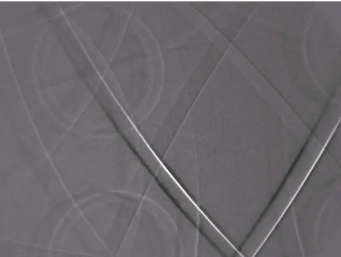
Figure 1. Kossel diffraction pattern of CuAlBe shape memory alloy.
for this purpose is the technique of divergent beam X-ray diffraction. Differently than EBSD – it can provide (absolute) lattice parameters.
There is a variety of experimental set-ups and pattern acquisition geometries utilizing divergent X-rays. In particular, in the conventional Kossel diffraction, divergent X-rays are excited by the presence of fluorescing atoms within the crystal [1]. With a planar detector, their diffraction leads to a (Kossel) pattern of intersecting conic sections or fragments of such conics. See Fig. 1. An external divergent source makes it possible to study non-fluorescing crystals [2]. A sample can be coated with a fluorescing metallic foil as the source of divergent X-rays. Kossel patterns are also acquired using synchrotron radiation [3-5] but this approach is restricted by limited access to particle accelerators.
The Kossel technique is suitable for orienting a crystal, refinement of lattice parameters and for estimation of structure factors. These applications were advanced in the sixties with the use of electron probe microanalyzers (see, e.g., [6,7]). Nowadays, with the progress in digital cameras and the possibility of direct computer analysis of diffraction patterns, the use of the Kossel technique for strain determination is being considered again. In particular, the combination of scanning electron microscopy equipped with CCD cameras and tensile loading devices seems to be an attractive tool for in situ investigation of deformation mechanisms [8,9].
Improvements in the Kossel technique are directed towards getting more reliable results faster and with less effort based on programmed interpretation of diffraction patterns by personal computers. In the case of orientations (which are necessary for the determination of strain), the key point is just the automation of measurements. The situation with strain is different: since the interest is in distortions of the magnitude < 0.001, getting reliable values of strain tensor components is difficult even in the case of good quality patterns. Moreover, one faces the non-trivial problem of computing the tensor from the geometry of Kossel conics. Getting it by
“manual” matching of simulated and experimental patterns by trial-and-error is not possible because of the large number of free parameters.
To address these issues, dedicated software has been developed. We describe a package of computer programs facilitating the determination of orientations and strains based on the Kossel diffraction patterns. The strain or lattice parameters are semi-automatically determined by matching geometric features of experimental and simulated patterns. To ensure good reliability of results, the program is capable of simultaneous matching of multiple patterns originating from the same sample location. User-specified strain components, sample-to-detector distances and locations of pattern centers can be fitted. The software is not limited to any particular material or structure. Operation of the package is controlled via a Windows user interface.
COMPUTER BASED ANALYSIS OF KOSSEL PATTERNS
There are numerous programs for simulation of Kossel patterns (e.g., [10, 11]). They are usually based on the geometric diffraction theory [12] with kinematically calculated intensities used only to decide about the presence or absence of a given reflection. With λ denoting the radiation wavelength, the wave-vector k of a reflected beam satisfies k · k = 1/λ2 and the ‘‘K-line equation’’
2g · k = g · g , (1)
where g is the reciprocal lattice vector corresponding to the line. Kossel conics are located at intersections of directions of the wave-vectors with a detector.
The (inverse) problem of orientation and strain determination form Kossel patterns is more involved. Numerous methods for solving these issues have been devised. (These older methods were reviewed by Gielen et al. [13] and Tixier and Wache [14].) However, most of these methods are not applicable for our purposes because they rely on particular orientations and/or on some specific features of Kossel patterns (e.g., presence of “lenses” or particular “lenses”). Modern approach is to consider the pattern as a whole, and to match all accessible features of experimental and simulated patterns.
Also computer programs for orientation and strain determination have been created in the past [15-18]. The older programs are not suitable in contemporary environment. They are numerical in nature, whereas nowadays, options allowing for analysis of digitally recorded patterns directly on a computer screen are indispensable [19,20].
KSLStrain SOFTWARE PACKAGE
We created a new package of computer programs for analysis of Kossel patterns. It is based on a software for refinement of lattice parameters from convergent beam electron diffraction (CBED) patterns [21]. The package (called KSLStrain) is capable of geometric simulation of patterns, orientation determination and lattice parameter refinement (or strain determination). Also the pattern center and sample-to-detector distance are fine-tuned.
Orientation determination and the refinement of lattice parameters, pattern center location and sample-to-detector distance are based on manually marked conics. The fitting of patterns for the refinement of lattice parameters can be simultaneously performed for multiple patterns. The software does not require special orientations of the sample, and it is not limited to any particular material.
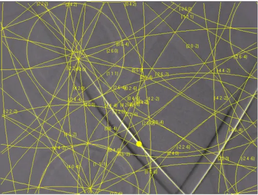
Figure 2. KSLStrain interface and CuAlBe pattern with some conics marked.
Figure 3. Experimental CuAlBe pattern with and matching simulated diagram obtained based on marking points shown in Fig.2.
As for limitations of KSLStrain, we do not make any use of the fine structure of the Kossel reflections. All dynamical effects of diffraction are ignored. The refraction (as the beam comes from a crystal into the vacuum) is disregarded. Moreover, it is assumed that there are no distortions of the recording medium (device).
Method of operation
The operation of KSLStrain starts with loading (up to ten) Kossel patterns of arbitrary dimensions. Then conics on the patters must be marked using a computer mouse (by clicking at a number of points per one conic section); see Fig. 2. Based on the locations of the marking points, crystal orientations are calculated. They are determined with the help of suitably adapted KiKoCh - an engine for resolving K-line diffraction patterns (routinely used for orientation determination from Kikuchi electron diffraction patterns [22, 23]). The program calculates the orientation parameters by matching the reciprocal lattice vectors obtained from the marked points of the experimental diffraction pattern to the crystallographic reciprocal lattice to obtained from the crystallographic data for the investigated material. We refer to [24] for a detailed description of the program.
Crucial for the strain determination are values of the radiation wavelength, the sample-to-detector distance and the location of the pattern center. Since the wavelength is known with relatively high accuracy, the user provided data are assumed to be exact. As for the pattern center and the sample-to-detector distance, the situation is different. In normal experimental conditions, the estimated values of these parameters are not sufficiently accurate for reliable strain determination. Getting better estimates based on direct measurements requires much effort. Therefore, an additional procedure is used to fit these parameters (with fixed reference values of lattice parameters). The fitting is based on the geometry of the pattern; the sample-to-detector distance is linked directly to pattern magnification, and the pattern center is placed at the intersection of major axes of the conics.
Once the orientation is determined and specimen-to-detector distance and pattern center are tuned, one can proceed with the refinement of lattice parameters. Methods analogous to those used in the case of CBED patterns can be applied (e.g., fitting distances between intersections of conics or their ratios). The current version of KSLStrain uses the so-called ‘‘K-line equation based scheme’’ or KLEBS. [25]. Briefly, it is an optimization procedure matching Kossel conics in experimental patterns to corresponding conics in simulated patterns. The procedure uses an objective function based directly on the underlying algebraic equation (1) of the Kossel conics. Strain is determined by finding the location of a global minimum of the function (of strain tensor components)
ψ = S (2k · g − g · g)2; (2)
the summation is over all patterns and all points marking the conics. Also at this stage, together with the strain components, the crystal orientation parameters, pattern center coordinates and the specimen-to-detector distance are fitted. Visual example of a result of such procedure is shown in Fig. 3.
Numerical tests on simulated patterns
Tests on simulated patterns (for which the correct solutions are known) are the best way to check the internal consistency of the software. They also give the level of the best achievable accuracy of strain determination. We performed a number of such tests. The results depend on
the number of patterns used, the choice of the patterns, the number of free strain tensor components, the ratio of specimen-to-detector distance to detector diameter and other parameters. With the current approach, we roughly estimate the achievable accuracy to be about 300 µstrain. For example, a test for three simulated patterns of Cu with the ratio of specimen-to detector distance to detector diameter of ~0.4 gave results for six free strain tensor components within 2×10⁻⁴ from their correct values.
CONCLUSION
There is a new interest in the Kossel technique used in combination of scanning electron microscopy with digital recording of patterns. The technique is suitable for local orientation and elastic strain determination (refinement of lattice parameters). The main challenge today is to limit human involvement and to endow the strain determination system with as much automation as possible.
We report on a new software for semi-automatic analysis of Kossel patterns for determination of orientations and strain. Based on manually marked points of Kossel conics, the program KSLStrain is capable of automatic tuning of pattern center coordinates and sample-to-detector distance. Moreover, it automatically determines the orientation the crystal. The same points are used for lattice parameter refinement. The fitting of lattice parameters can be carried out simultaneously for multiple patterns.
The package is a step towards even more sophisticated strain measurement schemes. With automatic analysis of diffraction patterns, one may envision setting-up a strain mapping system*. This can be already done in a manual mode. For fully computerized strain mapping, reliable routines for accurate detection of the Kossel conics would be needed.
FOOTNOTES
* It is worth reminding the reader that the first color orientation maps (analogous to now ubiquitous EBSD maps) have been created using the transmission Kossel technique [26, 27]. REFERENCES
[1] W. Kossel, V. Loeck and H. Voges, Die Richtungsverteilung der in einem Kristall entstandenen charakteristischen Röntgenstrahlung, Z.Phys. 94, 139–144 (1935).
[2] K. Lonsdale, Divergent-Beam X-ray Photography of Crystals, Philos. Trans. R. Soc. A 240, 219–250 (1947).
[3] H.J. Ullrich, M. Schlaubitz, F. Friedel, T. Spann, J. Bauch, T. Wroblewski, S. Garbe, G. Gaul, A. Knöchel, F. Lechtenberg, E. Rossmanith, G. Kumpat and G. Ulrich, Excitation of Kossel Patterns by Synchrotron Radiation, Nucl. Instrum. Methods A 349, 269–273 (1994). [4] Ch. Schetelich, S. Weber, V. Geist, M. Schlaubitz, H.J. Ullrich, S. Kek and H.G. Krane,
Recording of Kossel Patterns Using Monochromatic Synchrotron Radiation, Nucl. Instrum. Methods B 103, 236–242 (1995).
[5] A.M. Glazer, S.P. Collins, D. Zekria, J.Liu and M. Golshan, Observation of Divergent-Beam X-Ray Diffraction from a Crystal of Diamond Using Synchrotron Radiation, J.Synchrotron Rad. 11, 187–189 (2004).
[6] D.L. Vieth and H. Yakowitz, Design Considerations for a Kossel Microdiffraction Camera, Rev. Sci. Instrum. 37, 206–209 (1966).
[7] D.L. Vieth and H. Yakowitz, Tensile Loading Device for Kossel Microdiffraction and Metallography, Rev. Sci. Instrum. 39, 1929–1931 (1968).
[8] E. Langer, S. Daebritz, C. Schurig and W. Hauffe, Lattice Constant Determination from Kossel Patterns Observed by CCD Camera, Appl. Surf. Sci. 179, 45–48 (2001).
[9] S. Berveiller, P. Dubos, K. Inal, A. Eberhardt and E. Patoor, Inter- and Intra-granular Strain Analysis by Microdiffraction Kossel, Mater. Sci. Forum 490–491, 159–165 (2005).
[10] E. Langer, R. Kurt, S. Daebritz, KOPSKO: a Computer Program for Generation of Kossel and Pseudo Kossel Diffraction Patterns, Cryst. Res. Technol. 34, 801–816 (1999).
[11] S. Weber, KOQUA2.0: a Program for Simulating Divergent-Beam Diffraction Patterns for Crystals and Quasicrystals, J.Appl.Cryst. 30, 85–86 (1997).
See also http://www.jcrystal.com/products/kossel/index.htm
[12] P.P. Ewald, Introduction to the Dynamical Theory of X-ray Diffraction, Acta Cryst. A 25, 103–108 (1969).
[13] P. Gielen, H. Yakowitz, D. Ganow and R.E. Ogilvie, Evaluation of Kossel Microdiffraction Procedures: the Cubic Case, J. Appl. Phys. 36, 773–782 (1965).
[14] R. Tixier and C. Wache, Kossel Patterns, J. Appl. Cryst. 3, 466–485 (1970).
[15] W.G. Morris, Crystal Orientation and Lattice Parameters from Kossel Lines, J. Appl. Phys. 39, 1813–1823 (1968).
[16] B.H. Heise, Precision Determination of the Lattice Constant by the Kossel Line Technique, J.Appl.Phys. 37, 4560–4571 (1966).
[17] P. Pietrokowsky, Lattice Parameter of alpha Iron by Divergent Beam Diffraction, J.Appl.Phys. 33, 938–941 (1962).
[18] D.G. Fisher and N. Harris, A Computer Program for the Calculation of Lattice Spacings from Kossel Diffraction Patterns, J. Appl. Cryst. 3, 305–313 (1970).
[19] J. Bauch, St. Wege, M. Böhling, and H.-J. Ullrich, Improved Approaches to the Determination of Residual Stresses in Micro Regions with the KOSSEL and the XRT Technique, Cryst. Res. Technol. 39, 623–633 (2004).
[20] E. Langer, S. Däbritz, C. Schurig and W. Hauffe, Lattice Constant Determination from Kossel Patterns Observed by CCD Camera, Appl. Surf. Sci. 179, 45–48 (2001).
[21] A. Morawiec, A Program for Refinement of Lattice Parameters Based on Multiple Convergent Beam Electron Diffraction Patterns, J. Appl. Cryst. 40, 618–622 (2007).
[22] A. Morawiec, J.J. Fundenberger, E. Bouzy and J.S. Lecomte, EP - a Program for Determination of Crystallite Orientations from TEM Kikuchi and CBED Diffraction Patterns, J. Appl. Cryst. 35, 287 (2002).
[23] J.-J. Fundenberger, A. Morawiec, E. Bouzy and J.S. Lecomte, Polycrystal Orientation Maps from TEM, Ultramicroscopy 96, 127–137 (2003).
[24] A. Morawiec, Automatic Orientation Determination from Kikuchi Patterns, J. Appl. Cryst. 32, 788–798 (1999).
[25] A. Morawiec, An Algorithm for Refinement of Lattice Parameters Using CBED Patterns, Ultramicroscopy 107, 390–395 (2007).
[26] Y. Inokuti, Y. Shimizu and H. Shimanaka, Crystallographic Orientation Determination of Small Areas in Grain Oriented Silicon Steel by Transmission Kossel Technique, Kawasaki Steel Giho 12, 89-98 (1980).
[27] Y. Inokuti, C. Maeda and Y. Ito, Transmission Kossel Study of the Formation of (110)[001] Grains after an Intermediate Annealing of Grain Oriented Silicon Steel Containing a Small Amount of Mo, Metall. Trans. A 16, 1613-1623 (1985).