En cotutelle
T
HEORETICAL
I
NVESTIGATION AND
N
ON
-
LINEAR
F
INITE
E
LEMENT
A
NALYSIS TOWARD
D
ESIGNING
R
EINFORCED
C
ONCRETE
F
ILLED
FRP-T
UBE
C
OLUMNS
É
TUDE
T
HÉORIQUE
E
T
A
NALYSE
N
ON
-L
INIÈRE
P
AR
É
LÉMENTS
F
INIS
P
OUR
L
A
C
ONCEPTION
D
E
C
OLONNES
E
N
B
ÉTON
A
RMÉ
C
ONFINÉES
À
L
’
AIDE
D
E
T
UBE
E
N
P
RF
Thèse de doctorat Spécialité : génie civil
Maha Mohamed Hussein Mohamed Abdallah
A dissertation submitted in partial fulfilment
of the requirements for the degree of
Doctor of Philosophy
(Civil Engineering)
Jury:
1. Prof. Radhoune Masmoudi (Directeur de Recherche-Université de Sherbrooke) 2. Prof. Ahmed Moussa (Co-directeur de Recherche- Université de Helwan) 3. Prof. Hamdy Mohamed (Co-directeur de Recherche- Université de Helwan) 4. Prof. Arezki Tagnit-Hamou (Rapporteur-Évaluateur-Université de Sherbrooke) 5. Prof. Khaled E.Galal (Évaluateur--Université de Concordia)
i
A
BSTRACT
Fibre-reinforced polymer (FRP) composite materials have been extensively used in the field of civil engineering construction, especially in structures subjected to corrosive environments. One of the innovative techniques for using FRP is the FRP tubes which can be used as structurally integrated stay-in-place forms for concrete members as columns, piles, piers and beams.
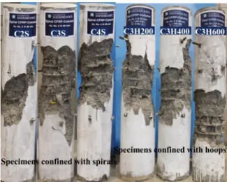
Extensive research was carried out to understand the behavior of concrete-filled FRP tube (CFFT) columns under axial loading, but comparatively limited research was conducted on the reinforced CFFT columns under eccentric loading. This thesis aims to provide experimental work as well as extensive theoretical analysis and design recommendations of circular CFFT columns reinforced with steel bars or carbon fibre reinforced polymer (CFRP) bars. CFFT columns were tested under monotonic loading with different levels of eccentricity. Test variables included the eccentricity to diameter ratio (e/D) and reinforcement type (CFRP bars vs steel). All specimens measured 152 mm in diameter and 912 mm height. The tubes used is basically filament wound glass fibre reinforced polymer tube (GFRP) with a core diameter of 152 mm and a wall thickness of 2.65 mm (6 layers). The fibre orientation of the tube was mainly in the hoop direction (± 60 degree with respect to the longitudinal axis). Six reinforcing bars (steel or CFRP) were used and distributed uniformly in each specimen. Test results indicate that specimens with CFRP reinforcement (CFRP-CFFT) behaved very similar to their steel counterparts with nearly the same nominal axial forces. Failure of CFFT columns was dominant by overall instability of the columns along with the combination of tensile rupture of FRP tube and CFRP bars or steel yielding. Experimental strain results revealed that the CFRP bars developed high strains on the compression and tension sides, thus CFRP bars contribution was considered effective in resisting tensile and compressive stresses. In addition, the maximum tensile strain reached in the GFRP tube was considered low when compared to the GFRP hoop strain, thus, it was concluded that the confinement induced by the GFRP tube become less significant in the case of eccentrically loaded column. Experimental axial-moment interaction diagrams were presented to indicate the failure envelope of steel and CFRP reinforced CFFT columns. Moreover, a theoretical model was developed to indicate the axial-moment capacities of steel and CFRP reinforced CFFT columns using plane sectional analysis
layer by layer approach was developed to predict the moment-curvature response for steel and CFRP- reinforced CFFT columns. These results were compared to the experimental moment-curvature curves and it was clear that regardless of the type of reinforcement and value of eccentricity, all specimens exhibit non-linear moment curvature behavior.
An extensive study was conducted on the effective flexural stiffness of CFFT columns, on the basis of experimental parametric study and theoretical simulation. Proposed equations were developed and validated against the experimental results to represent the stiffness of steel and CFRP- CFFT circular columns at service and ultimate loads.
Moreover, a theoretical investigation was conducted to propose a more precise formula for the critical slenderness limit to control the buckling mode of failure of FRP-reinforced CFFT columns. It was found that the critical slenderness limit of 14 could be used as a safe value for practical design purposes. The theoretical analysis in this research was carried out using excel. Finally, a nonlinear finite element model using ABAQUS software was presented based on Lam and Teng confined concrete model considering material and geometric nonlinearities of CFFT columns. This model aims to provide insight on the structure behavior and failure mechanism of CFFT columns.
Keywords: Concrete, FRP bars, FRP tubes, columns, eccentricity, failure, sectional analysis, curvature, stiffness, buckling, finite element analysis.
iii
R
ÉSUMÉ
Les matériaux composites en polymères renforcés de fibres (PRF) ont été utilisés largement dans le domaine de la construction en génie civil, particulièrement pour les structures exposées à un environnement corrosif. L’utilisation des tubes en polymères renforcés de fibres (PRF) est une technique innovante pour les éléments de structures en béton armé tels que les colonnes, les piliers et les poutres, où les tubes en PRF sont utilisés comme coffrage permanent.
Des recherches précédentes ont été effectuées pour comprendre le comportement des colonnes (CFFT) sous chargement axial mais il existe très peu de données concernant le comportement des colonnes en béton armé et renforcées de tubes en PRF sous chargement excentrique. Cette thèse présente des données expérimentales, une analyse théorique approfondie et des recommandations de conception pour colonnes cylindriques CFFT armées de barres d'acier ou de barres en polymères renforcés de fibres de carbone (CFRP). Les colonnes CFFT ont été testées sous un chargement monotone avec différents niveaux d'excentricité. Le rapport d’excentricité (e / D), et le type d’armature longitudinale (barre CFRP versus barre en acier) sont considérés comme des variables pour tous les essais effectués. Le diamètre et la hauteur de chaque spécimen sont égaux à 152mm, 912mm respectivement. L’angle d’orientation des fibres du tube a été principalement dans la direction circonférentielle (± 60 degrés par rapport à l'axe longitudinal). Six barres d'armature (acier ou CFRP) ont été utilisées et sont réparties uniformément dans chaque échantillon.
Les résultats de cette étude ont révélé que les échantillons armées avec des barres en PRFC se comportent de manière très similaire aux échantillons armés de barres en acier et atteignent, à toute fin pratique, les mêmes résistances axiales. Le mode de rupture des échantillons de CFFT a été dominé par l'instabilité globale des colonnes ainsi que par la combinaison de la rupture en traction du tube en PRF et des barres en PRFC ou en acier.
Les résultats expérimentaux de la déformation ont montré que les barres de PRFC développent des déformations élevées sur les côtés de compression (Valeur maximale en compression -5000 μɛ) et de traction (Valeur maximale en traction 10,400 μɛ), ainsi les barres PRFC résistent mieux aux contraintes de la traction et de la compression.
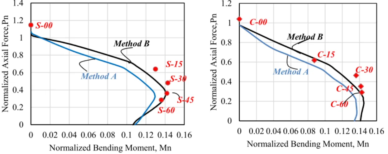
considérée comme étant une contrainte faible par rapport à celle enregistrée dans la direction circonférentielle du tube en PRF. D’après les résultats expérimentaux enregistrés, le confinement induit par le tube en PRF est moins important dans le cas d’une colonne sous charge excentrée. Des diagrammes expérimentaux d'interaction charge axiale-moment ont été présentés pour déterminer l'enveloppe de rupture des échantillons CFFT armées de barres en acier ou de barres en PRFC.
De plus, une analyse théorique a été développée pour calculer les résistances des colonnes CFFT soumises à un chargement excentrique. Une comparaison avec les résultats expérimentaux a été effectuée. Aussi, une analyse théorique basée sur l'approche couche par couche a été développée pour prédire la réponse moment versus courbure des colonnes CFFT armées de barres en acier ou de barres en PRFC. Ces résultats ont été comparés aux résultats expérimentaux des courbes de moment-courbure. Il a été conclu que quelques soient le type d’armature (acier versus PRFC) pour les colonnes CFFT et la valeur de l’excentricité, le comportement moment-courbure de tous les échantillons est non linéaire.
Par ailleurs, une étude approfondie a été effectuée sur la rigidité en flexion (EI) effective des colonnes CFFT. Cette étude est basée sur une étude paramétrique expérimentale et une simulation théorique. Les équations proposées ont été développées et validées par rapport aux résultats expérimentaux afin de représenter la rigidité des colonnes CFFT armées de barres en acier ou de barres en FRPC. Ces équations sont établies pour deux limites : les états-limites de service et les états-états-limites ultimes.
Aussi, une formule précise pour la prédiction du taux d’élancement pour contrôler le mode de rupture par flambement pour les colonnes CFFT armées de barres en PRFC a été proposée. Il a été établi qu’un taux d’élancement égal à 14 présente une valeur sécuritaire pour la conception de ces colonnes CFFT en béton armé.
Enfin, un modèle non-linéaire par éléments finis utilisant le logiciel ABAQUS a été développé et présenté sur la base d'un modèle de béton confiné « Lam et Teng» prenant en considération la non- linéarité matérielle et géométrique des colonnes CFFT. Ce modèle permet de fournir un aperçu sur le comportement de la structure et du mécanisme de rupture des colonnes CFFT.
v Mots clés: Béton, barres en PRF, tubes en PRF, colonnes, excentricité, moment-courbure, rupture, analyse par section, bloc de contrainte, courbure, rigidité, flambement, analyse par éléments finis.
vii
B
IBLIOGRAPHY
During this research work, the candidate has participated in the following publications;
Journal Papers
Abdallah, M.H., Mohamed, H.M., Masmoudi, R., and Moussa, A “Analytical Modeling of Moment-Curvature Behavior of Steel and CFRP RC Circular Columns Confined with GFRP Tubes . ” Journal of composite Structures, Elsevier, 189 (2018), 473-487.
Abdallah, M.H., Mohamed, H.M., Masmoudi, R., and Moussa, A “Experimental and Theoretical Development of Effective Flexural Stiffness for Concrete-Filled FRP Tube Columns” Journal of Engineering Structures, Elsevier. (Submitted in Jan. 2018, Under review)
Abdallah, M.H., Mohamed, H.M. and Masmoudi, R “Experimental Assessment and Theoretical Evaluation of Axial Behavior of Short and Slender CFFT Columns Reinforced with Steel and CFRP Bars” Journal of Construction and Building
Materials, 181 (2018) 535–550.
Abdallah, M.H., Shazly,M., Mohamed, H.M., Masmoudi, R., and Moussa, A “Nonlinearfinite element analysis of short and long reinforced concrete columns confined with GFRP tubes . ” Journal of Reinforced Plastics and Composites, 13(2017), 972 – 987.
Refereed Conference Publications
Abdallah, M.H., Shazly, M., Mohamed, H.M., Moussa, A., and Masmoudi, R. [2016] “Numerical Analysis of Concrete-Filled Fiber Reinforced Polymer Tube Columns.”
The ninth Alexandria international conference on Structural and Geotechnical Engineering, Alexandria, Egypt, December 19-21, pp.796-803
Mohamed, H.M., Abdallah, M.H., and Masmoudi, R. [2016] “Experimental Behavior of Steel and Carbon FRP-Confined Concrete Columns under Eccentric Loads.” The
ninth Alexandria international conference on Structural and Geotechnical Engineering, Alexandria, Egypt, December 19-21, pp.804-811
Abdallah, M.H., Mohamed, H.M., Masmoudi,R., and Moussa, A “Moment-Curvature Characteristics for Steel and CFRP Reinforced CFFT columns: Experimental and Theoretical Study” [Submitted Dec. 2017], 9th International Conference
Fibre-Reinforced Polymer (FRP) Composites in Civil Engineering (CICE 2018) ,Paris,
France on 17-19 July 2018.
Abdallah, M.H., Mohamed, H.M., Masmoudi, R., and Moussa, A” Non-Linear Effective Flexural Stiffness for Slender Steel CFFT Columns” [Submitted Dec.2017],
Quebec, Canada, July 31 – August 3, 2018.
Masmoudi, R., Mohamed, H.M., Abdallah , M.H. “ Behavior of Concentric and Eccentric CFFT Columns” 1st International Conference on Vulnerability and
ix
Dedication
ACKNOWLEDGEMENT
All praise be to almighty ALLAH.
Words cannot express the author sincere gratitude and appreciation to her supervisor Professor Radhouane Masmoudi (University Sherbrooke) and her co-supervisors Professor Ahmed Moussa and Professor Hamdy Mohamed (Helwan University-Egypt) for their guidance, support, inspiration and encouragement throughout this research program.
Sincere words of thanks must also go to Professor Arezki Tagnit-Hamou and Professor Khaled E. Galal for their valuable suggestions and critical comments that helped in advancing the research.
The author wishes to thank Dr Mostafa Shazly (Director of Center of Advanced Materials, The British University in Egypt) for his guidance and support during the finite element phase of this research program.
The author also expresses his thanks and deep appreciation to her mother, brother and sisters for their endless love and support.
Finally, the author wishes to extend her deep love and appreciation to her husband Yasser and her son Younes for their continuous devotion, kindness and support in every step throughout this research.
xi
C
ONTENTS
ABSTRACT I CONTENTS XI LIST OF FIGURES ... XV LIST OF TABLES ... 18 CHAPTER 1 INTRODUCTION ... 1 1.1 General Background 1 1.2 Research Objectives 2 1.3 Methodology 3 1.4 Thesis organization 5CHAPTER 2 LITERATURE REVIEW ... 7
2.1 Background on Materials 7 2.1.1 FRP COMPOSITE MATERIALS 7 2.2 Behavior of CFFTs 8 2.2.1 Axial Behavior of CFFT 8 2.2.2 Flexure Behavior of CFFT 11 2.3 Field Applications of CFFT 17
2.4 Behavior of RC Columns Reinforced with FRP Bars 19
2.4.1 Columns Behavior under Concentric Loading 19
2.4.2 Columns Behavior under Eccentric Loading 27
2.5 Confinement Models 31
2.6 Finite Element Modelling 37
2.7 Summery 42
CHAPTER 3 ANALYTICAL MODELING OF MOMENT-CURVATURE BEHAVIOR AND P-M DIAGRAM OF STEEL AND CFRP RC CIRCULAR COLUMNS CONFINED WITH GFRP TUBES43
3.1 Introduction 44
3.2 Research Significance 46
3.3 Experimental Program 46
3.3.1 Materials 46
3.3.2 Test Specimens 48
3.3.3 Instrumentation and Test Setup 49
3.4 Observed Behavior and Test Results 52
3.4.1 Test Results and Discussion 52
٣٫٤٫٤ Ultimate Load Carrying Capacity and Eccentricity Effect 56
3.4.5 Steel and CFRP Bars Strain Profiles 57
3.4.6 GFRP Tube Strain Profiles 59
3.5 Experimental and Theoretical models of (P-M) Interaction Diagrams 60
3.5.1 Experimental (P-M) Interaction Diagrams 60
3.5.2 Theoretical Modeling 62
3.5.3 Detailed Proposed Sectional Analysis Methods 65
3.5.1 Comparison between Experimental and Theoretical P-M Interaction Diagrams 70
3.6 Experimental and Analytical moment-curvature for steel and CFRP reinforced CFFT
columns 71
3.6.1 Moment-Curvature Analytical Model 72
3.7 Parametric Investigation 77
3.8 Conclusions 80
CHAPTER 4 EXPERIMENTAL AND THEORETICAL DEVELOPMENT OF EFFECTIVE FLEXURAL STIFFNESS FOR CONCRETE-FILLED FRP TUBE COLUMNS ... 84
4.1 Introduction 85
4.2 Research Objective 88
4.3 Review for Current Codes and Past Studies on Stiffness Expressions 88
4.4 Experimental Data Base 91
4.5 Theoretical Stiffness Equation 94
4.5.1 Development of Theoretical Computational Method for Bending Moment
Resistances Considering Second Order Effects 96
٤٫٥٫٢ Parameters Used for Simulation of Theoretical Stiffness of CFFT Columns
100
4.5.3 Comparison between available effective EIe equation and theoretical EIth
values 102
4.5.4 Requirements for Developing of Effective Flexural Stiffness EIe Equation
103
4.5.5 Variables Used for Proposed EIe Equation 103
4.5.6 Analysis of the Theoretical Stiffness Data using the Multiple Regression Method 105
4.5.7 Proposed EIe Equation for Steel and FRP Reinforced CFFT Columns 106
4.6 Comparison of Proposed EIe Equations and the Experimental Data at Service and
Ultimate Loads 109
xiii CHAPTER 5 MODELLING OF BUCKLING INSTABILITY IN FRP REINFORCED CFFT COLUMNS 118
5.1 Introduction 118
5.2 Overview of Past Experimental Work 119
5.3 Theoretical Investigation of Instability Buckling Behavior and Slenderness Effect of
FRP Reinforced CFFT Columns 121
5.3.1 Reduced and Tangent Modulus Loads 124
5.4 Comparison between Experimental Values and Design Equations 127
5.5 FRP CFFT Columns Strength Curve 128
5.6 Parametric Study 129
5.7 Conclusions 133
CHAPTER 6 NNONLINEAR FINITE ELEMENT ANALYSIS OF SHORT AND LONG REINFORCED CONCRETE COLUMNS CONFINED WITH GFRP TUBES ... 135
6.1 Introduction 136
6.2 Numerical Modelling and Simulation 138
6.2.1 Modelling Approach 139
6.2.2 Materials Properties and Constitutive Models 140
6.2.3 Element type and mesh 143
6.2.4 Modelling interactions between CFFT elements 144
6.2.5 Boundary Conditions and Load Application 144
6.2.6 Model Verification 145
6.2.7 Effect of confinement pressure 147
6.2.8 Failure mechanism of axially loaded CFFT 149
6.3 Effect of design variables on load carrying capacity and failure modes (Parametric
Study) 156
6.3.1 Effect of number of FRP layers on CFFT behavior 157
6.3.2 Effect of fibre orientation 158
6.3.3 Effect of reinforcement ratio 158
6.4 Summary and Conclusions 161
CHAPTER 7 CONCLUSIONS AND RECOMMENDATIONS ... 165
7.1 Conclusions 165
7.1.1 Specimens Structural Performance (Experimental Results) 166
7.1.2 Theoretical Analysis 167
7.1.3 Effective Flexural Stiffness 168
7.1.4 Buckling Instability and Slenderness Limit 169
7.1.5 Finite Element Modeling 169
7.3.1 Performance Structurale des échantillons CFFT (Résultats
expérimentaux) 172
7.3.2 L’analyse Théorique 173
7.3.3 La rigidité en flexion effective 174
7.3.4 L'instabilité de flambage et de l'élancement limité 175
7.3.5 Modélisation par éléments finis 176
7.4 Recommandations pour les travaux futurs 176
List of Figures
Figure 1-1– Flow chart of the research program 4
Figure 2-1-Different applications of CFFT composite marine piles (Fam et al., 2003a) 19
Figure 2-2-GFRP bar Failure (Tobbi et al., 2012) 23
Figure 2-3-Failure mode of columns reinforced longitudinally and transversely with FRP
(Tobbi et al, 2014) 25
Figure 2-4-Overview of the GFRP RC column specimens after failure (Afifi et al., 2014) 26 Figure 2-5-Overview of the CFRP RC column specimens after failure (Afifi et al.,2014) 27 Figure 2-6-GFRP reinforcement cage with carbon fiber spiral placed in formwork (Tikka et al.,
2010) 28
Figure 2-7-Dimensions and specimens reinforcement details (Tikka et al.,2010) 28
Figure 2-8-Test Specimens (Issa et al., 2011) 29
Figure 2-9-Test Specimens (Hadi et al., 2016) 31
Figure 2-10-Linear Drucker-Prager yield criterion for concrete (Hu et al, 2003) 39 Figure 3-1- Setup and Stress-strain relationship, (a) coupon tensile test and (b) split-disk test. 48
Figure 3-2-Overview of steel and CFRP bars cages 49
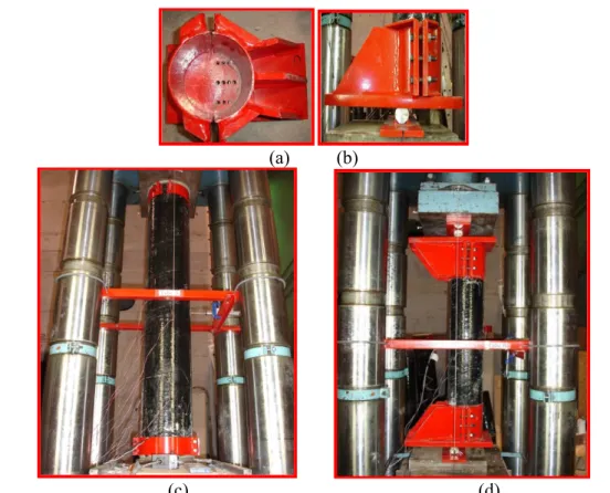
Figure 3-3-Test set up for concentric and eccentric axial load: (a) Front view for rigid-steel frame; (b) Plane for rigid-steel frame; (c) Specimen under concentric axial load; (d) Specimen
under eccentric axial load 51
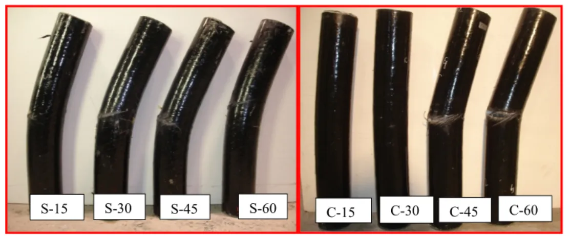
Figure 3-4– Failure modes of the concentrically loaded columns (S-00, C-00) 53 Figure 3-5– Failure modes of the eccentrically loaded column 54 Figure 3-6- Load-axial displacement curves for the steel and CFRP reinforced CFFT columns. 55 Figure 3-7- Load-lateral deformation relation for steel and CFRP reinforced CFFT columns 56 Figure 3-8- Load versus the eccentricity to diameter ratios 57 Figure 3-9-Load versus tensile bar strain (Steel & CFRP) 58
Figure 3-10-Load versus compression CFRP bar strain 59
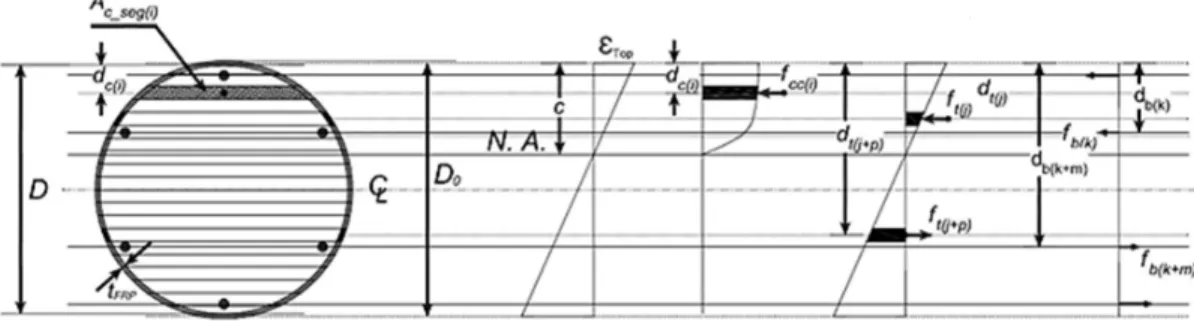
Figure 3-11- Load versus longitudinal and hoop tube strain 60 Figure 3-12-Normalized interaction diagrams for all columns 61 Figure 3-13- Stress-Strain curve for FRP-confined concrete 64 Figure 3-14- (a) Equivalent stress-strain distribution for CFFT columns; (b) Circular concrete
compression block trigonometric approach 67
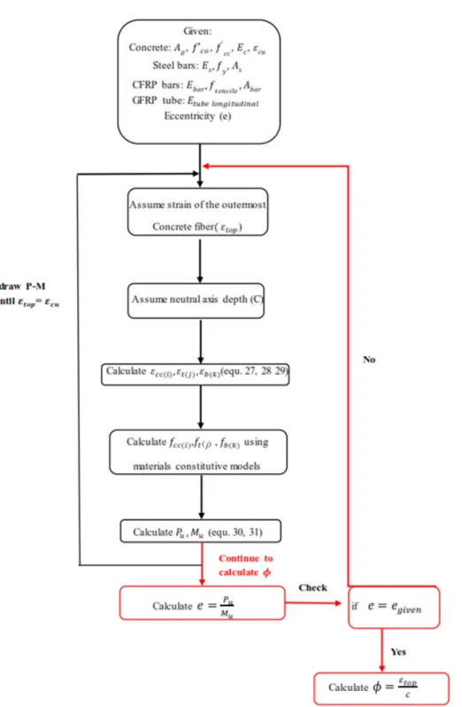
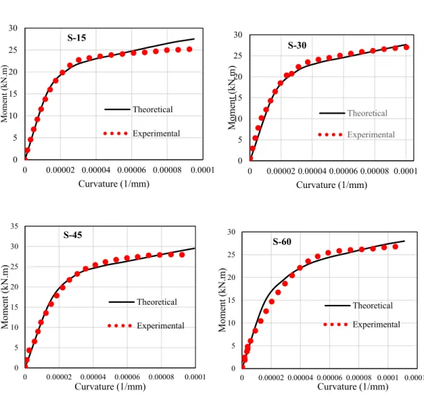
Figure 3-15- Discretized section for CFFT column and its strain and stress Profile 68 Figure 3-16- Flow chart illustrating steps for calculating axial load- moment -curvature 69 Figure 3-17- Comparison of experimental and theoretical axial and moment resistances 71 Figure 3-18- Experimental and theoretical moment-curvature diagrams for Steel CFFT
columns 73
Figure 3-19- Experimental and theoretical moment-curvature diagrams for CFRP CFFT
columns 74
Figure 3-20- Comparison for experimental moment curvature diagrams for S-60 &C-60 76
Figure 3-21-Effective flexure stiffness variations 77
Figure 3-22- Theoretical moment curvature diagrams considering design variables, (a) Steel
column; (b) Forces on the column; (c) Bending moment diagram (M= Pu (e+∆)) 87
Figure 4-2- Influence of eccentricity ratio and axial load ratio on EIe for Steel CFFT columns 94 Figure 4-3- Influence of eccentricity ratio and axial load ratio on EIe for CFRP CFFT columns 94 Figure 4-4- Schematic axial load-bending moment interaction diagram for cross section and
slender CFFT column 96
Figure 4-5- Stress and strain profiles of reinforced CFFT columns 99 Figure 4-6- Numerical integration for CFFT column deflection 100 Figure 4-7- Comparison between equation (4-8) and theoretical equation 102 Figure 4-8- Comparison of proposed design equations with simulated theoretical data; (a) Steel reinforced CFFT columns (Eq. (4-33)); (b) CFRP reinforced CFFT columns (Eq. (4-34)) 108 Figure 4-9- Flexure Stiffness of steel and CFRP reinforced CFFT columns as a function of eccentric ratio at: (a) service load; (b) ultimate load (Experimental results) 112 Figure 4-10- Comparison between ratio of experimental EIe and proposed EIe for steel and CFRP reinforced CFFT columns at: (a) service load; (b) ultimate load (Present Study) 113 Figure 4-11- Comparison between ratio of experimental EIe and proposed EIe for GFRP and CFRP reinforced CFFT columns at peak load (Previous Studies) 114 Figure 5-1– Stress-Strain curve for FRP confined concrete (Bazant and Cedolin, 1991) 124 Figure 5-2- Overview of fixed -fixed CFFT column under axial compressive load and stress
distribution before buckling and during buckling 127
Figure 5-3- Experimental values versus design equations (in terms of critical buckling stress) 128 Figure 5-4- Design curves for FRP reinforced CFFT columns 129 Figure 5-5- Effect of concrete compressive strength on critical slenderness ratio 132 Figure 5-6- Effect of FRP hoop stiffness on critical slenderness ratio 132 Figure 5-7 -Effect of FRP bar modular ratio on critical slenderness ratio 132 Figure 5-8- Effect of FRP bar reinforcement ratio on critical slenderness ratio 133 Figure 6-1-Kinematic vs. Strain energy for specimen 150IA 139 Figure 6-2-Stress-Strain Curve for FRP-Confined Concrete proposed by Lam and Teng 142 Figure 6-3-Experimental vs. Numerical Load-Displacement Curves for different columns listed
in Table 6-1 146
Figure 6-4-Comparison between the experimental failure mode and FE result for Hashin’s
damage parameter for short and slender columns 147
Figure 6-5-(a) Load history and (b) contact pressure along tube axis, for sample 60IA 148 Figure 6-6-(a) Load history and (b) contact pressure along tube axis, for sample 150IA 149 Figure 6-7-Results of the load deflection curve and elements of Specimen 60IA: (a) Load-Deflection curve, (b) Yielding of steel bars, (c) Local buckling of steel bars at failure, and (d) Rupture of FRP at failure indicated by Hashin’s damage parameter 151 Figure 6-8-Point of crushing of concrete at an element in the mid-section for specimen 60IA 151 Figure 6-9-Results of the load deflection curve and behavior of Specimen 90IA: (a) Load-Deflection curve, (b) Yielding of steel bars, (c) Local buckling of steel bars at failure, and (d) Rupture of FRP at failure indicated by Hashin’s damage parameter 152
Figure 6-10-Point of concrete crushing in specimen 90IA 153
Figure 6-11-Results of the load deflection curve and behavior of Specimen 120IA: (a) Load- deflection curve, (b) Start of the buckling mode, and (c) Failure and instability of CFFT 154
xvii Figure 6-13- Results of the load deflection curve and behavior of Specimen 150 IA: (a) Load- deflection curve, (b) Start of the buckling mode, and (c) Failure and instability of CFFT. 156 Figure 6-14- Load-displacement curves (a) specimens with (kl/r=8) with different FRP Layers, (b) specimens with (kl/r=20) with different FRP Layers, (c) specimens with (kl/r=8) with different fiber orientation, (d) specimens with (kl/r=20) with different fiber orie 160
List of Tables
Table 3-1– Test matrix and summery of test results 49
Table 4-1- Specimens details and summary of test results (Abdallah et al.,2018) 93 Table 4-2 - Different parameters of reinforced CFFT Columns ̽ 101 Table 4-3– Comparison of EIe for Steel and CFRP reinforced CFFT columns at service and
ultimate loads 111
Table 5-1— Test matrix, specimens details and test results (Mohamed and Masmoudi,2010) 120 Table 5-2— Properties of the tubes used in the parametric study 131 Table 6-1-Experimental Test Matrix and Results (Mohamed et al. 2010) 138
Table 6-2-Mechanical Properties of a GFRP Lamina 142
Table 6-3-Hashin’s Damage Parameters 143
CHAPTER 1
I
NTRODUCTION
1.1
General Background
Corrosion of steel reinforcement causes continual degradation to infrastructures worldwide, which has challenged engineers involved in designing and improving reinforced concrete structures. Fibre reinforced polymers composite materials have proven to be a solution for the corrosion problem due to its high corrosion resistance where FRP reinforcement have been introduced to concrete structures in the form of bars, tubes and grids in a wide variety of forms, types and characterizations. Recently, the use of fibre reinforced polymers (FRP) tubes, as structurally integrated stay in place forms for concrete members, such as beams and columns has emerged as an innovative solution to the corrosion problem and has saved millions of dollars spent yearly in reparation of concrete structures. The FRP tube is used mainly in structures subjected to harsh corrosive environment as an alternative to conventional reinforced concrete and steel components especially in tidal areas for marine piles and zones where de-icing is used. The FRP composite tube act as a stay in place formwork to contain fresh concrete which saves the cost of formwork used in precast and cast in-place industries and provide a light weight protective jacket. Different parameters including fibre orientation, fibre thickness, type of fibres and number of fibres layers in the FRP tube should be thoroughly investigated to ensure the optimum design for each individual application. This research investigated these different parameters through different parametric studies.
Generally, the use of FRP tubes as an external confinement for concrete structures is rapidly increasing. Nevertheless, its use as an external confinement in concrete columns reinforced with carbon FRP bars (CFRP) has not been thoroughly investigated. Most of the design provisions incorporated in codes and design guides are based on the design formulas of
members reinforced with conventional steel considering some modifications to account for the substantial differences between FRP and steel reinforcement.
Many researchers have investigated the behavior of concrete-filled fibre reinforced polymers (FRP) tube CFFT columns reinforced with conventional steel and FRP bars under concentric loads. On the other hand, the behavior of CFFT columns reinforced with FRP bars under eccentric load has not yet well investigated. This creates a research gaps in need of valuable investigations to introduce appropriate provisions in guidelines and codes for the design issues of FRP reinforced CFFTs columns under concentric and eccentric loads
1.2
Research Objectives
This research originally discussed the behavior of reinforced circular full-scale CFFT columns under concentric and eccentric compression. The main longitudinal reinforcement used was steel and CFRP bars. The efficiency of the CFRP bars as an alternative reinforcement was compared to steel, in addition to the efficiency of the GFRP tube as an external confinement. The interaction diagrams and moment-curvature curves were developed theoretically for all specimens and compared to the experimental results. The research also discussed the issue of compression contribution of CFRP bars and recommendations were presented. Moreover, the research proposed new design equations for the effective flexural stiffness of CFFT columns. Finally, using finite element modelling to provide insights of the structural behavior of the CFFT columns.
The main objectives of this research could be summarized as follow;
1. Investigating the behavior and failure mechanism of reinforced CFFT columns subjected to eccentric loading and comparing it to the behavior of their counterparts subjected to concentric loading.
2. Studying the effect of reinforcement type (Steel or CFRP bars) and eccentricity to diameter ratio (e/D) on the behavior of CFFT columns. 3. Developing complete interaction diagrams for steel and CFRP reinforced
1.3 Methodology 3
4. Studying the moment-curvature behavior of reinforced CFFT columns. 5. Developing new expressions for the effective flexural stiffness of CFFT
columns based on experimental and theoretical simulations.
6. Understanding the instability buckling behavior of FRP reinforced CFFT columns and developing a new slenderness limit equation for design purposes. 7. Providing insight to the behavior of CFFT columns using finite element
analysis.
A general objective could be assigned for this research as the possibility of using CFRP bars in CFFT columns under concentric and eccentric compression loadings and providing design provisions and recommendations for codes and guidelines.
1.3
Methodology
To achieve the above-described objectives, a research plan including experimental program and theoretical studies were conducted. The experimental program included testing of full-scale circular CFFT columns reinforced with carbon FRP as well as steel reinforcement. The results were discussed in terms of general behavior, effect of test parameters, interaction diagrams and moment-curvature behavior. On the other side, theoretical studies were prepared to analytically develop the interaction diagrams of the tested specimens along with parametrical investigation. The effective flexural stiffness for the CFFT columns was investigated. The slenderness limit for designing FRP reinforced CFFT columns to avoid column instability was studied. The following flow chart summarized the methodology prepared for this work.
1.4 Thesis organization 5
1.4
Thesis organization
The thesis first begins commonly with a short literature review in Chapter 2.
Chapter 3 (1st article) presents the results of an experimental investigation on the eccentric
behavior of circular (steel or CFRP) reinforced CFFT columns. The axial force–moment interaction diagrams were predicted based on the principles of strain compatibility and internal force equilibrium and layer by layer approaches. The moment-curvature behavior was presented and discussed for all specimens. Furthermore, a comprehensive parametric investigation was performed to generate numerous moment-curvature diagrams.
Chapter 4 (2nd article) presents new developed equations of Effective Flexural stiffness of
reinforced and unreinforced CFFT columns based on experimental parametric study and theoretical simulation. Developed equations were compared with experimental effective stiffness at service and ultimate loads.
Chapter 5 (3rd article) presents a theoretical study for the buckling instability analysis of FRP
reinforced CFFT columns. A new equation was suggested for the critical slenderness ratio of CFFT columns for safe design values. A parametric study was conducted to accounts for the effect of different parameters on the buckling behavior of FRP reinforced CFFT columns
Chapter 6 (4th article) presents a nonlinear finite element analysis using ABAQUS software
to understand failure mechanism of CFFT columns and provide deep explanation for experimental observations where test measurements are impossible. This model accounts for cracking and plasticity of concrete and include the effect of material and geometric nonlinearities. A parametric study was conducted to examine the effect of different key parameters on the ultimate capacity and failure mode of CFFTs, namely, number of FRP layers, fiber orientation and reinforcement ratio.
The last Chapter of the thesis, Chapter 7, presents some detailed conclusions of the results obtained from the experiments and analyses with respect to observations and highlights discussed throughout the thesis in addition to recommendations for future work.
CHAPTER 2
L
ITERATURE REVIEW
2.1
Background on Materials
2.1.1
FRP COMPOSITE MATERIALS
Fibre Reinforced Polymers have been extensively used over the past two decades in the construction industry, this refers to its several significant advantages which could be summarized as follows:
- Light weight which results in speed and ease of installation - High strength to weight ratios
- Outstanding durability in severe environments (Marine conditions, de-icing salts, Chemical products and Moisture)
- High energy absorption
- Its design adaptability as it can be fabricated in wide range of shapes and sizes including bars, tubes, sheets and plates.
Although FRP has been used for rehabilitation and strengthening of existing structures and buildings its use in new construction is becoming more prevalent. FRP composite materials have been used as internal and external reinforcement for concrete structures. FRP bars have been used as internal reinforcement for concrete slabs, barrier walls, bridge decks, and other reinforced pavements corrosive environments (Al-Sayed et al., 2000). In addition FRP composites have been used as an external confinement for strengthening and rehabilitation of structures in terms of sheets, wraps and tubes. One of the most promising confinement techniques that has been used extensively in the recent years is the FRP
composite tube. The FRP tube is used mainly in structures subjected to harsh corrosive environment as an alternative to conventional reinforced concrete and steel components especially in tidal areas for marine piles and zones where de-icing is used, in these areas the conventional materials as steel, timber and reinforced concrete become subjects to rotten, corrosion and disintegration. The FRP composite tube provide a light weight protective jacket and stay in place formwork to contain fresh concrete which saves the cost of formwork used in precast and cast in-place industries. Different parameters are provided by this system to achieve optimum design for each individual application including, fibre orientation, concrete wall thickness, type of fibres and number of fibres layers in the composite shells.
FRP tubes may be manufactured using different techniques including, manual layup, autoclave molding, filament winding, pultrusion and resin transfer molding, though filament winding and plutrusion are considered the most common techniques in forming hollow tubular sections. According to (Ozbakkaloglu & Vincent 2014) , FRP tubes manufactured automatically by using a filament winding technique provide greater strength and strain enhancement for CFFTs compared with tubes manufactured manually using a wet layup process.
2.2
Behavior of CFFTs
2.2.1
Axial Behavior of CFFT
Saafi et al. (1999)
Saafi et al. (1999) conducted experimental and analytical studies of the performance of concrete columns confined with carbon and glass FRP composite tubes. Concrete filled FRP tubes are instrumented and tested under uniaxial compressive load. Test variables include type of fibre, thickness of tube, and concrete compressive strength.
To test the performance of concrete confined with FRP tubes, 30 concrete cylinders (18 concrete-filled FRP tubes and 12 plain concrete) were tested under compression. All specimens consisted of short columns with a length-to-diameter ratio of 2.85. Each
2.2 Behavior of CFFTs 9
specimen measured 152.4 mm in diameter and 435 mm in length. The FRP tubes used in this study were made of glass-fibre and carbon-fibre filament winding-reinforced polymers—all consisting of 60 percent fibre and 40 percent polyester resin. The fibres oriented in the circumferential direction of the cylinders. Three tube thicknesses of each fibre type were used. The thicknesses of the glass tubes were 0.8, 1.6, and 2.4 mm, and the carbon tubes were 0.11, 0.23, and 0.55 mm.
It was concluded that:
1. The FRP tube composites are an effective means of confinement. They significantly increase both the strength and ductility of concrete. The rate of increase is dependent upon the tube thickness and the mechanical properties of the composite tube and the unconfined concrete.
2. The stress-strain response of FRP tube-confined concrete is bilinear in both the axial and lateral direction. The first slope of the response depends on the concrete core, while the stiffness of the FRP tube controls the second slope. The bent point between the two slopes takes place at stress levels slightly higher than the unconfined strength of the concrete core. 3. The proposed equations to estimate the ultimate stresses and failure strains produce satisfactory predictions as compared to current design equations available in the literature. The effect the lateral strain is considered in the proposed equations.
4. The predicted stress-strain response in both axial and lateral directions of concrete-filled FRP tubes compares satisfactorily with the experimental values. However, the model underestimates the results of concrete columns confined with FRP composite sheets.
Mohamed and Masmoudi (2010)
Mohamed and Masmoudi (2010) investigated the behaviors of small and medium internally reinforced CFFT columns with different slenderness ratios under concentric axial loading and two types of concrete were presented. The experimental results for 20 unconfined cylinders,
eight CFFT cylinders, eight CFFT columns and one control specimen were investigated. The slenderness ratios ranged between 2, 4, 6 and 8 were examined in the present study. The findings of this research can be summarized as follows:
1. The longitudinal steel bars provide significant dowel action, which delays the dilation of concrete core inside CFFT, thereby improving the ductility of CFFT columns. 2. The ultimate strength of the CFFT is mainly dependent on the stiffness of the GFRP
tubes, and it is more effective for normal than medium strength concrete. 3. The failure modes for CFFT are affected by the slenderness ratio.
4. Increasing the slenderness ratio (H/D) of the reinforced CFFT specimens more than six reduce significantly the ultimate load capacity due to the buckling phenomenon. 5. The average ultimate rupture strain of the GFRP tubes is close to the rupture strain
obtained from split-disk test. Ozbakkaloglu and Vincent (2014)
Ozbakkaloglu and Vincent (2014) conducted an experimental study on the axial compressive behavior of 83 monotonically-loaded circular CFFTs. The effects of fiber type, concrete strength, specimen size, and manufacturing method on the compressive behavior of CFFTs were investigated. The CFFTs were manufactured with carbon FRP (CFRP), high-modulus CFRP (HMCFRP), or aramid FRP (AFRP) tubes, and their average unconfined concrete strengths ranged between 34–110 MPa. The diameters of the test specimens ranged from 75– 300 mm with all specimens maintaining a 2∶1 height-to-diameter ratio. The effect of the CFFT manufacturing method was investigated through AFRP specimens that were manufactured through either an automated filament winding or manual wet layup technique. The following points were concluded:
1. The specimen size does not have a significant effect on the compressive behavior of CFFTs and a strong correlation exists between the ultimate tensile strain (εfu) of the
fibers and the ultimate axial strain (εcu) of the CFFTs.
2. Adequately confined high-strength CFFTs can exhibit highly ductile behavior. However, the behavior of these CFFTs is highly sensitive to the level of confinement,
2.2 Behavior of CFFTs 11
and lightly confined HSCFFTs may not be able to maintain their load-carrying capacity after their initial peak strengths are attained.
3. For a given nominal confinement ratio (
f
lu/
f
'
co) an increase in concrete compressivestrength (
f '
co) and associated brittleness leads to an overall decrease in the strengthenhancement ratio (
f
'
cc/
f
'
co), the strain enhancement ratio (
cu/
co) and the strainreduction factor (Kɛ ).
4. FRP tubes manufactured automatically by using a filament winding technique provide greater strength and strain enhancement (
f
'
cc/
f
'
co and
cu/
co) for CFFTs comparedwith tubes manufactured manually using a wet layup process.
2.2.2
Flexure Behavior of CFFT
Generally the circular CFFT columns experience better performance than the conventional RC columns in terms of flexure strength and ductility, CFFT columns can exhibit superior additional flexural capacities in the post-yielding stage. This was attributed mainly to the FRP tube contributed in the flexural reinforcement and it forced the concrete core to withstand higher strains.
Fam and Rizkalla (2002)
Fam and Rizkalla (2002) proposed an analytical model proposed to predict the behavior of concrete-filled rectangular fiber reinforced polymer tubes (CFRFT) subjected to bending, axial compression loading or combined loading. The model accounts for different laminate structures of the flange and the web of the FRP tube through the Classical Lamination Theory (CLT). The gradual reduction of stiffness resulting from the progressive failure of different FRP layers oriented at various angles is accounted for through the Ultimate Laminate Failure (ULF) approach. The model adopts the
cracked section analysis using layer-by-layer approach and accounts for both totally filled tubes and tubes with inner voids.
The following conclusions were drawn:
1. Conventional RC sections of the same moment capacity as CFRFT have higher axial compressive strength, while RC sections with the same axial strength as CFRFT have substantially lower flexural strength.
2. RC sections with similar flexural strength, reinforcement ratio, or reinforcement index to CFRFT are significantly stiffer, but have very low ductility. RC sections with reinforcement ratio based on equivalent axial stiffness (EA) of reinforcement, are quite ductile but substantially lower in flexural capacity than CFRFT.
3. A small fraction of carbon fibers placed longitudinally in the FRP flange of the tube (hybrid laminate), could result in significant gain in flexural strength and stiffness.
4. In CFRFT flexural members, the void size can be optimized for maximum strength-to self-weight ratio.
5. Increasing the wall thickness for a given laminate or increasing the percentage of fibers in the axial direction of the laminate results in increasing the flexural strength and stiffness of CFRFTs. However, failure mode could change from tension to compression. Concrete strength, on the other hand has marginal effect on the flexural response of the CFRFTs.
6. The balanced reinforcement ratio of CFRFT under pure bending depends on the laminate structure. It reduces gradually with increasing axial stiffness of the laminate of the tube.
7. Variation of flexural strength with reinforcement ratio in CFRFT is quite different from singly reinforced RC sections but very similar to that of doubly reinforced RC section.
2.2 Behavior of CFFTs 13
8. There is insignificant confinement effect on enhancing the strength of CFRFT. Unlike circular members, the unconfined concrete stress-strain curve used in the model predicts well the behavior of CFRFTs under combined bending and axial loading.
9. Increasing the wall thickness or percentage of fibers in axial direction of the tube, results in large gain in flexural strength. In thin tubes, increasing the percentage of fibers in axial direction has insignificant effect on axial strength.
FAM et al. (2003)
Fam et al. (2003) conducted an experimental program and proposed an analytical model for 10 concrete filled GFRP circular tubes under concentric and eccentric axial loads using column specimens as well as under pure bending using beam specimens for the given specimens. Two different laminate structures were used for the GFRP tubes, Axial load/bending moment interaction curves are presented. It has been concluded that:
1. Interaction curves of concrete-filled FRP tubes of moderate diameter-to-thickness ratios are similar to that of reinforced concrete members. As axial load increases, the moment capacity also increases and failure is governed by rupture of the FRP tube at the tension face. A balanced point is reached, beyond which the moment capacity is reduced by increasing the axial load and failure is governed by crushing of the FRP tube in the compression side; 2. The variable confinement model of concrete provides the best prediction of
interaction curves. The full confinement model also provides reasonable prediction, however, for tubes with adequate confinement stiffness (as Type I); it overestimates bending capacity at low axial loads;
3. The unconfined concrete model significantly underestimates the interaction diagrams for concrete-filled FRP tubes with adequate confinement stiffness.
The unconfined model with extended strain softening, however, predicts the pure bending strength very well;
4. For a given laminate structure, increasing the wall thickness of the tube increases the axial and bending strengths as evident from the increased size of interaction diagram. The curve could, however, change from the typical shape with the balanced point being the maximum moment (for small thickness tubes) to a shape with the pure bending strength being the maximum moment, and the full curve is governed by compression failure (for large-thickness tubes, particularly for tubes with higher axial stiffness); 5. For both concrete-filled thin and thick tubes, increasing the ratio of fibers in
the axial direction significantly increases the flexural strength;
6. Increasing the ratio of fibers in the hoop direction would increase the axial strength of concrete-filled thin tubes only;
7. The axial strength of concrete-filled thick tubes tends to increase by increasing the amount of fibers in the axial direction rather than in the hoop direction. In thick tubes, the contribution from axial stiffness of the tube is more significant than the gain from confinement of concrete;
8. For small-thickness tubes, changing the proportion of fibers in the axial and hoop directions results in a family of interaction curves, intersecting at certain points, which provide an optimum laminate structure for a particular eccentricity for a given wall thickness. For relatively thick tubes, the interaction curves do not intersect and the optimum laminate seems to be the one with maximum axial stiffness and minimum hoop stiffness, regardless of the eccentricity; and
Fam and Rizkallah (2005)
Fam and Rizkalla (2005) conducted an experimental study on three beams and five short columns, consisting of glass fiber reinforced polymer concrete-filled rectangular filament-wound tubes (CFRFTs). The tubes included fibers oriented at ±45° and 90° with respect to the
2.2 Behavior of CFFTs 15
longitudinal axis. Additional longitudinal fibers [0°] were provided in flanges for flexural rigidity. Beams included totally filled tubes and a tube partially filled with concrete, which had a central hole for reducing deadweight. The effect of reinforcement ratio was examined by using tubes of two different sizes. Flexural behavior of CFRFT was compared to concrete-filled rectangular steel tubes (CFRSTs) of similar reinforcement ratios. Short columns were tested under eccentricity ratios (e/h) of 0, 0.09, 0.18, and 0.24, where h is the section depth. Transverse strains were measured around the perimeter of concentrically loaded column to evaluate confinement effect. It was concluded that:
1. CFRFT provide feasible and easy ways to construct structural members for beam and column applications. The FRP tube provides permanent formwork and is the sole reinforcement or concrete in the axial and transverse directions. Unlike steel tubes, strength and stiffness of FRP tubes can be controlled independently in the flanges and webs and also in both directions.
2. The laminate stress–strain behavior of FRP tubes could be quite nonlinear. Laminates with fibers oriented at ±45° show significant nonlinearity under tension and compression. Nonlinearity could also result from progressive failure of layers oriented at various directions.
3. The load–deflection behavior of CFRFT beams is slightly nonlinear due to the nonlinearity of both FRP tube and concrete. The beam with inner hole had an overall strength-to weight ratio, 77% higher than the totally filled beam. Further study is needed to optimize the size and shape of the concrete flange in partially filled beams to avoid premature compression failure.
4. Totally filled CFRFT beam failed by rupture of FRP in the tension side while the beam with a hole failed by inward buckling and fracture of the concrete compressive flange. In both beams outward buckling of the FRP compressive flange was observed.
5. CFRFT beams with [90/ ±452 /02 /90] s GFRP flanges, which have
Similar beams, but with b/t=30, fail by local buckling at an axial strain of only 25% of the ultimate compressive strain of the flange.
6. The compression zone depth in CFRFT beams is stable after cracking at 20– 30% of the section depth, throughout the loading history. Linear strain distribution is also observed.
7. The flexural strength of CFRFT is comparable to that of CFRSTs of similar reinforcement ratio. Their load–deflection behavior, however, is quite different. The CFRSTs are initially stiffer due to the higher Young’s modulus of steel, compared to GFRP. Once the steel yields, plastic behavior is observed, whereas CFRFTs do not show plasticity.
8. Short CFRFT columns loaded over the entire cross section could fail in a brittle manner by fracture of the FRP tube at the round corner, due to a high level of biaxial stresses.
9. The round corners of CFRFT columns provide limited confinement. The flat sides of the FRP tube bends outwards and causes the column to bulge and the concrete core to lose restraint. Consequently, the confinement effect is further reduced.
Hadi et al. (2016b)
Hadi et al. (2016b) investigated the axial and flexural behavior of concrete filled Glass FRP (GFRP) tube columns with and without GFRP bar. The experimental program included four steel RC specimens (REF), four GFRP-CFFT specimens (GT), and four GFRP bar–reinforced GFRP-CFFT (GTGR) specimens with an outer diameter of 205–206 mm and a height of 800– 812 mm. The specimens were tested under concentric and 25- and 50-mm eccentric axial loads and four-point load. The experimental results showed that GFRP bar–reinforced GFRP-CFFT specimens sustained higher peak axial loads, axial and lateral deformations at peak axial load, and flexural loads than GFRP-CFFT specimens without reinforcing GFRP bars and steel RC specimens. Axial load and bending moment (P-M) interactions of GFRP-CFFT specimens with and without reinforcing GFRP bars and steel RC specimens were analytically modeled. The following conclusions were drawn;
2.3 Field Applications of CFFT 17
1. The experimental P-M interaction of the GTGR group was larger than the P-M interactions of the GT and REF group as the GTGR group resisted higher axial and flexural loads and lateral deformations at peak axial loads than the GT and REF groups. The confinement effectiveness of GFRP tube was reduced with the increase in the applied load eccentricity.
2. For the GT and GTGR groups, the analytical axial loads and bending moments calculated by using Samaan et al.’s (1998) and Lam and Teng’s (2003) stress-strain models underestimated the experimental axial loads and bending moments, resulting in conservative estimates. Also, the layer-by-layer numerical integration method adopted in this study can be used to accurately compute the axial loads and bending moments of the GT, GTGR and REF groups.
2.3
Field Applications of CFFT
Concrete Filled FRP Tube (CFFT) are used in many field applications as piles, finder piles, piers and bridge deck and girders.
Fam et al. (2003a)
Fam et al. (2003a) presented a detailed review of applications of CFFT in marine piles where they discussed the different types of marine piles as follows:
(a) Fender Piling: In front of marine structures, piles are used extensively as vertical fenders, as shown in Figure 2-1.a. The fender piles act as a buffer to absorb and dissipate the impact energy of the ship during berthing and prevent vessels from going underneath the pier.
(b) Dauphins: Dauphins are groups of piles, as shown in Figure 2-1.b placed near piers and wharves to guide vessels into their moorings, to keep them away from structures or to serve as mooring points.
(c) Light Structural piling: The piles can be used to support the loads of light-duty piers and wharves. In this application, bracing between piles is normally used to increase the strength and stiffness of the foundation of the structure as shown in Figure 2-1.c.
(d) Bridge Pier Protection: Piles and dauphins can also be used to create protective structures for bridge piers and to guide vessels into the channel and away from bridge supports as shown in Figure 2-1.d.
They conducted an experimental program over a period of six years to evaluate the structural performance of the CFFT composite piles. During this period, test results and recommendations were continuously fed to the industry, including the design engineers and contractors in charge of the field projects stated above. Full scale tests have been conducted on the most commonly used size of the composite pile (the 323 mm diameter pile), including axial compression short column tests, bending tests using beam specimens and combined bending and axial compression tests using eccentrically loaded columns tested at various eccentricities to establish the axial load - bending moment interaction curves of the pile, and they discussed the following points:
1. Concrete-filled FRP tubes (CFFT) have indeed gained large potential for marine pile applications. The system is becoming more popular as it provides several advantages over conventional piles. Non-corrosive characteristics, elimination of internal steel reinforcement and utilizing the FRP tube as reinforcement and permanent formwork are the most unique features.
2. Eight different field projects have been successfully completed using the CFFT composite piles along the east and west coasts of the United States. The piles were utilized in a verity of configurations including fendering, dauphins, support of light structures and bridge pier protection.
3. The composite piles in the field projects have been in service for several years and some went through severe hurricanes. To date, based on regular inspections, the piles are performing very well.
2.4 Behavior of RC Columns Reinforced with FRP Bars 19
Figure 2-1-Different applications of CFFT composite marine piles (Fam et al., 2003a)
2.4
Behavior of RC Columns Reinforced with FRP Bars
2.4.1
Columns Behavior under Concentric Loading
Lotfy ehab. (2010)Lotfy (2010) conducted an experimental investigation of the axial behavior of small scale square reinforced concrete columns with fibre reinforced polymer (FRP) bars, a series of 8 columns were tested in a vertical position and under compressive axial static loading. All columns had the same dimensions 250*250mm and 1250mm height, main reinforcement 4#12mm, 6#12mm, and 8#12mm, the transverse reinforcement was ø6@120mm closed stirrups along column. The major parameters included in this research were the main reinforcement ratios, the main reinforcement types, the transverse reinforcement ratios in the column, and the characteristic strength of concrete.
It was concluded that:
1. Tested column with steel reinforcement has ductility more than column with GFRP reinforcement, where ultimate load, ultimate strain and initial cracking loads of column
with steel reinforcement increase with 118, 117 and 117% respectively of column with GFRP reinforcement.
2. Increasing of main reinforcement ratios with GFRP bars increase the ductility of cross section, so it has a significant effect on the initial cracking loads, ultimate strain, and ultimate loads that the columns resist.
3. Increasing of GFRP reinforcement ratios from 0.723 to 1.08% has a noticeable significant effect on the all behavior of tested columns more than the increase of reinforcement ratios from 1.08 to 1.45%.
4. Increasing of transverse reinforcement ratio leads to increase the toughness and ductility of tested columns with GFRP bars, where the increase of transverse reinforcement ratios confines the columns so it is lead to increasing the ultimate loads which the columns resisted, hence increasing ultimate strain, and initial cracking loads. And the column with GFRP bars has toughness and ductility more than column with steel bars and normal transverse reinforcement distribution.
5. Increasing of characteristic strength of concrete has significant effect on the behavior of tested columns where increase toughness and ductility of tested columns.
De luca et al. (2011)
Luca et al. (2011) conducted an experimental program on full-scale GFRP reinforced concrete (RC) columns under pure axial load using specimens with a 24 x 24 in. (0.61 x 0.61 m) square cross section. The study was conducted to investigate whether the compressive behavior of longitudinal GFRP bars impacts the column performance, and to understand the contribution of GFRP ties to the confinement of the concrete core, and to prevent instability of the longitudinal reinforcement. The following conclusions were drawn:
1. The behavior of RC columns internally reinforced with GFRP bars is very similar to that of conventional steel
2.4 Behavior of RC Columns Reinforced with FRP Bars 21
RC columns if the longitudinal reinforcement ratio is equal to 1.0%. No appreciable difference was observed in terms of peak capacity. Failure of the steel RC specimen happened due to buckling of the longitudinal reinforcement when still in the elastic range, whereas the GFRP RC specimens failed due to the crushing of the concrete core at axial strains higher than those measured in the steel RC counterpart.
2. The use of longitudinal GFRP bars is not detrimental to the performance of RC columns. The contribution of the GFRP bars to the column capacity, however, was less than 5% of the peak load, which is significantly lower than that of approximately 12% of the steel bars in the steel RC counterpart. It is concluded that the contribution of the GFRP bars may be ignored when evaluating the nominal capacity of an axially loaded RC column.
3. The difference in the GFRP bar manufacturers does not affect the performance when bars are of comparable quality.
Tobbi et al. (2012)
Tobbi et al. (2012) conducted an experimental study on eight RC square columns 50 x 350 x 1400 mm (13.78 x 13.78 x 55.1 in.) to study their behavior under axial loads and to estimate the effect of FRP bars as longitudinal and lateral reinforcement on the strength and strain capacities of the concrete column. The eight columns were classified as follows, one made of plain concrete with no reinforcement, two steel RC columns reinforced by 8M15 bars, three GFRP columns reinforced by 8 #19 bars and two GFRP columns reinforced by 12 #16. All of the RC columns had similar areas of longitudinal reinforcement, comprising 1.9% of the gross section area Ag. The effect of different parameters were studied such as concrete cover, tie configuration and tie spacing. Figure 2-2 (a) and (b) show testing details and GFRP bar failure modes respectively.
1. The early spalling of the concrete cover resulted in a loss of axial capacity before any lateral confinement came into effect. After the concrete cover had completely spalled off, important gains in strength, ductility, and toughness were recorded for the concrete cores of well-confined specimens.
2. Studying tie configuration and spacing clarified the effectiveness of GFRP as transverse reinforcement in increasing strength, toughness, and ductility of the confined concrete core. Further research is needed to study limitations of tie spacing.
3. The strength reduction factor of 0.85 (the case for steel) can be adopted for GFRP-reinforced columns.
4. Setting the FRP compressive strength at 35% of the FRP maximum tensile strength yielded a reasonable estimate of ultimate capacity compared to the experimental results. More experimental evidence is needed, however, to more accurately define FRP compressive strength.
5. The GFRP bars used contributed 10% of column capacity, which is close enough to steel’s contribution (12%).
This proves that GFRP bars could be used in compression members provided there was adequate confinement to eliminate bar buckling.
2.4 Behavior of RC Columns Reinforced with FRP Bars 23
Figure 2-2-GFRP bar Failure (Tobbi et al., 2012)
The same authors conducted another experimental program (Tobbi et al. 2014) to study concrete columns reinforced longitudinally with glass FRP (GFRP), carbon FRP (CFRP), and steel bars and GFRP and CFRP transverse reinforcement subjected to concentric loading. Twenty concrete columns were tested measuring 350 x 350 x 1400 mm (13.8 x 13.8 x 55.1 in.) subjected to concentric compressive loading. One column was kept un-reinforced (plain concrete) while the remaining 19 were internally reinforced with FRP and steel according to different parameters.
All used transverse reinforcements were GFRP or CFRP, while the longitudinal reinforcement was GFRP, CFRP, or steel bars.
Different parameters were studied including the shape of transverse reinforcement, longitudinal reinforcement ratio, longitudinal reinforcement material (GFRP, CFRP, or steel), FRP-transverse reinforcement material (GFRP or CFRP), the diameter of the transverse reinforcement (No. 9.5 and 12.7 mm [No. 3 and No. 4]), transverse reinforcement spacing, and confining volumetric stiffness. Figure 2-3 shows Failure mode of columns reinforced longitudinally and transversely with FRP. Finally the following points were concluded:
1. The confinement efficiency of closed FRP transverse reinforcements cut from continuous square spiral is higher than C-shaped type transverse reinforcements. 2. The ultimate axial strain of columns reinforced longitudinally with FRP is almost 30%
3. The ultimate axial compressive strain for columns reinforced longitudinally and transversally with FRP can reach a value on the same order of magnitude as the FRP ultimate tensile strain of the longitudinal bars under good confinement conditions. 4. The contribution of FRP longitudinal reinforcement in concrete columns subjected to
axial concentric loading should not be neglected. A proposed equation based on elastic theory yields good predictions compared with laboratory test data.
5. FRP transverse reinforcement configuration and spacing are the most important parameters (compared with confinement provided by concrete cover) affecting confining efficiency in internally reinforced concrete columns under axial loading. 6. In the case of large spacing with low volumetric ratio, CFRP transverse reinforcement
performed significantly better than GFRP. Increasing the volumetric ratio while reducing spacing will eliminate the effect of material stiffness. In such cases, the GFRP transverse reinforcements are more cost effective.
7. Columns internally reinforced with a combination of steel longitudinal bars and FRP transverse reinforcements exhibit good gains in terms of compressive strength and ultimate axial strain. Nonetheless, the use of FRP transverse reinforcement should still improve corrosion resistance of a column by adding an extra 10 mm (0.4 in.) of cover to the steel.
8. The presented study showed the applicability of exclusively reinforcing the columns with FRP and subjected to on centric load. Further research elaboration is necessary to investigate the behavior of FRP reinforced columns loaded laterally or subjected to load combination (axially and laterally).