m S H E R B R O O K E
Faculte de genie
Departement de genie civil
TIME-DEPENDENT BEHAVIOUR OF FIBRE REINFORCED
POLYMER (FRP) BARS AND FRP REINFORCED CONCRETE
BEAMS UNDER SUSTAINED LOAD
LE COMPORTEMENT A LONG TERME DES BARRES EN
POLYMERES RENFORCES DE FIBRES (PRF) ET DES
POUTRES EN BETON ARMEES AVEC DES BARRES EN PRF
SOUS CHARGE PERMANENTE
A Thesis Submitted in Partial Fulfilment of the Requirements for the Degree of
Doctor of Philosophy
Speciality: Civil Engineering
Tarik A. YOUSSEF
1
*
1
Published Heritage Direction du
Branch Patrimoine de l'6dition 395 Wellington Street Ottawa ON K1A 0N4 Canada 395, rue Wellington Ottawa ON K1A 0N4 Canada
Your file Votre reference
ISBN: 978-0-494-70621-3
Our file Notm reference
ISBN: 978-0-494-70621-3
NOTICE:
The author has granted a
non-exclusive license allowing Library and Archives Canada to reproduce, publish, archive, preserve, conserve, communicate to the public by
telecommunication or on the Internet, loan, distribute and sell theses
worldwide, for commercial or non-commercial purposes, in microform, paper, electronic and/or any other formats.
AVIS:
L'auteur a accorde une licence non exclusive permettant a la Bibliotheque et Archives Canada de reproduire, publier, archiver, sauvegarder, conserver, transmettre au public par telecommunication ou par I'lnternet, preter, distribuer et vendre des theses partout dans le monde, a des fins commerciales ou autres, sur support microforme, papier, electronique et/ou autres formats.
The author retains copyright ownership and moral rights in this thesis. Neither the thesis nor substantial extracts from it may be printed or otherwise reproduced without the author's permission.
L'auteur conserve la propriete du droit d'auteur et des droits moraux qui protege cette these. Ni la these ni des extraits substantiels de celle-ci ne doivent etre imprimis ou autrement reproduits sans son autorisation.
In compliance with the Canadian Privacy Act some supporting forms may have been removed from this thesis.
While these forms may be included in the document page count, their removal does not represent any loss of content from the thesis.
Conformement a la loi canadienne sur la protection de la vie privee, quelques formulaires secondaires ont ete enleves de cette these.
Bien que ces formulaires aient inclus dans la pagination, il n'y aura aucun contenu manquant.
ABSTRACT
Greater attention has been given recently to the long-term performance of FRP-reinforced concrete elements (beams in particular). Despite the conducted effort in the past two decades, the area of long-term behaviour of FRP reinforced concrete is virtually considered virgin grounds. Decision makers and designers, alike, are in dire need for such hard-to-obtain information content. Such necessity renders this type of research a core requirement to promote the widespread of FRP-internal-reinforcement usage.
In this respect, an extensive experimental/research program has taken place at the University of Sherbrooke FRP Durability Facility. The program, consisting of four phases, studies the creep performance of FRP bars as well as the overall long-term behaviour of FRP reinforced concrete beams. Phase 1 deals with the creep performance of two types of GFRP bars subjected to different levels of sustained axial load; causing creep rupture at higher levels. In Phase 2, six different types of GFRP bars are tested under two levels of allowable service load, according to the currently available North American standards. The test duration, for the two phases, exceeded 10000 hours (417 days) wherein regular monitoring of creep strain evolution took place and the creep coefficient of GFRP bars was calculated. Residual tensile tests and microstructural analysis followed the long-term testing period. It was found that 45 % of the GFRP bars' tensile strength, fUiave, is a safe limit for GFRP exhibiting sustained load, in standard laboratory conditions. Microstructural analysis shows that the increase in creep strain, after the 10000 hour period, is negligible for GFRP bars under allowable service load.
Phase 3 consists of twenty reinforced concrete beams (ten pairs) comprising GFRP, CFRP, and steel reinforcing bars. The dimensions of which are 100 mm x 150 mm x 1800 mm, installed under third-point sustained load, for a period exceeding one year. Exhibiting a maximum applied moment of 25 % of their nominal moment capacity, Mn, all beams were
regularly monitored in terms of (i) time-dependent deflection, (ii) strain increase in concrete and reinforcement and (iii) crack widths. Theoretical predictions for immediate deflection were calculated, using three methods (ACI 440.1R-06, CAN/CSA S806-02 and the ISIS Canda Design Manual (2007)), and compared to the obtained experimental results. Results
showed that the calculations, regarding immediate deflection, under estimate by 67 %; underestimate by 10 %; overestimate by 11 %, for the aforementioned methods, respectively. The long-term to immediate deflection ratio, X, was calculated for all beams and compared to ACI 440.1R-06 and CAN/CSA S806-02 predictions. Results showed that the North American standards are conservative as regards long-term deflection prediction. Immediate crack width results were compared to the prediction equations adopted by ACI 440.1R-06 and CAN/CSA S6-06, on the one hand, and by the ISIS Canada Design Manual (2007) on the other hand. Satisfactory results were found when the kb bond-coefficient factor is taken as 1.2 and 1.0, respectively. From the obtained data, the time-dependent kt multiplier, accounting for crack
width increase after one year, was deduced as 1.7 and 1.5 for both models, respectively.
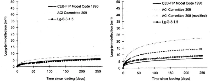
Phase 4 deals with four full-scale GFRP reinforced concrete beams, of dimensions (215 mm x 400 mm x 4282 mm), subjected to uniform distributed load for a period of six months. Sizeable concrete blocks (of dimensions 610 mm x 762 mm x 1219 mm and weight = 13334 kN) were arranged on top of the beams to simulate sustained uniform distributed load. The main study parameters, of this phase, are (i) bottom reinforcement ratio and (ii) type of upper/compression reinforcement (GFRP and/or steel). The applied moment ranges from 15 to 21 % of the nominal moment capacity for the beams. Numerical modelling took place using a computer program (Fortran-2003) based on the age-adjusted effective modulus method, to predict the long-term deflection of the beams. The creep and shrinkage coefficients were calculated based on the ACI Committee 209 recommendations (1992) and CEB-FIP Model Code (1990). The theoretical curves were in very good agreement with the measured values. Furthermore, the empirical models available in ACI 440.1R-06 and CAN/CSA S806-02 were used for long-term deflection prediction. These predictions showed that both models can serve as upper bound and lower bound limits for the measured long-term deflection curves, respectively. As regards crack width prediction, the equations adopted by ACI 440.1R-06 (same as that of CAN/CSA S6-06) and by the ISIS Canada Design Manual (2007) yield satisfactory results when the kb bond-coefficient factor is 1.2 and 1.0 respectively (similar to phase 3). For both equations the time-dependent kt multiplier is deduced as 1.4, after six
All four phases function in synergy to better understand the long-term behaviour of FRP reinforced concrete elements under different types of sustained load. This study presents the long-term performance data of 99 bar samples, 20 FRP and steel reinforced concrete beams under third-point load and four full-scale GFRP reinforced beams under uniform distributed load. Creep coefficients for different types of GFRP bars were calculated; microstructural analysis was conducted. The obtained data was used to verify existing empirical models in North American standards; numerical (finite difference) modelling was conducted and showed good agreement with the experimental results. The information content made available in this study, regarding the long-term behaviour of FRP reinforced beams is unprecedented.
RESUME
Une attention accrue a ete accordee recemment a la performance a long terme des elements en beton renforces de PRF. Malgre l'effort realise au cours des deux dernieres decennies, le domaine du comportement a long terme de beton arme de PRF est pratiquement considere comme un motif vierge. Les decideurs et les concepteurs, aussi bien, ont besoin de cette tres importante information. Cela rend la necessite de ce type de recherche une exigence fondamentale pour promouvoir la generalisation de l'utilisation de PRF comme renforcement interne.
A cet egard, un vaste programme experimental a eu lieu au laboratoire de durability de PRF de
l'Universite de Sherbrooke. Le programme, compose de quatre phases, a ete mis pour etudier le comportement au fluage de barres de PRF, ainsi que le comportement global a long terme des poutres en beton arme de barres de PRF. La phase 1 porte sur la performance au fluage de deux types de barres en PRFV soumis a differents niveaux de charge axiale constante; qui, pour des niveaux eleves, a cause la rupture de la barre en fluage. Dans la phase 2, six types differents de barres en PRFV sont testes dans deux niveaux de charge (15 % et 30 % de fu,ave)
de service (conformement aux codes disponibles en Amerique du Nord). Un suivi regulier de revolution de la deformation de fluage a eu lieu et le coefficient de fluage de barres en PRFV a ete calcule pour toute la duree des deux phases de l'essai (plus de 10000 heures ~ 417 jours). Des essais residuels de traction et une analyse microstructurale a suivi la periode d'essai a long terme. II a ete constate que a des fms de conception, 45 % de la resistance des barres en PRFV a la traction, fu,ave, est une valeur securitaire, dans des conditions standard de laboratoire. Les analyses microstructurales montrent qu'apres la periode de 10000 heures sous charge de fluage egale ou inferieure a 45 % de /Mave , il n'existe aucune degradation dans les
barres testees.
La phase 3 se comporte vingt poutres en beton (dix paires) renforcees de barres de PRFV (14 poutres), PRFC (4 poutres), et d'acier (2 poutres). Les dimensions des poutres sont de 100 mm x 150 mm x 1800 mm, installes sous une charge soutenue en flexion quatre points (trois tiers), pour une periode d'un an. La charge constante appliquee correspond a 25 % du moment
nominal, Mn, tous les poutres ont ete regulierement suiviez en termes (i) devolution des
deformations dans le beton et le PRF, (ii) fleche en fonction du temps, et (iii) la largeur des fissures. Les predictions theoriques pour la fleche immediate ont ete calculees, en utilisant trois methodes (ACI 440.1R-06, CAN/CSA S806-02 and the ISIS Canda Design Manual (2007)), et comparees aux resultats experimentaux. Les resultats ont montre que les calculs, de fleche immediate, sous-estimation de 67 %; sous-estiment de 10 %; surestimation de 11 %, pour les methodes ci-dessus, respectivement. La fleche a long-terme par rapport la fleche immediate, X, a ete calculee pour toutes les poutres et comparee aux predictions du ACI 440.1R-06 et CAN/CSA S806-02. Les resultats ont montre que les codes Nord Americains surestiment la prediction de fleche a long terme pour les poutres testees. Les resultats de largeur de fissures ont ete compares aux equations de prediction adopte par ACI 440.1R-06 et CAN/CSA S6-06, d'une part, et par le Manuel de conception d'ISIS Canada (2007) d'autre part. Des resultats satisfaisants ont ete obtenus lorsque le facteur kb d'adhesion est pris comme 1,2 et 1,0, respectivement. D'apres les donnees obtenues, le multiplicateur en fonction du temps kt, de la comptabilite pour l'augmentation de la largeur des fissures apres un an, a ete
deduit comme 1,7 et 1,5 pour les deux modeles, respectivement.
La phase 4 traite de quatre poutres en beton armees de PRFV de dimensions (215 mm x 400 mm x 4282 mm), soumises a une charge uniformement distribute pour une periode de six mois. La charge repartie a ete applique par le biais de blocs de beton de dimensions 610 mm x 762 mm x 1219 mm (le poid de chacun = 13334 kN) disposes sur le dessus des poutres. Les parametres principaux de cette phase, sont (i) le taux d'armature en traction, et (ii) le type de renforcement de compression (PRFV ou acier). Le moment applique varie de 15 a 21 % du moment nominal des poutres, M„. La modelisation numerique a eu lieu en utilisant un programme informatique (Fortran-2003) base sur la methode du module effectif, ajuste en fonction de l'age (age adjusted effective modulus method), pour predire la fleche a long-terme des poutres. Les coefficients de fluage ont ete calcules sur la base des recommandations ACI Committee 209 (1992) et CEB-FIP Code model (1990). La courbe theorique a donne des resultats tres proches de ceux des valeurs mesurees. En outre, les modeles empiriques disponibles dans ACI 440.1R-06 et CAN/CSA S806-02 ont ete utilises pour la prediction de la fleche a long terme. Ces predictions ont montre que les deux modeles peuvent servir de limite
superieure et limite inferieure des limites pour les courbes de fleche a long terme mesuree, respectivement. En ce qui concerne la prediction de la largeur de fissures, les equations adoptees par l'ACI 440.1R-06 (identique a celles de la CAN/CSA S6-06) et par le Manuel de conception d'ISIS Canada (2007) donnent des resultats satisfaisants lorsque le facteur kb d'adhesion est pris comme 1,2 et 1,0 respectivement (similaire a la phase 3). Pour les deux equations le multiplicateur en fonction du temps kt est deduite que 1,4, apres six mois.
Ensemble, les quatre phases, aident a mieux comprendre le comportement a long terme des elements en beton renforces de barres de PRF sous differents types de charge soutenue. Cette etude presente les donnees de performance a long-terme de 99 echantillons de barres, 20 poutres en beton, renforcees par des barres de PRF et d'acier, sous un chargement en flexion quatre point (trois tiers) et quatre poutres a grande echelle, renforcees par PRFV sous charge uniformement repartie. Les donnees obtenues ont ete utilisees pour verifier les modeles empiriques existants dans les codes Nord Americains ; la modelisation numerique (differences fmies) a ete realisee et a montre un bon accord avec les resultats experimentaux. Le contenu des informations mises a disposition dans cette etude, concernant le comportement a long terme des poutres renforcees de PRF est sans precedent.
BIBLIOGRAPHY
AUTHOR'S RESEARCH CONTRIBUTION
The candidate has conducted experimental and analytical investigations concerning the long-term (creep) behaviour of concrete beams reinforced with carbon and glass FRP bars. Furthermore, the candidate has participated in some research activities and publications concerning the combined effect of sustained load and adverse (alkaline) environment on GFRP bars. During this research work at the University of Sherbrooke the following papers were published/accepted or submitted for publication:
Journal Papers:
Direct results from PhD work
1. Youssef, T. and Benmokrane, B., (2010), "Creep Behaviour and Residual Properties of GFRP Bars Exhibiting Different Levels of Sustained Load," Journal of Composites for Construction, ASCE Journal of Composites for Construction, (Submitted).
2. Youssef, T. and Benmokrane, B., (2010), "Long-term Performance of Different Types of GFRP Bars under Sustained Service Load," ASCE Journal of Materials in Civil Engineering, (Submitted).
3. Youssef, T. and Benmokrane, B., (2010), "Long-term Performance of Third-Point Loaded FRP-Reinforced Concrete Beams after One Year of Continuous Loading," ACI Structural Journal, (in progress).
4. Youssef, T. and Benmokrane, B., (2010), "Modelling the Long-Term Deflection of Full-Scale GFRP-Reinforced Concrete Beams under Uniform Distributed Load," ASCE Journal of Composites for Construction, (in progress).
Conference Papers:
Direct results from PhD work
5. Youssef, T., El-Gamal, S., El-Salakawy, E. and Benmokrane, B., (2009), "Deflection and Strain Variation of GFRP-Reinforced Concrete Beams after One Year of Continuous Loading," Proceedings of The Ninth International Symposium on Fibre
Reinforced Polymer Reinforcement for Concrete Structures (FRPRCS-9), Sydney, Australia, July 13-15, 287p.
6. Youssef, T., El-Gamal, S., El-Salakawy, E., and Benmokrane, B., (2008), "Experimental Results of Sustained Load (Creep) Tests on FRP Reinforcing Bars for Concrete Structures," Proceedings of the 37th CSCE Annual Conference, Quebec City,
Quebec, Canada, June 10-13, (CD-ROM), lOp.
7. Youssef, T., El-Gamal, S., El-Salakawy, E. and Benmokrane, B., (2008), "Assessment of the Long-term Performance of FRP Bars under Different Sustained Load Levels," Proceedings of the 5th Middle East Symposium on Structural Composites for
Infrastructure Applications MESC-5, Hurghada, Egypt, May 23-25, 179p.
8. Youssef, T., El-Gamal, S. and Benmokrane, B., (2009), "Time-Dependent Deflection and Strain Variation of GFRP Reinforced Concrete Beams under Sustained Load," Proceedings of the 4th International Conference on Construction Materials CONMAT
09, Nagoya, August 24-26, (CD-ROM).
9. Youssef, T., El-Gamal, S. and Benmokrane, B., (2009), "Long-Term Deflection of GFRP Reinforced Concrete Beams under Uniform Sustained Load," Proceedings of the 38th CSCE Annual Conference, St. John's, Newfoundland-Labrador, Canada, May
27-30, (CD-ROM), lOp.
Results from other research work
10. ISIS Canada (2006), "Durability of Fibre Reinforced Polymers (FRP) in Civil Infrastructure," Durability Monograph, The Canadian Network of Centres of Excellence on Intelligent Sensing for Innovative Structures, ISIS Canada, University of Winnipeg, Manitoba, pp. 3.1-3.27.
11. Bouguerra, K., Youssef, T., and Benmokrane, B., (2007), "Durability of GFRP Internal Reinforcement: Mechanical Properties after Moisture Absorption," Proceedings of the Third International Conference on Durability and Field Applications of FRP Composites for Construction (CDCC'2007)," Quebec City, Quebec, Canada, May 22-24, pp. 557-566.
Technical Reports:
12. Youssef, T., (2006), "Creep Testing of FRP Bars and FRP Reinforced Beams under the Combined Effect of Sustained Load and Environmental Conditioning," PhD Definition of Research Project - Internal Document, University of Sherbrooke, Sherbrooke, Quebec , Canada, October, 59p.
13. Youssef, T. and Benmokrane, B., (2006), "Mechanical and Physical Property Testing of Schock's FRP Rebar," Technical Report, University of Sherbrooke, Sherbrooke, Quebec, March 17, 20p.
14. Youssef, T. and Cousin, P., (2008-2009), "A Series of Technical Reports on the Creep Behaviour of Asiatic GFRP Bars," Technical Reports 1 to 5, University of Sherbrooke, Sherbrooke, Quebec.
ACKNOWLEDGEMENTS
The author yields thanks to Dr. Brahim Benmokrane, NSERC Research Chair Professor in Innovative FRP Composites for Infrastructures (PhD supervisor); Dr. Ehab El-Salakawy, Canada Research Chair Professor in Advanced FRP Composite Materials and Monitoring of Civil Infrastructures, Department of Civil Engineering, University of Manitoba, for his effort as co-supervisor at the inception of this program and Dr. Sherif El-Gamal, former Post-doctoral fellow at the Department of Civil Engineering, University of Sherbrooke.
The author would also like to thank the structural laboratory technical staff at the Department of Civil Engineering at the University of Sherbrooke, especially, Mr. F r a n c i s Ntacorigira and Nicolas Simard for their help in constructing and testing the specimens.
The financial support received from the Natural Sciences and Engineering Research Council of Canada (NSERC), Fonds quebecois de la recherche sur la nature et les technologies (FQRNT), Pultrall Inc. (Thetford Mines, Quebec, Canada), the Ministry of Transportation of Quebec (MTQ), the Network of Centres of Excellence on the Intelligent Sensing of Innovative Structures (ISIS Canada), and the University of Sherbrooke is greatly acknowledged.
Sincere gratitude and respect is given to Dr. Hussein Abdel-Baky, Dr. Ehab Ahmed, Dr. Walid Abdel-Raouf, Dr. Kheireddine Bouguerra, Dr. Ahmed Godat, and Mr. Wael Asem (PhD Candidate) for their genuine help while conducting this PhD effort.
The patience, love, support, and encouragement of my parents, siblings and extended family cannot be praised enough; to them this thesis is dedicated.
TABLE OF CONTENTS
ABSTRACT i RESUME iv BIBLIOGRAPHY vii ACKNOWLEDGEMENT x TABLE OF CONTENTS xi LIST OF FIGURES xv LIST OF TABLES xx NOMENCLATURE xxii CHAPTER 1 INTRODUCTION 11.1 Background and Problem Definition 1
1.2 Obj ectives and Originality 2
1.3 Methodology 3 1.4 Structure of the Thesis 5
CHAPTER 2 LITERATURE REVIEW 8
2.1 Background 8 2.2 Creep of FRP Composites and FRP Components 9
2.2.1 Composition of FRP Materials 9 2.2.2 Creep of Resin (polymer matrix) 12 2.2.3 Factors Affecting the Creep of FRP 13 2.2.4 Creep rupture stress limits for FRP 18
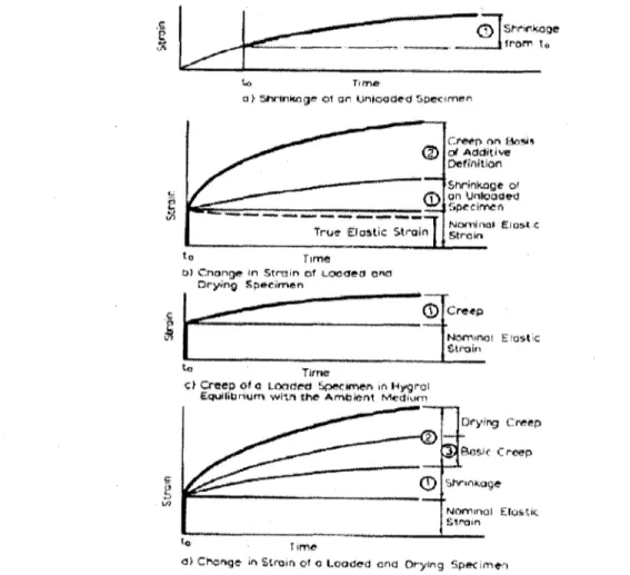
2.3 Creep and Shrinkage of Concrete 20 2.3.1 Classification of Different Types of Time-dependent Strains 20
2.3.2 Theories of Creep of Hardened Cement Paste 24 2.3.3 Factors Affecting the Creep of Concrete 26 2.3.4 Methods of Modelling the Creep of Concrete 32 2.4 Modelling the Deflection Behaviour and Crack Width Evolution of FRP Reinforced
Concrete Beams 36 2.4.1 Theoretical Prediction of Immediate Deflection 36
2.4.2 Theoretical Prediction of Long-term Deflection 38 2.4.3 Deflection Prediction (Immediate and Long-term) in Codes and Guidelines.. 44
2.4.4 Permissible Computed Deflections and Deflection Control (FRP-RC Beams)47 2.4.5 Effect of Sustained Loads on Flexural Crack Width in FRP-RC Beams 50 2.5 Long-term Behaviour of FRP Reinforced Concrete Beams under Sustained Load.. 52
2.5.1 Long-term Behaviour of FRP-RC Beams subjected to 2-point Loading 52 2.5.2 Long-term Behaviour of FRP-RC Beams under Uniform Distributed Load... 57
2.6 Summary 59
CHAPTER 3 CREEP BEHAVIOUR AND RESIDUAL PROPERTIES OF GFRP BARS EXHIBITING DIFFERENT LEVELS OF SUSTAINED
LOAD 61 3.1 Introduction 61 3.2 Research Purpose 66 3.3 Experimental program 66 3.3.1 Materials 66 3.3.2 Study Parameters 67
3.3.3 Fabrication, Instrumentation and Installation of Samples 70
3.3.4 Long-term Monitoring 72 3.4 Results and Discussion 73
3.4.1 Creep Tensile Strain 73 3.4.2 Residual Tensile Properties (Strength and Young's Modulus) 77
3.4.3 Microstructural Analysis 81 3.4.4 Pitfalls in Creep Testing 82 3.5 Summary and Conclusion 84
CHAPTER 4 LONG TERM PERFORMANCE OF DIFFERENT TYPES OF GFRP
BARS UNDER SUSTAINED SERVICE LOAD 86
4.1 Introduction 86 4.2 Research Purpose 86 4.3 Experimental program 86
4.3.1 Materials 86 4.3.2 Study Parameters 91
4.3.3 Fabrication, Instrumentation and Installation of Samples 91
4.3.4 Long-term Monitoring 93 4.4 Results and Discussion 94
4.4.1 Creep Tensile Strain 94 4.4.2 Residual Tensile Properties (Strength and Young's Modulus) 99
4.4.3 Microstructural Analysis 104 4.5 Summary and Conclusion 105
CHAPTER 5 LONG TERM PERFORMANCE OF THIRD-POINT LOADED FRP-REINFORCED CONCRETE BEAMS AFTER ONE YEAR OF
CONTINUOUS LOADING .107 5.1 Introduction 107 5.2 Research Purpose 113 5.3 Experimental Program 114 5.3.1 Materials 114 5.3.2 Sample Description 118 5.3.3 Instrumentation... 118 5.3.4 Sustained Load Frame Calibration and Beam Installation 118
5.3.5 Design of FRP and Steel Reinforced Concrete Members 124
5.3.6 Long-term Test Measurements and Monitoring 125
5.4 Results and Discussion 126 5.4.1 Creep Induced Strain in FRP Reinforcement and Compression Concrete 126
5.4.2 Deflection of Beam Elements 136 5.4.3 Crack Width Evolution for Beam Elements 144
5.5 Conclusions 155
CHAPTER 6 MODELLING THE LONG TERM DEFLECTION OF FULL-SCALE GFRP-REINFORCED CONCRETE BEAMS UNDER UNIFORM
DISTRIBUTED LOAD 157
6.1 Introduction 157 6.2 Research Purpose 159 6.3 Experimental Program 159
6.3.2 Description of Test Specimens 161 6.3.3 Instrumentation and Test Setup Description 162
6.3.4 Design of FRP Reinforced Concrete Members 165 6.3.5 Long-term Test Measurements and Monitoring 166
6.4 Results and Discussion 167 6.4.1 Creep Induced Strain in Compression Concrete and FRP Reinforcement 167
6.4.2 DeflectionofBeam Elements 171 6.4.3 Crack Width Evolution for Beam Elements 182
6.5 Conclusions 188
CHAPTER 7 CONCLUSIONS AND RECOMMENDATIONS 190
7.1 Summary 190 7.2 Conclusions 191
7.2.1 Long-term Performance of GFRP Bars under Axial Sustained Load 191 7.2.2 Long-term Performance of Third-Point Loaded FRP-RC Beams After One
Year of Continuous loading 193 7.2.3 Long-term Performance of Full-Scale FRP Reinforced Beams under Sustained
Uniform Distributed Load for a Six Month Duration 194
7.3 Recommendations for Future Work 196
CHAPTER 8 CONCLUSIONS ET RECOMMANDATIONS 197
8.1 Resume 197 8.2 Conclusions 198
8.2.1 Performance a long terme de barres en PRFV sous charge axiale soutenue.. 198 8.2.2 Performance a long terme des poutres renforcees en PRF avec des charges aux
tiers de la portee pour une duree d'un an sous charge soutenue 200 8.2.3 Performance a long terme des poutres a pleine echelle renforcees en PRFV
sous charge soutenue pour une duree de six mois 202
LIST OF FIGURES
Figure 2.1: Basic material components of an FRP composite (ISIS Canada Educational
Module 2, 2003) 10 Figure 2.2: Stress-strain relationships for fibrous reinforcement and matrix (ISIS Canada
Design Manual No.3 2007) 11 Figure 2.3: Properties of different fibres and typical reinforcing steel 11
Figure 2.4: Schematic of creep strain and recovery strain in polymer 12 Figure 2.5: Tensile creep curves for SMC-R25 polyester laminates (Cartner et al., 1978) 14
Figure 2.6: Comparison of creep curves for (±45) and (90/±45) laminates (Sturgeon 1978).. 15 Figure 2.7: Coupled effect of applied stress and environment on failure mechanism
(schematic) 16 Figure 2.8: Potentially harmful effects of FRP materials in civil engineering application (ISIS
Canada Educational Module 8, 2006) 17 Figure 2.9: Degradation of FRP material due to harsh (alkaline) environmental conditions
(schematic) 18 Figure 2.10: Typical strain history curve during creep deformation (fib 2007) 21
Figure 2.11: Creep and shrinkage strains in concrete subjected to sustained load (Neville,
1996) 23 Figure 2.12: Schematic illustration of the evolution of the deformation of a concrete loaded by
constant sustained load, then unloaded (Byfors, 1980) 24 Figure 2.13: Creep of mortar specimens cured and stored continuously at different humidities.
(Neville, 1959) 27 Figure 2.14: Stress-strain-time relationship. (Riisch, 1960) 28
Figure 2.15: Relation between the creep coefficient and volume/surface (Hansen 1966) 29 Figure 2.16: Creep of concrete cured in fog for 28 days, then loaded and stored at different. 30 Figure 2.17: Flowchart for calculating deformations of GFRP reinforced concrete beams .... 41 Figure 2.18: Moment-curvature (M-K) relation for FRP reinforced concrete (CSA S806-02) 44 Figure 2.19: Average multiplier curves for normal strength concrete (top) and high strength
concrete (bottom) (Gross et al. 2003) 54 Figure 2.20: Comparison of experimental and predicted long-term deflections for two GFRP
Figure 2.21: Longitudinal and side views of concrete beams reinforced with GFRP bars under
sustained load (Vijay and GangaRao 1998) 56 Figure 2.22: Test setup for beams (Arockiasamy et al. 2000) 57
Figure 2.23: Comparison of experimental and predicted deflections for beams B3 (left) and B4
(right) (Arockiasamy et al. 2000) 58 Figure 3.1: University of Sherbrooke FRP durability facility (1) 62
Figure 3.2: University of Sherbrooke FRP durability facility (2) 63 Figure 3.3: Typical strain history curve during creep deformation 64 Figure 3.4: Coupled effect of applied stress and environment on failure mechanism
(schematic) 65 Figure 3.5: GFRP bars 67
Figure 3.6: Specimens ready for installation 70 Figure 3.7: Schematic of bar sustained load frame (magnifying frame) 71
Figure 3.8: Regular levelling of lever arms 12 Figure 3.9: Upper bound creep strain evolution in GFRP-1 bars (above) and GFRP-2 bars
(below) under different sustained load levels 74 Figure 3.10: Residual tensile strength for GFRP-1 bars (above) and GFRP-2 bars (below) after
the 10000 hour duration 78 Figure 3.11: Magnified samples' cross section after exhibiting 10000 hours of loading 81
Figure 4.1: GFRP bars 87 Figure 4.2: Specimens ready for installation 91
Figure 4.3: Sustained load frames comprising GFRP bars 92 Figure 4.4: Magnifying sustained load frame (schematic) 92
Figure 4.5: P-3500 portable strain indicator 93 Figure 4.6: Creep strain evolution for samples at 15 % fu,ave- 9.5 mm GFRP bars (above); 12
mm and 12.7 mm GFRP bars (middle); 15.9 mm GFRP bars (below) 95 Figure 4.7: Creep strain evolution for 9.5 mm GFRP bars (above) at 30 %fu,ave', 12 mm and
12.7 mm GFRP bars at 25 %fu,ave (middle); 15.9 mm GFRP bars at 30 %fu>ave (below) 95 Figure 4.8: Residual tensile strength for samples that exhibited 15 % fu ave (above); Residual
tensile strength for samples that exhibited 25 and/or 30 %fu,ave (below) 99
Figure 4.10: Enlarged samples' cross section after exhibiting 10000 hours of loading under
different sustained load levels 105 Figure 5.1: Moment-curvature (M-K) relation for FRP reinforced concrete (CSA S806-02) 109
Figure 5.2. GFRP bars (left) and CFRP bars (right) examined in the current study 115 Figure 5.3. Typical beam sample instrumentation (left) and cross section (right) 118
Figure 5.4. Schematic of sustained load frame 119 Figure 5.5. Calibration of sustained load frame 120 Figure 5.6. Beams in comprising sustained load frames 121
Figure 5.7,. Long term deflection measurement 126 Figure 5.8. Deformometer (P-3500 Portable strain indicator) for strain measurement 126
Figure 5.9. Creep-strain evolution (Frame 1) of GFRP-1 reinforcement (left) and creep-strain
evolution of concrete (right) . 127 Figure 5.10. Creep-strain evolution (Frame 2) of GFRP-1 reinforcement (left) and creep-strain
evolution of concrete (right) 127 Figure 5.11. Creep-strain evolution (Frame 3) of GFRP-2 reinforcement (left) and creep-strain
evolution of concrete (right) 128 Figure 5.12. Creep-strain evolution (Frame 4) of GFRP-3 reinforcement (left) and creep-strain
evolution of concrete (right) 128 Figure 5.13. Creep-strain evolution (Frame 5) of GFRP-4 reinforcement (left) and creep-strain
evolution of concrete (right) 129 Figure 5.14. Creep-strain evolution (Frame 6) of GFRP-5 reinforcement (left) and creep-strain
evolution of concrete (right) 129 Figure 5.15. Creep-strain evolution (Frame 7) of GFRP-6 reinforcement (left) and creep-strain
evolution of concrete (right) 130 Figure 5.16. Creep-strain evolution (Frame 8) of CFRP-1 reinforcement (left) and creep-strain
evolution of concrete (right) 130 Figure 5.17. Creep-strain evolution (Frame 9) of CFRP-2 reinforcement (left) and creep-strain
evolution of concrete (right) 131 Figure 5.18. Creep-strain evolution (Frame 10) of steel reinforcement (left) and creep-strain
evolution of concrete (right) 131 Figure 5.19: Stress/Strain distribution at a cross-section 134
Figure 5.20. Time dependent deflection (Frame 1 and Frame 2) of GFRP-1 reinforcement
(The result of two sets/pairs) 137 Figure 5.21. Time dependent deflection (Frame 3) of GFRP-2 reinforcement 137
Figure 5.22. Time dependent deflection (Frame 4 and Frame 5) of GFRP-3 reinforcement
(left) and GFRP-4 reinforcement (right) 138 Figure 5.23. Time dependent deflection (Frame 6 and Frame 7) of GFRP-5 reinforcement
(left) and GFRP-6 reinforcement (right) 138 Figure 5.24. Time dependent deflection (Frame 8 and Frame 9) of CFRP-1 reinforcement
(left) and CFRP-2 reinforcement (right) 139 Figure 5.25. Time dependent deflection (Frame 10) of steel reinforced concrete beams 139
Figure 5.26. Time crack width test results for GFRP-1 reinforced beams (The result of two
sets/pairs) 144 Figure 5.27. Time crack width test results for GFRP-2 reinforced beams 145
Figure 5.28. Time crack width test results for GFRP-3 reinforced beams (left) and GFRP-4
reinforced beams (right) 145 Figure 5.29. Time crack width test results for GFRP-6 reinforced beams (left) and GFRP-7
reinforced beams (right) 146 Figure 5.30. Time crack width test results for CFRP-1 reinforced beams (left) and CFRP-2
reinforced beams (right) 146 Figure 5.31. Time crack width test results for Steel reinforced beams 147
Figure 5.32. Typical crack pattern for FRP reinforced concrete beams at three time intervals
(GFRP-5) 150 Figure 5.33: Crack width growth over 1 year of sustained loading 151
Figure 5.34: Crack width growth over one year of sustained loading as a multiple of initial
crack width 151 Figure 5.35: Measured versus calculated initial crack widths using various fa values 152
Figure 5.36: Measured versus calculated initial crack widths using fa values (1.4 and 1.6). 153 Figure 5.37: Measured versus calculated crack widths after one year using optimal fa and kt
values 154 Figure 5.38: Calculated bond coefficient kb for the different types of FRP reinforcement... 154
Figure 6.2: Reinforcement details of the beams 162 Figure 6.3: Reinforcement cages prior to casting 163 Figure 6.4: Transportation of concrete blocks to laboratory 163
Figure 6.5: Forklift truck loading blocks on beams 163 Figure 6.6: Instrumented beams under uniform sustained block load 164
Figure 6.7: Deformometer (P-3500 Portable strain indicator) for strain measurement 166 Figure 6.8: Crack detection and crack width measurement (high precision microscope) 166 Figure 6.9: Data acquisition system; LVDT connected to data acquisition system 167 Figure 6.10: Strain evolution for FRP reinforcement at midspan for beams A, B, C and D.. 168
Figure 6.11: Creep-strain evolution of compression concrete for beams A, B, C and D 169
Figure 6.12: The stress strain distribution at a cross-section 170
Figure 6.13: Deflection results for all beams 172 Figure 6.14: Moment-curvature (M-K) relation for FRP reinforced concrete 174
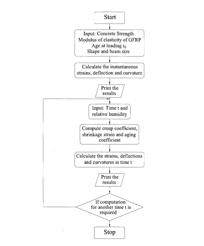
Figure 6.15: Flowchart for calculating the deformations of GFRP-RC beams 176 Figure 6.16: Experimental versus empirical and numerical deflection results (Beam A) 179
Figure 6.17: Experimental versus empirical and numerical deflection results (Beam B) 179 Figure 6.18: Experimental versus empirical and numerical deflection results (Beam C) 180 Figure 6.19: Experimental versus empirical and numerical deflection results (Beam D) 180
Figure 6.20: Maximum crack width evolution for beams A, B, C and D 182 Figure 6.21: Crack propagation pattern after 1 month, 3 months and 6 months (Beam A)... 183
Figure 6.22: Crack propagation pattern after 1 month, 3 months and 6 months (Beam B)... 183 Figure 6.23: Crack propagation pattern after 1 month, 3 months and 6 months (Beam C)... 184 Figure 6.24: Crack propagation pattern after 1 month, 3 months and 6 months (Beam D)... 184
Figure 6.25: Crack width growth over 6 months of sustained loading 185
Figure 6.26: Measured versus calculated initial crack widths 187 Figure 6.27: Measured versus calculated crack widths after 6 months of sustained load 187
LIST OF TABLES
Table 2.1: Maximum allowable stress in FRP bars (CAN/CSA S6-06) 19 Table 2.2: FRP-reinforcement creep rupture stress limits (ACI 440.1R-06) 19 Table 2.3: FRP-reinforcement creep rupture stress limits (CNR-DT 203/2006) 19 Table 2.4: Sustained stress limits as a percentage of design strength (fib Bullettin 40) 20
Table 2.5: Maximum deflection formulas using the deflection approach (ISIS Canada Design
Manual 2007) 45 Table 2.6: Values for coefficients ft and m (Eurocode 2 and Model Code 1990) 47
Table 2.7: Recommended minimum thickness of non-prestressed beams or one way slabs... 47
Table 2.8: Maximum permissible computed deflections 48 Table 3.1: Mechanical properties of the two types of GFRP as provided by manufacturer and
as obtained through tensile tests 69 Table 3.2: GFRP-1 creep-test details (15 %, 30 %, 45 % and 60 %/H,a w) 75
Table 3.3: GFRP-2 creep-test details (15 %, 30 % and 45 %fu,me) 76
Table 3.4: GFRP-2 creep-test details (60 %/„,ave) 76
Table 3.5: Residual tensile property results for GFRP-1 samples 79 Table 3.6: Residual tensile property results for GFRP-2 samples 80 Table 4.1: Physical properties of the six types of GFRP bars 88 Table 4.2: Mechanical properties of the tested GFRP bar-types indicated by manufacturers. 89
Table 4.3: Mechanical properties of the tested GFRP bar-types obtained from tensile tests... 90
Table 4.4: Creep-test details of GFRP bars subjected to 15 %fu,ave- (Group 1) 97 Table 4.5: Creep-test details of GFRP bars subjected to 25 % and 30 % fUiave. (Group 2) 98
Table 4.6: Residual tensile property results for 15 %fUiave. (Group 1) samples 100 Table 4.7: Residual tensile property results for 25 % & 30 % fu,ave (Group 2) samples 102
Table 5.1. Physical properties of FRP bars (GFRP and CFRP)* 116 Table 5.2. Mechanical properties of FRP bar-types as obtained from tensile tests 117
Table 5.3. Tested concrete beams and relevant details 122 Table 5.4. Details on strain evolution within reinforcement 132 Table 5.5. Details on strain evolution of top concrete fibre 133 Table 5.6: Experimentally obtained initial deflection and long-term deflection values 140
Table 5.7: Theoretical calculation of immediate deflections using different approaches 141 Table 5.8. Long-term deflection results compared North American standard predictions.... 143
Table 5.9: Average crack widths for tested beams 149 Table 5.10: Average calculated kb bond coefficient for the different types of FRP bars 155
Table 6.1: Mechanical properties of the reinforcing bars 160
Table 6.2: Physical properties of GFRP bars 161 Table 6.3: Test specimens and relevant details 164 Table 6.4: Details on creep strain evolution within reinforcement (at mid-span) 168
Table 6.5: Details on creep strain evolution of compression concrete (at mid-span) 169 Table 6.6: Comparison between strain increase due to flexural loading and axial sustained
load 171 Table 6.7: Immediate deflections (experimental results versus theoretical predictions) 175
Table 6.8: Comparison of long-term deflection results with ACI 440.1R-06 and CAN/CSA
S806-02 predictions 175 Table 6.9: Average crack widths for tested beams 185
NOMENCLATURE
a Depth of equivalent rectangular stress block, (mm) Ac Area of concrete in compression (mm2)
A ' Area of the age-adjusted transformed section (mm ) b Widths of rectangular cross section, (mm)
P The ratio of the distance from the neutral axis to extreme tensile fibre and distance from neutral axis to centre of the tensile reinforcement =
(h - c)/(d - c)
Pd Reduction factor used in calculating deflection
c Distance from extreme compression fibre to neutral axis, (mm)
Ce Environmental reduction factor for various fibre type and exposure
conditions.
d Distance from extreme compression fibre to centroid of tension
reinforcement, (mm)
dc Thickness of concrete cover measured from extreme tension fibre to centre of bar or wire location closest thereto, (mm)
Ec Modulus of elasticity of concrete, (MPa)
Ee Age-adjusted effective modulus
Ef Design or guaranteed modulus of elasticity of FRP defined as mean
modulus of sample of test specimens (E/= E/,ave), (MPa)
Efiave Average modulus of elasticity of FRP, (MPa)
Es Modulus of elasticity of steel, (MPa)
Ec Modulus of elasticity of concrete, (MPa)
E'c(t, t0) Age adjusted modulus of elasticity of concrete, (MPa)
£f efrp,0 Zfu £ fu £cu £cs Ei ER £u,ave
Strain in FRP reinforcement, (microstrains)
Initial strain in FRP due to sustained load, (microstrains) Design rupture strain in FRP reinforcement, (microstrains) Guaranteed rupture strain in FRP reinforcement (microstrains) Creep strain, (microstrains)
Ultimate strain in concrete, (microstrains) Shrinkage strain, (microstrains)
Initial strain, (microstrains)
Strain in reinforcement, (microstrains)
f Concrete compressive strength, in (MPa) ff Stress in FRP reinforcement in tension, (MPa) f fs Creep rupture stress limit, (MPa)
fu.ave Average ultimate tensile stress, (MPa) fju Design tensile stress, (MPa)
f fu Guaranteed tensile stress, (MPa)
h Height of beam cross section, (mm)
/ ' Moment of inertia of a the age adjusted transformed section using the modular ratio 77'(t, t0) , (mm4)
Ic Moment of inertia of a the concrete about the centroid after age
adjustment, (mm4)
ICr Moment of inertia of a cracked transformed concrete section, (mm4)
Ie Effective moment of inertia, (mm4)
Ig Moment of inertia of a gross uncracked concrete section, (mm4)
kb Bond-dependent coefficient
kt Multiplier to account for crack width increase with time L Length of span (between two supports) (mm)
m Modular ratio for reinforcement, (Efrp/ Es) Ma Maximum actual applied moment, (KN.m)
Mcr Cracking moment, (KN.m)
Mcr Nominal moment capacity, (KN.m) M ^ Moment due to sustained load, (KN.m) rif Modular ratio between FRP and concrete
RH Relative humidity
s Spacing between reinforcement (mm)
w Crack width (mm)
yc Distance between centroids of the effective concrete area and the age-adjusted transformed area, (mm)
dcp+sh Additional deflection due to creep and shrinkage, (mm) Aj Initial deflection, (mm)
(A ,')SUs Initial deflection due to sustained load, (mm)
(A/l)max Limiting deflection-span ratio
4>(t,to) Creep coefficient
<pcorr Correction factor for creep coefficient (p. Creep coefficient at time t
ri'(t, t0) Modular ratio of modulus of elasticity of GFRP to the age adjusted
modulus of elasticity of concrete
p Reinforcement ratio p' Upper reinforcement ratio
Pf ip/rp) Reinforcement ratio of FRP
X Long-term deflection multiplier
if/ Curvature (rad)
X (1,1.) Aging coefficient function; % = 0.8 is normally used for concrete £ Time dependent factor for computing deflection
CHAPTER 1
INTRODUCTION
1.1 Background and Problem Definition
Fibre reinforced polymer (FRP) materials are gaining wider acceptance for use as primary reinforcement in concrete structures. Due to its high strength and non corrosive nature, FRP provides an alternative to steel reinforcement. The use of FRP as structural reinforcement, in turn, provides the potential advantage of lowered maintenance costs and extended service life for several types of structures, including bridge deck slabs, abutments, walls and other structures exposed to corrosive environments (Gross et al. 2003). In the past two decades, an abundance of research has taken place on fibre reinforced polymer reinforced concrete (FRP-RC). A better understanding is how available on paramount characteristics such as strength, stiffness, bending, shear and FRP-concrete bond.
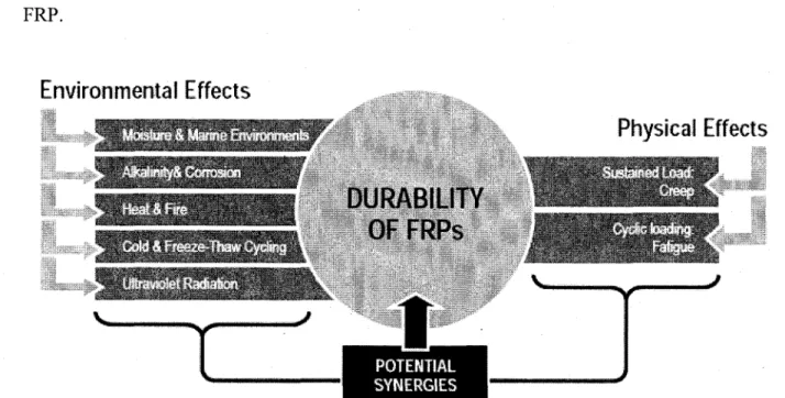
Nevertheless, the area of durability of FRP remains needy for information; mainly due to the time consuming nature and/or costly equipment necessary for durability experiments. The ISIS Canada Durability Monograph (2006) defines durability for FRP as "the ability of an FRP element to resist cracking, oxidation, chemical degradation, delamination, wear and/or the effects of foreign object damage for a specified period of time, under specified loading conditions". As regards the durability of FRP materials, the commonly known adversities can be categorized under two branches, physical effects and environmental effects. The former includes sustained load (creep) and fatigue, whereas the latter includes moisture, alkalinity, fire, freeze-thawcycles and UV rays. The negative influence on an FRP bar can be due to a combination of any of the former adversities. Sustained load (creep), however, remains a common aspect in most if not all FRP reinforced structures; the typical purpose of designing such structures is to withstand sustained load and resist deterioration.
Under sustained load, FRP bars suffer plastic (permanent) deformation, typically occurring under unfavourable environments over a long time. This phenomenon is what is commonly referred to as "Creep". Creep typically increases the long term deflection of FRP reinforced
concrete elements and may, under certain circumstances, cause catastrophic failure. Despite its higher tensile strength over conventional steel, FRP exhibits less tensile and shear stiffness. As a result of the relatively lower axial stiffness of the FRP bars, FRP reinforced concrete members deform more than their steel reinforced counterparts. Consequently the design of FRP reinforced concrete members is predominantly governed by serviceability requirements (Gaona 2004). Thus, allowable deflections and cracking govern the design of FRP reinforced concrete elements, particularly GFRP reinforced concrete elements.
In 2003, a protocol was set to remedy this lack-of-information drawback, where seven subcommittees were assembled; each of which is to focus on a particular FRP adversity (Karbhari et al. 2003). Research priority was given to the following seven conditions: moisture/solution, alkali, thermal (including temperature cycling and freeze-thaw), creep, fatigue, ultraviolet, and fire. For this study the creep phenomenon within FRP bars was chosen; the aforementioned synopsis ranks this phenomenon as highly critical yet the relevant data, to date, is sparse and questionable. Despite continuous research, the information content regarding this issue did not increase significantly.
Furthermore, it has become a necessity to ratify standard test methods by which the international research community can recommend to civil engineers to use as a basis for selecting the FRP rebar appropriate for a certain application. With more manufacturers getting into the FRP-production industry, certifying such products according to the sought standard test methods is also of great importance.
1.2 Objectives and Originality
Having mentioned that the information content associated with the long-term behaviour of FRP reinforced concrete under sustained load is scarce, the main objective of this study is to further the knowledge in this particular research domain. The long-term behaviour of the material, itself, under sustained load and the overall long-term behaviour of the concrete element comprising FRP bars are the main focus of this study.
1 To perform a critical review on the available contributions related to the study of FRP creep due to imposed stress and adverse environmental conditions. A similar review is necessary regarding the long-term deflection, strain variation and crack width evolution of FRP-reinforced concrete members.
2 To conduct long-term (creep) experiments on the currently available commercial FRP bars under different sustained load levels. Through the obtained information, the available codes and guidelines can be modified or confirmed appropriate as regards the indicated creep rupture stress limits.
3 Long-term (creep) data for FRP bars is inherently noisy; means of ameliorating FRP creep tests are necessary.
4 To study the performance of FRP-reinforced concrete beams under sustained load for long-term duration, in terms of serviceability; there is yet a lack of information for different types of sustained load and different types of commercial bars.
5 To calibrate and compare between the models available on immediate and long-term deflection of FRP-reinforced beams in light of the data obtained. Numerical modelling is to be conducted to gain insight into the mechanism beyond the long-term behaviour of an FRP reinforced concrete section.
1.3 Methodology
To achieve the aforementioned objectives, an extensive experimental program, followed by microstructural analysis as well as empirical and numerical modelling, was conducted. The experimental program included the preparation, installation and long term monitoring of 99 GFRP bar samples and 24 FRP reinforced concrete beams. The materials^ testing frames and instrumentation, used for this study are mentioned below:
1 Materials:
(i) GFRP-1: Sand-coated glass FRP bars of diameter = 9.5 mm and fibre content ratio = 56.8 % by volume.
(ii) GFRP-2: Helically wrapped sand-coated glass FRP of diameter = 9.5 mm and fibre content ratio = 50.6 % by volume.
(iii) GFRP-3: Sand-coated glass FRP bars of diameter = 12.7 mm and fibre content ratio = 64.5 % by volume.
(iv) GFRP-4: Ribbed glass FRP bars of diameter = 12 mm and fibre content ratio = 75.2 % by volume.
(v) GFRP-5: Sand-coated glass FRP bars of diameter = 15.9 mm and fibre content ratio = 66.6 % by volume.
(vi) GFRP-6: Helically wrapped sand-coated glass FRP of diameter = 15.9 mm and fibre content ratio = 57.5 % by volume.
(vii) CFRP-1: Sand-coated carbon FRP bars of diameter = 9.5 mm and fibre content ratio = 73.6 % by volume.
(viii) CFRP-2: Helically wrapped (textured) carbon FRP of diameter = 9.5 mm (ix) Conventional 15 M steel of diameter = 1 6 mm.
(x) Conventional 10 M steel of diameter = 11.3 mm.
(xi) Ordinary concrete with a target concrete compressive strength = 35 MPa.
2 Means of maintaining sustained load:
(i) Three series of bar sustained load frames: Series 1 contains 20 frames of inner clear height = 1206 mm; Series 2 contains 24 frames of clear height = 1486 mm; Series 3: contains 20 frames (in heating tunnel) with a clear height of 1486 mm.
(ii) Beam sustained load rigs: Ten sustained load rigs, each with the capacity of two mirror beams of dimensions (100 m x 150 mm x 1800 mm)
(iii) Four full-scale beams: Steel supports and concrete blocks (of dimensions 610 mm x 762 mm x 1219 mm and weight = 13334 kN) to simulate sustained uniform distributed load.
3 Instrumentaion:
(i) A data acquisition system comprising 60 ports connected to strain gauge wires for regular strain measurement.
(iii) Electrical strain gauges of 10 mm length and 120 ohm resistance manufactured by Kyowa limited.
(iv) Electrical strain gauges of 67 mm length and 120 ohm resistance manufactured by Kyowa limited.
(v) A high precision vernier caliper for deflection reading.
(vi) Demec points to be fixed on concrete beams to serve as references for deflection reading.
(vii) A high precision microscope for crack width reading.
4 Analysis:
(i) Numerical (finite difference) modelling is performed using a Fortran-2003 environment, using a system of equations (based on the age-adjusted effective modulus method).
(ii) Empirical (simplified) equations are developed through regular linear or non-linear regression using Microsoft Excel.
1.4 Structure of the Thesis
The thesis comprises eight chapters, four of which (Chapters 3 to 6) represent stand-alone studies that include their own literature review, set of objectives, results, analysis, discussion and conclusion. A portion of information may be repeated in more than one chapter to give each chapter/study an independent sense and convenience for the reader. The chapters are interdependent, serving together towards the goal of better understanding the long term behaviour of FRP reinforced concrete. The following is a brief description of each chapter's content:
Chapter 1: This chapter includes (i) the background and problem definition of the thesis, (ii) research objectives and originality, (iii) methodology and (iv) thesis structure.
Chapter 2\ In this chapter, a detailed literature review is conducted on (i) the creep behaviour of materials comprising FRP-RC (i.e., FRP reinforcement and concrete) and the factors
affecting them; (ii) the theoretical models available regarding immediate and long-term deflection of FRP-RC beams; (iii) previous efforts related to the topic of long-term deflection of FRP-RC beams. Selected parts of this literature are made available, within chapters 3 to 6, to provide convenience for the reader while going through the material of this thesis.
Chapter 3 : The creep behaviour and susceptibility to creep rupture of two types of GFRP bars is studied. Different levels of sustained axial load are applied to 37 GFRP samples. Regular monitoring of the creep strain evolution of the bars took place over a 10000 hour (417 days) duration. This was followed by residual tensile tests and microstructural analysis. The creep coefficient of GFRP bars was calculated.
Chapter 4\ The creep behaviour of six different types of GFRP bars was studied under two levels of allowable service load, according to the currently available North American standards. The test duration, for the two phases, exceeded 10000 hours (417 days) wherein regular monitoring of creep strain evolution took place and the creep coefficient of GFRP bars was calculated. This was followed by residual tensile tests and microstructural analysis. The creep coefficient of GFRP bars was calculated.
Chapter 5: The long term performance of twenty concrete beams (ten pairs) comprising GFRP, CFRP, and steel reinforcing bars was studied in terms of deflection, strain increase and crack width evolution. The beams of dimensions 100 mm x 150 mm x 1800 mm were installed under third-point concentrated load, for a period exceeding one year. Exhibiting a maximum applied moment of 25 % of their nominal moment capacity, Mn, all beams were
regularly monitored for the one-year duration. Theoretical predictions for immediate deflection were calculated and compared to the obtained experimental results. The long-term to immediate deflection ratio, 2, was calculated for all beams and compared to ACI 440.1R-06 and CAN/CSA S806-02 predictions.
Chapter 6. Four full-scale GFRP reinforced concrete beams, of dimensions (215 mm x 400 mm x 4282 mm) were subjected to uniform distributed load for a period of six months. The main study parameters are (i) bottom reinforcement ratio and (ii) type of upper/compression
reinforcement (GFRP and/or steel). The maximum applied moment ranged from 15 to 21 % of the nominal moment capacity for the beams. Numerical modelling took place using a computer program (Fortran-2003) based on the age-adjusted effective modulus method, to predict the long-term deflection of the beams. The creep and shrinkage coefficients were calculated based on ACI Committee 209 recommendations (1992) and CEB-FIP Model Code (1990). The theoretical curves using different empirical models (available in CSA A.23.3-04 and ACI 318-08) as well as the numerical models mentioned above were compared to the measured values.
Chapter 7: This chapter contains the overall conclusion for all previous chapters. Recommendations are proposed for subsequent research studies in the same domain.
Chapter 8: This chapter contains the overall conclusion for all previous chapters (in the French language). Recommendations are proposed for subsequent research studies in the same domain.
CHAPTER 2
LITERATURE REVIEW
2.1 BackgroundIn the past two decades, an abundance of research has taken place on fibre reinforced polymer reinforced concrete (FRP-RC). Due to that, a better understanding is now available on paramount characteristics such as strength, stiffness, bending, shear and FRP-concrete bond. While the behaviour of steel reinforced concrete beams under sustained loads has been studied for nearly half a century, the area of long-term/creep behaviour of FRP reinforced concrete beams remains barely touched. This is mainly due to the time consuming nature of creep experiments. The sought knowledge - of long-term serviceability aspects - is extremely important for the infrastructure facilities constructed using FRP.
It is commonly known that concrete creep, shrinkage and other factors contribute to the increase of strain, curvature, and deflection over time. For conventional reinforced concrete, steel reinforcement acts to restrain these effects. On the other hand, FRP reinforcement with its lower modulus of elasticity and higher susceptibility to creep may be a concern for its comprising concrete members, as regards serviceability. Whether it be steel or FRP reinforcement, the concrete cross section exhibits strain in concrete within the compression zone due to creep. This, in turn, leads to an increase in neutral axis depth and redistribution of stresses between the concrete and reinforcement (ACI 435, 2003). Associated with the latter time-dependent behaviour, is an increase in curvature. This curvature increase, along with the formation of additional flexural cracks over time, leads to increase in beam deflection.
In this chapter, a thorough literature review is provided on all aspects that lead to a better understanding of the aforementioned time dependent behaviour of FRP-RC beams under sustained flexural load. The main topics addressed in this literature-review chapter are (i) the creep behaviour of FRP bars (comprising fibres and polymer matrix); (ii) the creep behaviour of concrete; (iii) the creep-rupture stress limits made available by commonly used codes and guidelines; (iv) the long-term behaviour of FRP-RC beams under sustained load and finally (v) the theoretical (empirical and numerical) methods of prediction available in codes and
guidelines. Nevertheless, every chapter in this study serves as a stand-alone project containing its relevant literature. This provides convenience for the reader who seeks the information content of a particular portion of this study.
2.2 Creep of FRP Composites and FRP Components
Creep of a bar is defined as the increase in length of a bar loaded with a constant force over time, beyond the initial (elastic) deformation (Gere and Timoshenko 1990). In this section a brief review is presented on the properties of FRP materials, in general, as well as the properties of the individual components of FRP bars. The creep of the polymer (matrix) will be emphasized upon as well as the creep of the FRP bars and the relevant influencing factors. The tensile strength of FRP is known to exceed that of steel. Nevertheless, the stiffness of FRP is lower than the stiffness steel. FRP materials behave essentially linearly until fracture when loaded along the fibre direction, and thus FRP is brittle by nature. For many fibre reinforced polymers, the thermal expansion coefficients are much lower than those of metals. Thus, composite structures may exhibit better dimensional stability over a wide range of temperatures. Non-corroding behaviour is another major advantage attributed to FRP composites. Nevertheless, a disadvantage for many polymeric matrix composites is their moisture-absorbing nature, from their surrounding environment. This induces adverse internal stresses within the material and creates dimensional changes.
2.2.1 Composition of FRP Materials
In simple terms, composites are a combination of two or more non homogeneous materials that do not chemically interact. This combination creates a new material that exhibits better properties than the individual components. The combination of fibre and resin in FRP bars yields a reinforcement of higher tensile strength than that of steel. Nevertheless, unlike steel, FRP composites are non-isotropic, since they depend on the orientation of the fibres and the applied load relative to the fibre orientation.
FRP materials can be classified into three main types (unidirectional, bidirectional, and bi-directional). Unidirectional FRP is the most popular and defines most of the commercial FRP bars available. FRP composites, in general, consist of two or more distinct physical phases;
the fibrous phase impregnated in a continuous matrix phase (See Figure 2.1). The fibres carry the load while the surrounding matrix (the resin) acts as a load transfer medium between the fibres and keeps them in the desired location/orientation; the resin also protects the fibres from abrasion and environmental damage (chemicals and humidity). Figure 2.2 shows the stress-strain relationship of the individual components of fibres, resin and the overall stress-stress-strain behaviour of FRP material.
F I B R E S P O L Y M E R FRP MATRIX
Figure 2.1: Basic material components of an FRP composite (ISIS Canada Educational Module 2, 2003)
2.2.1.1 Fibres
The most commonly used fibres in the civil engineering domain are carbon, aramid, and glass. There are two types of carbon fibres. The first type is of high resistance (3000 to 5000 MPa), whereas the second has a high modulus of elasticity (400 GPa) (See Figure 2.3). Aramid fibres have very high stress at rupture, yet the use of this type is limited due to its low resistance in compression and shear. This is attributed to the poor adherence between the fibre and the matrix. All three types of fibres have very good creep properties and their mechanical properties can be maintained for a temperature range that varies from 50°C to 300°C. Glass fibres are the most commonly used and emphasized upon in research due to their lower cost. Combinations/hybrids of glass fibres and carbon or aramid fibres are used, in certain applications, to increase the stiffness of a structural member.
Figure 2.2: Stress-strain relationships for fibrous reinforcement and matrix (ISIS Canada Design Manual No.3 2007)
Strain (%]
Figure 2.3: Properties of different fibres and typical reinforcing steel.
2.2.1.2 Resins
Thermoplastics and thermosets are the two main types of polymers used for resins. For the former, the resin molecules contain rigid aromatic rings yielding them a relatively high glass transition temperature (Tg), and dimensional stability at high temperatures. Thermosetting
industry. Thermosetting resins (vinylester, epoxy and phenolic resins) are less viscous than thermo-plastic resins (polypropylenes, nylon, polycarbohydrates, etc.).
2.2.1.3 Fillers and Additives
A polymeric matrix (the resin) may have fillers added to enhance its properties. Some of the main advantages of filler addition are (i) increasing the modulus of elasticity, (ii) reducing cost, (iii) reducing mould shrinkage, (iv) controlling viscosity and (v) producing smoother surface. One of the most commonly used fillers is Calcium carbonate (CaCOs). It is used for polyester and vinylester for reduction of cost as well as mould shrinkage.
2.2.2 Creep of Resin (polymer matrix)
The typical long-term (creep) behaviour of polymers under sustained load is shown in Figure 2.4. This behaviour is influenced by a variety of factors elaborated upon in the following sub-section.
A
Constant Stress 60 C .S ' 1 3_ •5 ca O g_ J 5' era TimeFigure 2.4: Schematic of creep strain and recovery strain in polymer
Since a considerable magnitude of creep may occur at low temperatures, the creep of polymers is considered a vital area. The creep of polymers is a function of temperature and
stress level. Creep is a result of viscoelastic deformation (the combination of elastic deformation and viscous flow). As shown in Figure 2.4, creep strain exhibits nonlinear increase with time. Nevertheless, the elastic deformation is immediately recovered when the stress is waived. The accumulated deformation due to viscous flow recovers asymptotically to a value called recovery strain. For non-reinforced polymers, large creep strain may take place at room temperature and at low stress levels. The creep phenomenon becomes more critical at elevated temperature or high stress levels. The commercial reinforcing bars, however, do not exhibit significant creep strain. Nevertheless, aramid fibres and glass fibres have a greater susceptibility to creep rupture at lower stress levels than carbon fibres (Chiao and Moore
1971).
2.2.3 Factors Affecting the Creep of FRP
The creep behaviour of FRP bars is a function of several factors; the most influential are presented below.
2.2.3.1 Sustained-load Magnitude
The polymeric behaviour of FRP bars is highly dependent on the loading magnitude. When the magnitude is high, the behaviour of the reinforced polymer is rigid and adopts a brittle manner; the sample may rupture in a short period of time (eg., the rupture of a GFRP bar under high sustained tensile stress). Nevertheless, the same specimen may exhibit a ductile manner and show high toughness values when the applied load is low in magnitude. The creep behaviour of an FRP bar under uniaxial stress can be expressed by the following creep compliance equation:
a (2.1) where s (t) is the measured strain at time t and o is constant stress level in a creep experiment.
In Figure 2.5, it is obvious how the rate and magnitude of creep increases when the applied load increases, for identical SMC-R25 laminates tested at room temperature.
TIME ( W I N . )
Figure 2.5: Tensile creep curves for SMC-R25 polyester laminates (Cartner et al., 1978)
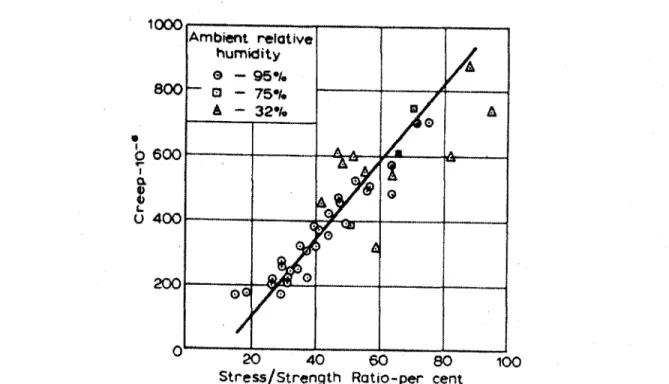
Gaona (2003) and Youssef et al. (2008) have conducted creep behaviour experiments on a variety of GFRP bars for lengthy periods. The former study concluded that the creep strain increase for three different types of 15.9 mm GFRP bars, subjected to sustained load levels ranging from 23 to 27 % fUiave, is in the order of 2 to 6.6 % of initial elastic strain SfrP,o', surrounding environment was controlled at (31°C and 67 % relative humidity) for a test duration of six months. Showing fair agreement, the latter study (Youssef et al. 2008) yields creep strain values that range from 2 to 8.7 % efrp.o for two types of 9.5 mm commercial GFRP bars; the test duration ranged from 4000 to 8600 hours (5.5 to 12 months approx.); sustained load levels ranged from 15 to 45 % fu,av e at standard laboratory atmosphere (23 ± 3 °C and 50
± 10 % relative humidity).
Studies such as that of Budelman & Rotasy 1993 indicate that if sustained stress is less than 60 % of the average ultimate tensile strength (fu,ave), creep rupture is less likely to occur.
Greenwood (2002), however, deduced through series of creep-rupture testing that the creep stress limit of two types of 6.4 mm GFRP rods, in air at 23 °C, is approximately 45 %/„,ave for
(2008) as well as the findings of the study at hand, where two commercial GFRP bars were tested in similar surrounding environmental conditions. It was realized that there is no sign of creep rupture at 45 % fu,ave\ a realization confirmed by microstructural analysis. On the other
hand, rupture susceptibility is evident on exhibiting 60 %fu,ave, at different endurance times.
2.2.3.2 Fibre Content and Fibre Orientation
Since fibres barely exhibit creep under relatively high loads, the abundance of fibres in an FRP bar significantly decreases deformation under sustained load. Nevertheless, when an FRP sample is low in fibre content or the load is applied transversally to the fibres, the creep phenomenon is more pronounced. With the increase of stress level, temperature and time, creep compliance increases. Creep is also a function of the fibre orientation. For unidirectional fibres (of orientation angle 0 = 0) creep compliance is nearly constant; creep in the longitudinal direction of a unidirectional laminate, roving or bar is insignificant. Nevertheless, for other fibre orientation angles, creep strain can be significant. In multidirectional FRP rovings, creep depends on the construction of the element.
Figure 2.6: Comparison of creep curves for (±45) and (90/±45) laminates (Sturgeon 1978)
The creep-strain magnitudes vary noticeably when using (±45) versus (90±45) oriented fibres (Figure 2.6); this is despite the fact that the mechanical properties of the two rovings are almost equal. The addition of 90° layers to a ±45° construction causes restraint to the rotational tendency of ±45° fibres towards the direction of loading direction, reducing creep
2000
0 1 10 130 1000
strain significantly. This concludes that fibre orientation has an impact on the creep properties of FRP laminates. Nevertheless, creep behaviour is governed by the fibres when aligned with the loading direction, (Dootson 1972).
2.2.3.3 Environmental Effects
Environmental effects may have a serious impact on the durability of FRP composites, especially when coupled with sustained or cyclic loading. The durability of FRP is defined by Karbhari et al. (2003) as the ability of an FRP element to resist cracking, oxidation, chemical degradation, delamination, wear and/or the effects of foreign object damage for the specific period of time under the appropriate load conditions, under specified environmental conditions. Figure 2.8 illustrates all adverse environmental and physical effects that may harm an FRP element. The potential harm may be a combination of two or more adversities (See Figure 2.7).
Figure 2.7: Coupled effect of applied stress and environment on failure mechanism (schematic)
Environmental factors such as high temperature, temperature fluctuation, high humidity, corrosive fluids and water absorption can adversely affect the behaviour of some polymer composites. Moisture (water absorption) can reduce the strength and stiffness of some polymeric composites by as much as 30 % compared to the original dry material. Water absorption breaks down the interface between the reinforcing fibre and resin matrix leading to