HAL Id: hal-01360864
https://hal.archives-ouvertes.fr/hal-01360864
Submitted on 15 Sep 2016
HAL is a multi-disciplinary open access
archive for the deposit and dissemination of
sci-entific research documents, whether they are
pub-lished or not. The documents may come from
teaching and research institutions in France or
abroad, or from public or private research centers.
L’archive ouverte pluridisciplinaire HAL, est
destinée au dépôt et à la diffusion de documents
scientifiques de niveau recherche, publiés ou non,
émanant des établissements d’enseignement et de
recherche français ou étrangers, des laboratoires
publics ou privés.
Duy-Huy Nguyen, Hang Nguyen, Eric Renault
To cite this version:
Duy-Huy Nguyen, Hang Nguyen, Eric Renault. A new Channel-and QoS-Aware Scheduling Scheme
for Real-time Services in LTE Network. International Journal of Applied Information Systems, 2016,
11 (4), pp.8. �10.5120/ijais2016451601�. �hal-01360864�
A new Channel- and QoS-Aware Scheduling Scheme
for Real-time Services in LTE Network
Duy-Huy Nguyen
SAMOVAR, T ´el ´ecom SudParis, CNRS,Universit ´e Paris-Saclay
9 rue Charles Fourier - 91011 Evry Cedex
Hang Nguyen
SAMOVAR, T ´el ´ecom SudParis, CNRS, Universit ´e Paris-Saclay
9 rue Charles Fourier - 91011 Evry Cedex
´
Eric Renault
SAMOVAR, T ´el ´ecom SudParis, CNRS, Universit ´e Paris-Saclay
9 rue Charles Fourier - 91011 Evry Cedex
ABSTRACT
This paper proposes a new scheduling scheme which is based on Channel- and QoS-Aware for real-time traffics in LTE down-link direction. The real-time services (VoIP, Video, etc.) are very sensitive to network impairments such as delay, packet loss, jit-ter, etc. The proposed scheduling scheme considers Maximum Queue Size (MQS) as an essential factor for the priority metric and the combination of well-known M-LWDF-based algorithms such as M-LWDF, VT-MLWDF and Queue-HOL-MLWDF. The simulation results show that the proposed scheme has the per-formance which not only satisfies QoS requirements of real-time services but also outperforms the M-LWDF, VT-MLWDF and Queue-HOL-MLWDF schedulers in terms of Packet Loss Rate (PLR), cell throughput, Fairness Index (FI) and Spectral Efficiency (SE), especially for Video flow. The proposed sched-uler also significantly improves the delay in comparison with the VT-MLWDF and Queue-HOL-MLWDF schedulers ones for both VoIP and Video flows. The performance evaluation is com-pared in terms of Delay, PLR, Throughput, FI and SE for M-LWDF, VT-MM-LWDF, Queue-HOL-MLWDF and the proposed schedulers.
Keywords
Scheduling Algorithm, Resource Allocation, Real-time Services, LTE, QoS
1. INTRODUCTION
The Long Term Evolution (LTE) is developed by the Third Gen-eration Partnership Project (3GPP) [1]. It is a mobile network which has high data rate, low delay and fully packet-based. This means to improve the capability of legacy system by increasing data rates and extending superior QoS for various multimedia applications. Basic components of LTE network include a pow-erful eNodeB (eNB) station and several User equipments (UEs) in addition to a gateway [5]. The eNB station combines with core network through several standard complicated protocols. Basic packet scheduling is carried out by the network operator in both UE and eNB station for both uplink as well as downlink. How-ever, according to the 3GPP, there are no firm specifications for scheduling technique in LTE network. One of the most important modules of packet scheduling is Radio Resource Management (RRM) which decides users that would transmit their data on the air interface. The packet scheduling should integrate fairness in
terms of throughput as well as the service policies to which users subscribe [4].
LTE architecture defines a complete table with packet delay budget and packet loss rates for performing different service class in the network [1] which some or all may be executed by service provider. This table divides resource types in the LTE network into two groups, those are Guaranteed Bit Rate (GBR) and Non-GBR. In order to meet different QoS require-ments for these groups, several packet scheduling algorithms have been proposed. According to [7], the scheduling strate-gies for LTE downlink are divided into five groups including: (1) Channel-unware strategies, (2) Channel-aware/QoS-unaware strategies, (3) Channel-aware/QoS-aware strategies, (4) Semi-persistent scheduling for VoIP support, and (5) Energy-aware strategies. For the real-time services such as VoIP, Video, etc. which are very sensitive to delay and PLR. So that, the Channel-aware/QoS-aware strategies are very essential for them. Several well-known scheduling algorithms for this group as the Modi-fied Largest Weighted Delay First (M-LWDF) [6], the Exponen-tial/PF (EXP/PF) [16], the LOG and EXP rules [17] or the Frame Level Scheduler (FLS) [14]. In these schedulers, there is only the FLS which guarantees bounded delay for real-time flows, the re-maining schedulers transmits users data in a given Transmission Time Interval (TTI) by assigning a computed priority metric that is specific to the scheduler functionality. However, due to the lack of delay budget and PLR attribute, these schedulers are not suitable for supporting simultaneously time and non real-time traffic [5].
In this paper, we assess the performance of the proposed sched-uler and the M-LWDF, Virtual token M-LWDF (VT-MLWDF) and Queue Head of Line packet delay M-LWDF (Queue-HOL-MLWDF) schedulers for real-time services such as VoIP and Video. The proposal is formed from the idea in [18]. The authors in [18] proposed a new scheduling scheme for real-time commu-nication in LTE networks by modifying several M-LWDF-based schedulers. We extend the idea in [18] and propose to consider the MQS as an essential and effective factor for the priority met-ric. This factor has significant effects on the system performance. In the LTE-Sim [13], this factor is fixed equal to 0. This means the MQS is infinite. So that, in the scheduling process, the MQS is not considered. However, in fact, the MQS should be a finite value because if the MQS value is infinite then the delay will increase and the congestion could be increased. Therefore, the MQS needs to be considered as an essential factor in the metric of the scheduling algorithms. Besides, the combination and es-sential modifications of the M-LWDF, VT-MLWDF and Queue-HOL-MLWDF schedulers is also considered in the metric in the
proposed scheduler. This paper presents a new Channel- and QoS-aware scheduling scheme for downlink direction in LTE systems. The simulation results were implemented in the open source LTE system simulator called Long Term Evolution-Sim (LTE-Sim) [13] and are compared in terms of Delay, PLR, Cell throughput, FI and SE for the number of user from 5 to 25. The remainder of this paper is organized as follows: Overview of scheduling in LTE downlink is described in section 2. In section 3, we present the proposed scheduling scheme. The simulation results and performance evaluation of the proposed scheduler are analysed in section 4. The conclusion and future work is repre-sented in section 5.
2. SCHEDULING IN LTE DOWNLLINK 2.1 System traffic
Figure 1 represents the structure of LTE frame for the downlink air interface [11]. A frame is 10 ms in length and is divided into 10 sub-frames in time domain. So that, each sub-frame is 1 ms in length and is divided into 2 slots where each slot is 0.5 ms in length. In frequency domain, each slot is divided into a number of resource blocks (RBs) (from 6 to 10 RBs). Each slot contains 6 or 7 Orthogonal Frequency Division Multiplexing (OFDM) symbols in normal cyclic prefixes and extended cyclic prefixes, respectively. Each time slot in frequency domain is divided into bands of 180 kHz which contains 12 consecutive sub-carriers. Each RB is a basic unit of exchanging information in the down-link direction of LTE system. So that, a RB is the radio resource that is available for a user in LTE network and is defined by both frequency and time domains. The number of RBs in a slot de-pends on the bandwidth of the LTE system [19]. Each sub-frame represents a TTI which is the minimum transmission unit. Each TTI contains at least one transport block per UE. The RB size is the same one for all bandwidths [3].
Fig. 1. Resource grid
Figure 2 represents the main RRM modules that interact with the downlink packet scheduler. The entire process can be di-vided into a sequence of tasks which are repeated in each TTI [7]. When packets arrive at the buffer in the eNB, they are given a time stamp and are queued for transmission. For each packet in the queue, the Head of Line packet delay (HOL) and the queue length (QL) are estimated. If the HOL packet delay or QL ex-ceeds specified thresholds for the flow, then the packet will be discarded. The packet scheduler decides which users will be served according to a scheduling algorithm based on the met-ric of the corresponding algorithm. In order to have a suitable scheduling scheme, we have to have the trade-off between chan-nel state, QoS requirements and queue status. In the proposed
scheduling scheme, when the scheduler making the decisions, the instantaneous or average channel conditions, HOL packet delay, status of receiving buffer such as QL and MQS or type of service are being used. The scheduling process in Figure 2 is described as followings:
—Each UE decodes the reference signals, calculates the Channel Quality Indicator (CQI) and sends it back to the eNB. —The eNB utilizes the CQI information for the allocation
deci-sions and fills up a RB “allocation mask”.
—The Adaptive Modulation and Coding (AMC) module selects the best Modulation and Coding Scheme (MCS) that should be used for the data transmission by scheduled users. —The information about these users, the allocated RBs, and the
selected MCS are sent to the UEs on the Physical Downlink Control Channel (PDCCH).
—Each UE reads the PDCCH payload and in case it has been scheduled, accesses to the proper Physical Downlink Shared Channel (PDSCH) payload.
Fig. 2. Simplied model of a packet scheduler
2.2 Scheduling algorithms
The purpose of scheduling algorithm in LTE is to maximum sys-tem performance [8]. The chosen UE is suitable for schedul-ing decisions. In order to make schedulschedul-ing decisions, there is much information included, such as the number of sessions, their served rates, link states, and the statuses of session queues [8]. The eNB offers a scheduling decision based on the the Channel quality Indicator (CQI) which is sent to the eNB from the UE. The CQI is then exploited by the scheduler link adaptation mod-ule to select an UE with the most suitable modulation scheme and coding rate at the PHY layer with the objective of the spec-tral efficiency maximization.
We assume that the metric assigned to the stream i on j-th sub-channel is noted by wi,j. In order obtain the metric, the scheduler
usually need to know the average transmission rate ( ¯Ri) of flow
i, and the flow rate available to the UE on the j-th sub-channel. In particular, at each TTI, the estimate ¯Riis given by [13]:
¯
Ri(k) = 0.8 × ¯Ri(k − 1) + 0.2 × ¯ri(k) (1)
Where:
— ¯Ri(k − 1): The average transmission data rate estimating at
the (k-1)-th TTI.
In the following subsections, we will describe the metric of sev-eral well-known M-LWDF based scheduling algorithms which are related to the proposed scheduling scheme including: M-LWDF, VT-MLWDF and Queue-HOL-MLWDF schedulers. 2.2.1 The M-LWDF scheduler. The M-LWDF scheduling al-gorithm is used to support multiple real-time services in CDMA-HDR systems [6]. For each real-time flow, by considering the maximum time τi, the probability is defined as the maximum
probability δiwhich is the time of the first packet of the queue
exceeds the fixed maximum time DHOL,i. In this algorithm, the
metrics for real-time and non real-time services are different. In order to offer priority to real-time flows, the metric is given as follows: wi,j= αi× DHOL,i× ri,j ¯ Ri (2) Where:
—ri,j: The rate assigned to i-th flow during the k-th TTI
— ¯Ri: The average transmission data rate estimating
—αi: A factor and is given by: αi= −log(δτ i)
i
2.2.2 The VT-MLWDF scheduler. The main purpose of this scheduling algorithm is to improve the QoS performance met-rics for real-time communications such as Video, VoIP, Gaming, etc. and to maintain minimum throughput for non real-time ser-vices [10]. The idea of this scheduling algorithm is replacement of DHOL,ifactor in the M-LWDF scheduling algorithm on Qi
factor. The metric of VT-MLWDF scheduler if represented as following equation: wi,j= αi× Qi× ri,j ¯ Ri (3) Where:
—ri,jand ¯Riare similar to the description in previous equation.
—Qi: The token queue length (a counter value at time t)
2.2.3 The Queue-HOL-MLWDF scheduler. The main goal of this scheduling algorithm is to enhance the QoS performance pa-rameters [12]. This algorithm adds the queue size into the metric of the M-LWDF algorithm. This is the combination between two M-LWDF and VT-MLWDF algorithms. In order to measure the performance of this algorithm when serving the real-time flows, the metric used in this algorithm is performed as follows:
wi,j= αi× DHOL,i× Qi× ri,j
¯
Ri (4)
Where: αi, DHOL,i, Qi, ri,jand ¯Riare similar to the
descrip-tions in the above equadescrip-tions.
3. THE PROPOSED SCHEDULING SCHEME
In the proposed scheduling scheme, we consider the character-istics of the real-time services such as VoIP, Video, etc. These services are sensitive to packet loss and delay, thus, scheduling process should consider various factors. In the related scheduling algorithms above, the authors almost focused on Head of Line (HOL) packet delay, virtual token length besides other factors such as αi, ri,jand ¯Ri. According to our knowledge, there are
no articles which mention about the MQS. We think that, this fac-tor has strong effects on the system performance. In the LTE-Sim [13], this factor is fixed equal to 0. This means the MQS is infi-nite. Hence the MQS is not considered in the scheduling process. However, in fact, the MQS should be finite. If the MQS value is infinite then the delay will increase and the congestion could be thus increased. Therefore, the MQS should be considered as a necessary factor in the metric of the scheduling algorithms. The main idea of the proposed scheduling algorithm is the con-sideration of the MQS factor (called also Qi,max) included into
the metric of the scheduling algorithm by remaining queue size
(Qi,max− Qi). This means the lower (Qi,max− Qi) value, the
higher priority for the UE. Besides, in order to improve the sys-tem performance, we also consider the deadline is a factor of the metric and essential some modifications. According to [5], the remaining time (τi− DHOL,i) which is assigned a deadline for
each flow that has a packet queued at the eNB. It can be said that, the proposed scheduling scheme is the combination of the MQS factor and the modifications of the metrics of the M-LWDF, VT-MLWDF and Queue-HOL-VT-MLWDF schedulers which are de-scribed above. The metric in the proposed scheduling scheme is defined as follows: wi,j= δi× (Qi,max− Qi) × DHOL,i τi−DHOL,i × ri,j ¯ Ri (5) Where:
—δi, Qi, DHOL,i, τi, ri,jand ¯Rihave the same significances in
the previous formulas.
—Qi,max: The MQS of the user i. This value can be obtained in
bytes through some functions in LTE-Sim [13].
The reason of choosing the remaining time (τi− DHOL,i) is that
in Equation 5, the αiis not used due to it is calculated according
to the τisuch as described previously. In addition, according to
[5], the lower (τi− DHOL,i) value, the higher priority for UE.
So that, the proposed metric for scheduling algorithm has more QoS ties result in the proposed scheduling scheme outperforms several other related scheduling algorithms when compared to. The steps of the proposed scheduling scheme are described as follows:
—Step 1: Identify real-time or any other traffic is queuing in the buffer
—Step 2: Determine the user metrics (Qi,max, Qi) and other
parameters. Calculate the scheduling metric (wi,j) according
to the Equation 5
—Step 3: Find the user having the metric that is met the schedul-ing criteria
—Step 4: Count the set of available RBs to allocate which RBs to the chosen users
—Step 5: Assign the resource block R* to the user U* which has the satisfied metric
—Step 6: Schedule the user U* first
—Step 7: Delete the user U* and resource block R* from their corresponding lists
—Step 8: Repeat the steps from 1 to 7 until all users are sched-uled.
4. SIMULATION ENVIRONMENT AND PERFORMANCE EVALUATION 4.1 Simulation environment
4.1.1 Simulation parameters. In this paper, we investigate the performance of the M-LWDF, VT-MLDF, Queue-HOL-MLWDF and the proposed schedulers in LTE downlink direc-tion. The simulation process is performed in a single cell with in-terference with the number of users in the interval [5, 25]. Users move randomly at a speed of 3 km/h and each user uses a VoIP flow as well as a Video one. The users using best-effort flows have not been considered.
In order to evaluate the system performance, we used LTE-Sim [13]. This is a open source framework for researchers and aca-demic community. The basic parameters used in the simulation are represented in Table 4.1.1.
Table 1. Simulation parameters
Simulation Parameters Values Simulation duration 100 s Frame structure FDD Cell radius 1 km Bandwidth 5 MHz Video bit-rate 242 kbps VoIP bit-rate 8 kbps User speed 3 km/h
Number of users 5, 10, 15, 20, 25 UEs Maximum delay 0.1 s
MQS 105bytes
4.1.2 Traffic model. In the simulation scenario, the eNB is lo-cated at the center of the macrocell using an ommi-directional antenna in a 5 MHz bandwidth. Each UE uses a VoIP flow and a Video flow at the same time. For the VoIP flow, a G.729 voice stream with a bit-rate of 8 kbps was considered. The voice flow is a bursty application that is modeled with an ON/OFF Markov chain [9].
For the video flow, a trace-based application that generates pack-ets based on realistic video trace files with a bit-rate of 242 kbps was used in [15] and it is also available in [13]. In order to ob-tain a realistic simulation of an H.264 SVC video streaming, we used an encoded video sequence “foreman.yuv”, which is pub-licly available.
The LTE propagation loss model is formed by four different models including: Path loss, Multipath, Penetration and Shad-owing [2].
—Path loss: P L = 128.1 + 37.6 × log(d), with d is the distance between the UE and the eNB in km.
—Multipath: Jakes model —Penetration loss: 10 dB
—Shadowing: Log-normal distribution with mean 0 dB and stan-dard deviation of 8 dB.
4.2 Performance evaluation
In order to evaluate the performance of the scheduling scheme, we use the LTE-Sim [13]. The simulation results are compared to the ones of the other schedulers including the M-LWDF, VT-MLWDF and Queue-HOL-VT-MLWDF. The performance evalua-tion is performed in terms of delay, PLR, cell throughput, FI and SE. The analysis of the simulation results are represented in the following subsection.
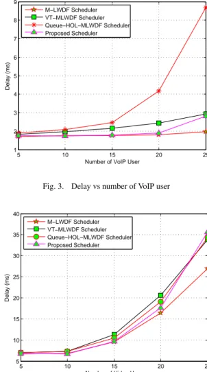
4.2.1 Delay. Figure 3 shows the delay of VoIP flow. It is clear that, the proposed scheduler has the lower delay than the Queue-HOL-MLWDF and the VT-MLWDF schedulers. For the number of VoIP user from 5 to 15, the proposed scheduler has the delay as same as the M-LWDF one. Otherwise, the M-LWDF sched-uler has the lower delay then the proposed schedsched-uler when the number of VoIP user more than 15 UEs.
For the Video flow, such as shown in the Figure 4, the proposed scheduler has the lower delay than the VT-MLWDF and Queue-HOL-MLWDF schedulers when the number of Video user from 5 to 23 UEs. The proposed scheduler has the same delay as the M-LWDF scheduler when the number of Video user from 5 to 15 UEs. However, when the number of Video user more than 15 UEs, the M-LWDF scheduler has the lower delay than the proposed scheduler one.
It can be said that for the number of UE from 5 to 15, the pro-posed scheduler has the same delay when compared to the M-LWDF scheduler and has the lower delay in comparison with the remaining schedulers.
4.2.2 Packet Loss Rate. Figure 5 represents the PLR of VoIP flow. Although the proposed scheduler does not have the good
5 10 15 20 25 1 2 3 4 5 6 7 8 9
Number of VoIP User
Delay (ms)
M−LWDF Scheduler VT−MLWDF Scheduler Queue−HOL−MLWDF Scheduler Proposed Scheduler
Fig. 3. Delay vs number of VoIP user
5 10 15 20 25 5 10 15 20 25 30 35 40
Number of Video User
Delay (ms)
M−LWDF Scheduler VT−MLWDF Scheduler Queue−HOL−MLWDF Scheduler Proposed Scheduler
Fig. 4. Delay vs number of Video user
PLR when compared to the three remaining schedulers, how-ever the proposed scheduler has the lower PLR for the number of VoIP user from 8 to 14 in comparison with the M-LWDF scheduler. Especially, when the number of VoIP user more than or equal to 20, the proposed scheduler has the stable PLR. This is very good when the number of VoIP user more than 25 UEs.
5 10 15 20 25 0 0.05 0.1 0.15 0.2 0.25 0.3 0.35
Number of VoIP User
PLR
M−LWDF Scheduler VT−MLWDF Scheduler Queue−HOL−MLWDF Scheduler Proposed Scheduler
For the Video flow, such as shown in the Figure 6, although the proposed scheduler does not has good PLR when the number of Video user less than 10, when the number of Video user from 10 to 15, the proposed scheduler has the PLR as same as the M-LWDF scheduler one. Specially, the proposed scheduler has the lowest PLR when the number of Video user more than 15 UEs when compared to the remaining schedulers. It can be said that the proposed scheduler is very efficient for the PLR of Video flow when the number of Video user more than 15 UEs.
5 10 15 20 25 0 0.05 0.1 0.15 0.2 0.25 0.3
Number of Video User
PLR
M−LWDF Scheduler VT−MLWDF Scheduler Queue−HOL−MLWDF Scheduler Proposed Scheduler
Fig. 6. Packet loss rate vs number of Video user
4.2.3 Cell throughput. For the VoIP flow, as shown in the Fig-ure 7, the proposed scheduler has the cell throughput as ap-proximate as the remaining schedulers, except the Queue-HOL-MLWDF scheduler has the highest cell throughput when the number of VoIP user from 5 to 8 UEs, the proposed scheduler has the highest cell throughput when the number of VoIP user around 15 UEs. It is clear that the M-LWDF has the lowest cell throughput when the number of VoIP more than 20 UEs.
5 10 15 20 25 1e+04 2e+04 3e+04 4e+04 5e+04 6e+04 7e+04 8e+04 10e+04
Number of VoIP User
Throughput (bps)
M−LWDF Scheduler VT−MLWDF Scheduler Queue−HOL−MLWDF Scheduler Proposed Scheduler
Fig. 7. Throughput vs number of VoIP user
Figure 8 shows the cell throughput of Video flow. The proposed scheduler has the cell throughput as same as the three remaining schedulers when the number of Video user from 5 to 20 UEs. When the number of Video user more than 20, the proposed scheduler has the highest cell throughput in comparison with the M-LWDF, VT-MLWDF and Queue-HOL-MLWDF schedulers.
5 10 15 20 25 4e+05 6e+05 8e+05 10e+05 12e+05 14e+05 16e+05 18e+05 20e+05 22e+05 24e+05
Number of Video User
Throughput (bps)
M−LWDF Scheduler VT−MLWDF Scheduler Queue−HOL−MLWDF Scheduler Proposed Scheduler
Fig. 8. Throughput vs number of Video user
4.2.4 Fairness index. Figure 9 shows the FI of VoIP flow. The proposed scheduler has the FI as same as the M-LWDF and VT-MLWDF schedulers one and higher than Queue-HOL-VT-MLWDF when the number of VoIP from 5 to 15 UEs. Although when the number of VoIP is greater than 17, the proposed scheduler has the lowest FI when compared to the remaining schedulers, but it seems that the proposed scheduler will have the FI strongly increased when the number of VoIP user more than 25 UEs.
5 10 15 20 25
0.45 0.5 0.55 0.6
Number of VoIP User
Fairness Index
M−LWDF Scheduler VT−MLWDF Scheduler Queue−HOL−MLWDF Scheduler Proposed Scheduler
Fig. 9. Fairness Index vs number of VoIP user
For the Video flow, as shown in the Figure 10, the proposed scheduler has the same FI when compared to the remaining schedulers for the number of Video user from 5 to 20. When the number of Video user is more than 20, the proposed sched-uler has the highest FI in comparison with the M-LWDF, VT-MLWDF and Queue-HOL-VT-MLWDF schedulers ones.
4.2.5 Spectral efficiency. Such as shown in the Figure 11, the proposed scheduler has the SE as same as the remaining sched-ulers when the number of user from 5 to 20. When the number of user is more than 20, the proposed scheduler has the highest SE when compared to the M-LWDF, VT-MLWDF and Queue-HOL-MLWDF schedulers ones.
4.2.6 Effects of MQS on the system performance. In order to evaluate the effects of the MQS on the system performance, we simulate the proposed scheduler with the different MQS values and compare in terms of Delay, PLR and Cell throughput. Figure 12 shows the effect of the MQS on the delay of VoIP flow. The
5 10 15 20 25 0.38 0.4 0.42 0.44 0.46 0.48 0.5
Number of Video User
Fairness Index
M−LWDF Scheduler VT−MLWDF Scheduler Queue−HOL−MLWDF Scheduler Proposed Scheduler
Fig. 10. Fairness Index vs number of Video user
5 10 15 20 25 0.1 0.15 0.2 0.25 0.3 0.35 0.4 0.45 0.5 Number of User Spectral Efficiency M−LWDF Scheduler VT−MLWDF Scheduler Queue−HOL−MLWDF Scheduler Proposed Scheduler
Fig. 11. Spectral efficiency vs number of VoIP user
simulation result shows that the lower MQS, the lower delay for VoIP flow. 5 10 15 20 25 1.6 1.8 2 2.2 2.4 2.6 2.8 3
Number of VoIP User
Delay (ms)
MQS = 106 bytes
MQS = 105 bytes MQS = 104 bytes
Fig. 12. The effect of the MQS on the delay of VoIP flow
For the Video flow as shown in Figure 13, the proposed scheduler has the lowest delay for the MQS equal to 104 bytes. For the
MQS equal to 105or 106bytes, the delay of Video flow is nearly
the same. 5 10 15 20 25 5 10 15 20 25 30 35 40
Number of Video User
Delay (ms)
MQS = 106 bytes
MQS = 105 bytes MQS = 104 bytes
Fig. 13. The effect of the MQS on the delay of Video flow
Figure 14 represents the effect of the MQS on PLR of VoIP flow. As the result, there is not any MQS which offers the lowest PLR. However, when the number of VoIP users is more than 20, the proposed scheduler with the MQS = 105 bytes has the stable
PLR. This demonstrates that in this case, the PLR may be also stable when the number of VoIP users more than 25.
5 10 15 20 25 0.05 0.1 0.15 0.2 0.25 0.3 0.35 0.4 0.45 0.5 0.55
Number of VoIP User
PLR
MQS = 106 bytes MQS = 105 bytes MQS = 104 bytes
Fig. 14. The effect of the MQS on the PLR of VoIP flow
For the Video flow, the effect of the MQS on the PLR is repre-sented in Figure 15. The result shows that the proposed scheduler has the same PLR with the MQS equals 105or 106bytes when
the number of Video user is more than or equal to 10. For the MQS is equal to 104bytes, the PLR has the highest PLR which
is about 10 times than the MQS is equal to 105or 106bytes.
Figure 16 shows the effect of the MQS on cell throughput of VoIP flow. In general, the proposed scheduler has the highest cell throughput when the MQS equal to 104bytes and has the
ap-proximate one in comparison with the MQS equal to 105bytes.
In case of the MQS equals 106bytes, the proposed scheduler has
the lowest cell throughput.
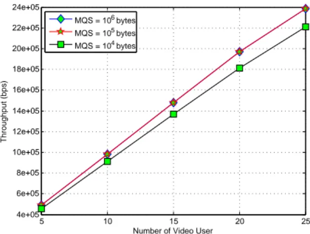
For the Video flow, the effect of the MQS on the cell throughput is represented in Figure 17. The result show that the proposed scheduler has the same cell throughput for the MQS equals 105
or 106 bytes and has the lowest cell throughput for the MQS
5 10 15 20 25 0 1 2 3 4 5 6 7
Number of Video User
PLR
MQS = 106 bytes MQS = 105 bytes
MQS = 104 bytes
Fig. 15. The effect of the MQS on the PLR of Video flow
5 10 15 20 25 1e+04 2e+04 3e+04 4e+04 5e+04 6e+04 7e+04 8e+04 9e+04
Number of VoIP User
Throughput (bps)
MQS = 106 bytes
MQS = 105 bytes
MQS = 104 bytes
Fig. 16. The effect of the MQS on the cell throughput of VoIP flow
5 10 15 20 25 4e+05 6e+05 8e+05 10e+05 12e+05 14e+05 16e+05 18e+05 20e+05 22e+05 24e+05
Number of Video User
Throughput (bps)
MQS = 106 bytes MQS = 105 bytes
MQS = 104 bytes
Fig. 17. The effect of the MQS on the cell throughput of Video flow
5. CONCLUSION
In this paper, we propose a new Channel- and QoS-Aware scheduling scheme for the downlink direction in LTE network. The main idea in the scheduler is the consideration of the MQS factor into the priority metric The metric is the combination of the MQS factor and the metrics of the M-LWDF, VT-MLWDF and Queue-HOL-MLWDF schedulers with essential modifica-tions. The simulation results show that the proposed sched-uler not only meets QoS requirements for real-time services but also outperforms the M-LWDF, VT-MLWDF and Queue-HOL-MLWDF schedulers in terms of PLR, cell throughput, FI and SE, especially for Video flow. The proposed scheduler also improves significantly the delay in comparison with the VT-MLWDF and Queue-HOL-MLWDF schedulers ones for both VoIP and Video flows. It can be said that when considering the MQS as a factor for the metric in the proposed scheduler, the system performance is improved significantly, specially for Video flow. Therefore, it can be concluded that the proposed scheduler is very suitable for real-time services such as VoIP, Video, etc. for the downlink direction in LTE system.
In this study, we have not yet considered the presence of best-effort flow. They might bring new directions to evaluate the pro-posed scheduler in heterogeneous traffic in LTE network.
6. REFERENCES
[1] 3GPP. http://www.3gpp.org.
[2] 3GPP. Requirements for Evolved UTRA (E-UTRA) and Evolved UTRAN (E-UTRAN). TR 25.913, 3rd Generation Partnership Project (3GPP), 12 2009.
[3] 3GPP. Evolved Universal Terrestrial Radio Access (E-UTRA); Physical channels and modulation. TS 36.211, 3rd Generation Partnership Project (3GPP), 03 2010.
[4] Mehdi Alasti, Behnam Neekzad, Jie Hui, and Rath Van-nithamby. Quality of service in wimax and lte net-works [topics in wireless communications]. Communica-tions Magazine, IEEE, 48(5):104–111, 2010.
[5] Salman Ali and Muhammad Zeeshan. A utility based re-source allocation scheme with delay scheduler for lte service-class support. In Wireless Communications and Networking Conference (WCNC), 2012 IEEE, pages 1450– 1455. IEEE, 2012.
[6] Pablo Ameigeiras, Jeroen Wigard, and Preben Mogensen. Performance of the m-lwdf scheduling algorithm for streaming services in hsdpa. In Vehicular technology con-ference, 2004. VTC2004-Fall. 2004 IEEE 60th, volume 2, pages 999–1003. IEEE, 2004.
[7] Francesco Capozzi, Giuseppe Piro, Luigi Alfredo Grieco, Gennaro Boggia, and Pietro Camarda. Downlink packet scheduling in lte cellular networks: Key design issues and a survey. Communications Surveys & Tutorials, IEEE, 15(2):678–700, 2013.
[8] Dakuri Chiranjeevi, V Mahender, B Kiran, and B Raja Kumar. Channel aware scheduling algorithms for 3gpp lte downlink.
[9] Chen-Nee Chuah and Randy H Katz. Characterizing packet audio streams from internet multimedia applications. In Communications, 2002. ICC 2002. IEEE International Conference on, volume 2, pages 1199–1203. IEEE, 2002. [10] Mauricio Iturralde, Tara Ali Yahiya, Anne Wei, and
Andre-Luc Beylot. Performance study of multimedia services us-ing virtual token mechanism for resource allocation in lte networks. In Vehicular Technology Conference (VTC Fall), 2011 IEEE, pages 1–5. IEEE, 2011.
[11] Richard Musabe and Hadi Larijani. Cross-layer schedul-ing and resource allocation for heterogeneous traffic in 3g
lte. Journal of Computer Networks and Communications, 2014, 2014.
[12] Moustafa M Nasralla and Maria G Martini. A downlink scheduling approach for balancing qos in lte wireless net-works. In Personal Indoor and Mobile Radio Communica-tions (PIMRC), 2013 IEEE 24th International Symposium on, pages 1571–1575. IEEE, 2013.
[13] Giuseppe Piro, Luigi Alfredo Grieco, Gennaro Boggia, Francesco Capozzi, and Pietro Camarda. Simulating lte cellular systems: an open-source framework. Vehicular Technology, IEEE Transactions on, 60(2):498–513, 2011. [14] Giuseppe Piro, Luigi Alfredo Grieco, Gennaro Boggia,
Rossella Fortuna, and Pietro Camarda. Two-level down-link scheduling for real-time multimedia services in lte networks. Multimedia, IEEE Transactions on, 13(5):1052– 1065, 2011.
[15] M. Reisslein, L. Karam, and P. Seeling. H. 264/AVC and SVC Video Trace Library: A Quick Reference Guide http://trace. eas. asu. edu. 2009.
[16] Jong-Hun Rhee, Jack M Holtzman, and Dong-Ku Kim. Scheduling of real/non-real time services: adaptive exp/pf algorithm. In Vehicular Technology Conference, 2003. VTC 2003-Spring. The 57th IEEE Semiannual, volume 1, pages 462–466. IEEE, 2003.
[17] Bilal Sadiq, Ritesh Madan, and Ashwin Sampath. Down-link scheduling for multiclass traffic in lte. EURASIP Journal on Wireless Communications and Networking, 2009:14, 2009.
[18] Dardouri Samia and Bouallegue Ridha. A new scheduling algorithm for real-time communication in lte networks. In Advanced Information Networking and Applications Work-shops (WAINA), 2015 IEEE 29th International Conference on, pages 267–271. IEEE, 2015.
[19] Freescale Semiconductor. Long term evolution protocol overview. White Paper, Document No. LTEPTCLOVWWP, Rev 0 Oct, 2008.