HAL Id: hal-01574696
https://hal-mines-albi.archives-ouvertes.fr/hal-01574696
Submitted on 16 Aug 2017
HAL is a multi-disciplinary open access archive for the deposit and dissemination of sci-entific research documents, whether they are pub-lished or not. The documents may come from teaching and research institutions in France or abroad, or from public or private research centers.
L’archive ouverte pluridisciplinaire HAL, est destinée au dépôt et à la diffusion de documents scientifiques de niveau recherche, publiés ou non, émanant des établissements d’enseignement et de recherche français ou étrangers, des laboratoires publics ou privés.
Continuous Process of Extrusion Assisted by
Supercritical CO 2
Margot Chauvet, Fabien Baillon, Martial Sauceau, Jacques Fages
To cite this version:
Margot Chauvet, Fabien Baillon, Martial Sauceau, Jacques Fages. Modelling Nucleation and Cell Size During the Continuous Process of Extrusion Assisted by Supercritical CO 2. 16th European Meeting on Supercritical Fluids (EMSF 2017), ISASF, Apr 2017, Lisbonne, Portugal. �hal-01574696�
Modelling Nucleation and Cell Size During the Continuous
Process of Extrusion Assisted by Supercritical CO
2Margot Chauvet, Fabien Baillon, Martial Sauceau*, Jacques Fages
Université de Toulouse; Ecole des Mines d’Albi; UMR CNRS 5302; Centre RAPSODEE, 81013 Albi, France
* Martial.Sauceau@mines-albi.fr
ABSTRACT
Polymer foaming with the process of extrusion assisted by supercritical CO2 is based on the injection of a supercritical fluid, in our case carbon dioxide, in a polymer, which has been previously melted in the barrel of an extruder. Upon depressurisation that happens in the die, nucleated bubbles will appear and grow. Modelling the nucleation and growth is important to better understand and master the process. A suitable and specific mathematical formulation has been implemented to calculate the number and the size of the pores. A methodology consisting in discretizing the space, to bring back to a succession of batch models was the chosen approach and a functional algorithm has been developed. The model will be applied in the foaming process of poly-lactic acid PLA and will be compared to experimental results.
INTRODUCTION
The process of extrusion assisted by supercritical carbon dioxide (sc-CO2) consists in injecting the pressurised CO2 in the heated barrel of an extruder containing a molten polymer [1]. Physically, different steps occur: sorption and dissolution of gas into molten polymer at elevated pressure before the die, nucleation of bubbles in a supersaturated solution of gas in a molten matrix in the die, growth of bubbles until equilibrium and stabilization of the foam structure by lowering the temperature in and after the die [2].
Shafi et al. [3–6] have developed a model for the nucleation and the growth of the bubbles in batch mode. Only few publications relate to the modelling of extrusion foaming [7]. This is due to the fact that flow induces many changes in the nucleation mechanism and physical properties. In this work, the method of Shimoda et al. [7] will be applied. This approach consists in discretizing the space, to bring back to a succession of batch models.
MATHEMATICAL FORMULATION
Nucleation
The nucleation rate gives information about the number of bubbles nucleated by unit of time and volume. In this work, the choice was to consider a homogeneous nucleation calculated by Equation (1): 𝐽 𝑡 = 𝐶! 𝑡 𝑁! 2𝛾 𝜋𝑚!𝑒𝑥𝑝 16𝜋𝛾! 3𝑘!𝑇 𝑃!"!!#$ 𝑡 − 𝑃!"#$%&' 𝑡 ! Equation (1)
With CA the concentration of the blowing agent, NA the Avogadro number, γ the surface tension, mg the molecular mass of blowing agent, kB the Boltzmann constant, T the polymer temperature, Pbubble the bubble pressure and Ppolymer the polymer pressure.
Bubble growth
Force balance equation at the polymer-gas interface is calculated by Equation (2): 𝑑𝑅 𝑑𝑡 = 𝑃!"!!#$− 𝑃!"#$%&' 𝑅 4𝜂 − 𝛾 2𝜂 Equation (2)
Mass balance over a bubble is calculated by Equation (3): 𝑑 𝑑𝑡 4𝜋 3 𝑃!"!!#$𝑅! ℜ𝑇 = 4𝜋𝑅!𝐷 𝜕𝑐 𝜕𝑟!!! Equation (3)
Gas diffusion in the surrounding polymer is calculated by Equation (4): 𝜕𝑐 𝜕𝑡+ 𝑅𝑅! 𝑟! 𝜕𝑐 𝜕𝑟= 𝐷 𝑟! 𝜕 𝜕𝑟 𝑟! 𝜕𝑐 𝜕𝑟 Equation (4)
With R the bubble radius, η the polymer viscosity, c the concentration of dissolved gas in the polymer, D the diffusivity coefficient and ℜ the universal gas constant.
The initial and boundary limits for the concentration are described in Equation (5): 𝑐 𝑟, 0 = 𝑐!(𝑟)
𝑐 𝑅, 𝑡 = 𝑐! 𝑡 = 𝐾!𝑃!"!!#$(𝑡) 𝑐 ∞, 𝑡 = 𝑐! = 𝐾!𝑃!"!!#$!
Equation (5)
With c0 the initial concentration of dissolved gas in the polymer, KH the solubility coefficient and 𝑃!"!!#$! the initial bubble pressure.
New variables
Representation of the different volumes near the bubble are presented on Figure I. The notion of influence volume (VS) was introduced in Shafi’s studies [3–6]. This influence volume is a region around the bubble where no nucleation of bubble can occur. This is due to the bubble growth: concentration gradients propagate radially in the immediate neighbourhoods of the bubbles. VS is dependent on R (t, t’), bubble radius at time t for a bubble born at time t’, and S (t, t’), radial position where the dissolved gas concentration is equal to the nucleation threshold cs. The nucleation threshold cs is defined as the dissolved gas concentration at which the nucleation is 1 % of the nucleation rate at the initial dissolved gas concentration (classically, cs = 0.95c0). Equation (6) shows the calculation of the influence volume:
𝑉! =
4𝜋
3 (𝑆!− 𝑅!)
Equation (6)
In this approach, the volume of non-influence VL is considered. It is the region where new bubbles can nucleate, it is calculated by Equation (7):
𝑉! 𝑡 = 𝑉! 0 − 𝑉! 𝑡! 𝐽 𝑡! 𝑉
! 𝑡 − 𝑡! 𝑑𝑡! !
!
Equation (7)
In other terms, the non-influence volume will decrease with the nucleation. When VL is equal to zero, the nucleation stops and bubbles can continue to grow by consuming the gas of their influence volume.
Shafi et al. [3–6] have introduced a new variable Vcb. It represents the volume of the melt between the bubble surface and the radial position where the dissolved gas concentration approaches the initial dissolved gas concentration c0.
New variable x is also introduced [3–6]. It represents the melt volume between the bubble surface and radial position r normalized to the volume of concentration boundary region Vcb. The relation between these two new variables is calculated by Equation (8):
𝑥 =4𝜋 3
𝑟!− 𝑅!
𝑉!"
Equation (8)
Figure I. Representation of the different volumes near the bubble. Adapted from [2]
Another normalized variable for the concentration is defined by Equation (9): 𝐶 = 𝑐 − 𝑐!
𝑐!− 𝑐!
Equation (9)
The integral method assumes that the gas concentration profile can be approximated by a polynomial function on Equation (10):
𝐶 = 1 − 1 − 𝑥 !!!!
Equation (10)
Classically, Nd = 3 for the profile concentration.
By modifying Equation (3) and Equation (4) with the new variable defined, the system to be solve takes the following form:
𝑑𝑐! 𝑑𝑡 = 12𝜋𝐷ℜ𝑇𝐾! 𝑅(𝑐!− 𝑐!) 𝑉!" 𝑑𝐶 𝑑𝑥 !!! − 3𝑐! 𝑅 𝑑𝑅 𝑑𝑡 Equation (11)
𝑉!" = 4𝜋 𝑐!𝑅! − 𝑐 !𝑅!! 3𝐾!ℜ𝑇 𝑐!− 𝑐! ∫!! 1 − 𝐶 𝑑𝑥 Equation (12) BATCH APPROACH
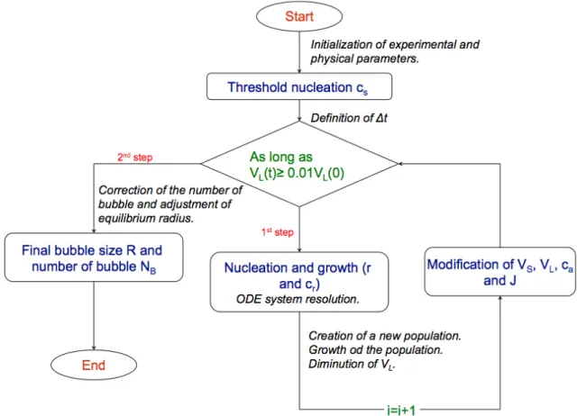
The approach for solving the problem is described on Figure II. During the first step (nucleation and growth), the growth of population takes place during the time interval Δt defined by the user. This step also permits to calculate the influence volume, non-influence volume, gas concentration and nucleation. The bubble populations are calculated as long as non-influence volume VL(t)≥0.01 VL(0). The total growth of a bubble population is not calculated in this step (see Figure III).
During the second step, the final number of bubbles and the size distribution are calculated (see Figure IV) thanks to the influence volume of each bubble.
Figure III. Size of the bubble (during the first step)
Figure IV. Final bubble size (during the second step)
CONTINUOUS APPROACH
Shimoda et al. [7] have shown that to perform the modelling of the nucleation and bubble growth in a flow field, a fluid model should be incorporated. The idea is to integrate the macroscopic flow models to the bubble nucleation and growth model (from Equation 1 to 12). A model describing the flow rate and viscosity as a function of the bubble fraction in the flow has to be chosen.
The final objective of this work is to be able to describe the bubble distribution in the foam obtained with our equipment. Shimoda et al. [7] chose to use a model developed by Baldwin et al. [8]. It consists in modifying the non-Newtonian fluid model of the flow running through a die with a rectangular section. In our case, the extruder is equipped with a cylindrical die. To describe the pressure drop over the length z of the nozzle for a non-Newtonian fluid, the equation is taken from Park et al. [9] (Equation 13):
𝑑𝑃!"#$%&'& 𝑑𝑧 = − 2𝑚𝐿 𝑟! 𝑄 3 +1𝑛 𝜋𝑟!! ! Equation 13
With m and n, rheological data of the polymer, Q the volumetric flow rate and L and r0 the characteristics of the nozzle (length and radius).
Q is also expressed by Equation 14:
𝑄 = 𝑄!+ 𝑄!
Equation 14
The nozzle is divided by N elements of length Δz as seen Figure V. In each section i, the nucleation and growth will be calculated thanks to Equation 1 to 12. Then, with Equation 13 and 14, the new polymer pressure will be calculated and the calculation will be performed in the next element.
Figure V. Schematic diagram of the die
CONCLUSION
Modelling bubble number and size is fundamental for a better understanding and mastering of the continuous polymer foaming by CO2-assisted extrusion process. The present paper has shown that two different stages must be considered: (i) a discontinuous model to represent the nucleation and bubble growth in a batch, (ii) this same model is then implemented to the continuous process by discretizing the flow in the die.
The perspective with this model is to generate theoretical porous structure in order to be able to compare it to experimental foamy samples. The model will be adjusted using fitting parameters of the studied system. The sensitivity of the model to the variation of the operating parameters will also be studied.
REFERENCES
[1] CHAUVET,M.,SAUCEAU,M.,FAGES,J., Extrusion assisted by supercritical CO2: A review on its application to biopolymers, Journal of Supercritical Fluids, Vol. 120, 2017, p. 408.
[2] LEE,S.-T.,PARK,C.B., Foam Extrusion - Principles and Practice, CRC Press, 2000.
[3] SHAFI,M. A,LEE,J.G.,FLUMERFELT,R.W., Prediction of cellular structure in free expansion polymer foam processing, Polymer Engineering and Science, Vol. 36, 1996, p. 1950.
[4] SHAFI,M.A.,FLUMERFELT,R.W., Initial bubble growth in polymer foam processes, Chemical
Engineering Science, Vol. 52, 1997, p. 627.
[5] SHAFI,M.A.,JOSHI,K.,FLUMERFELT,R.W., Bubble size distributions in freely expanded polymer
foams, Chemical Engineering Science, Vol. 52, 1997, p. 635.
[6] JOSHI,K.,LEE,J.G.,SHAFI,M.A.,FLUMERFELT,R.W., Prediction of Cellular Structure in Free Expansion of Viscoelastic Media, Journal of Applied Polymer Science, Vol. 67, 1998, p. 1353.
[7] SHIMODA,M.,TSUJIMURA,I.,TANIGAKI,M.,OHSHIMA,M., Polymeric Foaming Simulation for Extrusion
Processes, Journal of Cellular Plastics, Vol. 37, 2001, p. 517.
[8] BALDWIN,D.F.,PARK,C.B.,SUH,N.P., Cellular and Microcellular Materials, The American Society of
Mechanical Engineers, 1994.
[9] PARK,C.B.,BALDWIN,D.F.,SUH,N.P., Effect of the pressure drop rate on cell nucleation in continuous processing of microcellular polymers, Polymer Engineering Science, Vol. 35, 1995, p. 432.
![Figure I. Representation of the different volumes near the bubble. Adapted from [2]](https://thumb-eu.123doks.com/thumbv2/123doknet/11637406.306730/4.892.233.665.307.713/figure-i-representation-different-volumes-near-bubble-adapted.webp)