Co-registration and complex interpolation Dominique Derauw and Stéphane Roose Centre Spatial de Liège, University of Liège Avenue du Pré Aily, B4031 Angleur, Belgium.
Phone.: .. 32 41 67 66 68 Fax.: .. 32 41 67 56 13 e-mail: [email protected] 1. ABSTRACT
This paper presents a novel and efficient method, based on a modified version of the Chirp-Z transform algorithm, for performing the co-registration of SAR images as required in SAR interferometry. The method allows also complex interpolation of an entire image, by application, at each point, of a bilinear co-ordinate transformation.
2. INTRODUCTION
CSL (Centre Spatial de Liège) has implemented a complete InSAR processor[1] as part of the National Belgian Remote Sensing Program. As part of this program, we developed an adapted filter and a method of phase unwrapping based on residue connection guided by coherency measurements[2]. As an intermediate step we also developed a complex interpolation method for co-registration purposes.
SAR interferometry is a promising and sophisticated technique by which two SAR images of the same scene, acquired from two consecutive passes of the carrying satellite platform, are brought into interference for generating a digital terrain model of the observed surface[3]. Due to the difference in viewing angles and to a non-strict parallelism of the orbits at the times of acquisition, corresponding pixels in the two images are not necessarily associated with the same terrain element, leading to image de-correlation. The pre-requisite for interferometry is therefore that the two images be accurately superimposed to each other, i.e., co-registered[4].
Co-registration consists mathematically in finding a mapping that allows one to relate two complex-valued SAR images, Im1(z1,x1) and Im2(z2,x2), where zi and xi denote, respectively, the slant-range and azimuth co-ordinates in the i-th image. A bilinear transformation is generally adequate, because it takes into account scaling and rotations which are the major effects induced by view angle difference and orbit non-parallelism:
x A x B z C z A x B z C 2 x 1 x 1 x 2 z 1 z 1 z = + + = + + (1)
The six transformation coefficients can be obtained by least-square fitting of complex correlations, i.e., maximisations of local coherence, performed at numerous anchor points in the two images.
Since a SAR image is a digital two-dimensional signal, the bilinear co-ordinate transformation must be applied by interpolation. Additionally, the SAR interferometrical context requires the interpolator to preserve the phase information. A classical implementation is Fourier interpolation[3], in which zeroes are inserted into the spectrum of image 2 leading, after inverse Fourier transform, to an image with smaller sampling interval. Typically, SAR interferometry requires an interpolation rate higher or equal to 8 [3], with a corresponding increase in array sizes by the same factor. Afterwards, a resampling yields the coregistered image.
We propose to use an alternative method based on the Chirp-Z transform (CZT) algorithm[5]. It turns out that the speed and memory requirements of this method are independent of the interpolation rate, and allow interpolation and re-sampling to be performed at the same time. This two-dimensional complex interpolator is applied first along the range dimension, then along the azimuth dimension.
3. THE CZT ALGORITHM AS BASIC OPERATION FOR COMPLEX INTERPOLATION
Let us start from the classical Fourier interpolation of a digital image. In a first step we compute the discrete Fourier transform U(k∆fx) of a given discrete sequence u(n∆x) (our original SAR image). A simple complex interpolation of u(k∆x) is given by the inverse continuous Fourier transform of U(k∆fx).
u x U k fx e2i k fxx k 0 N 1 = = −
∑
∆ π ∆ (2)For xn = n ∆x we obtain the inverse discrete Fourier transform formula.
Consider now the case where the Fourier transform should be evaluated in some discrete points given by the following expression:
xn =n A x B∆ + (3)
Where A represents a linear scale factor and B an offset. After some straightforward calculations[5][6], Eq. (2) with the substitution of x from Eq. (3) can be reorganised as a discrete convolution:
u xn i n g k h n k , n 0,..., N 1 k 0 N 1 = − = − = −
∑
(4) where: g k U k f e h k e i n e x i Ak N B k N i n k N i An N = = = +☺
− − ∆ π π π 2 2 2 2 (5)This expression tells how to calculate the Fourier transform of a given sequence in an arbitrary interval and with an arbitrary sampling rate. The Fourier transform is thus rewritten as a discrete convolution, and consequently the discrete convolution theorem is applied. It requires at least three 2 N points FFT's.
A first great advantage of this interpolation method is the reduced array size, since we can interpolate at a very high interpolation ratio without increasing array sizes. Note, that the interpolated image extent scales down with increasing interpolation ratio. The second advantage is that the interpolation ratio is arbitrary and not necessarily a power of two. The performances are very interesting for two-dimensional sub image interpolation with an interpolation ratio larger than 4. The computation time is in that case always faster than zero-padding techniques. Figure 1 schematises the 1 dimensional interpolation procedure.
FFT g(k) = U(k fx)exp(i (A k²/N + 2B k/N)) g(k) = 0, for k = 0, ..., N-1 for k = N, ..., 2N-1 h(k) = exp(-i Ak²/N) for k = 0, ..., N-1 for k = N, ..., 2N-1 h(k) = exp(-i A(2N - k)²/N) FFT FFT G H IFFT i(n) = exp(i A n² /N) for n = 0, ..., N-1 u(n x) u(x) = i(n) (g h(n)) π π π π ∆ ∆
Figure 1. Organigram of the 1 dimensional interpolation procedure. 4. TWO DIMENSIONAL COMPLEX INTERPOLATION
The previous method is easily generalised to two-dimensional signals, by considering one dimension as a constant while interpolating along the other. As usually done with FFT-algorithms, one considers a separable problem in which the image is processed first row by row, then column by column. In this way, one can rescale and shift images independently in two orthogonal directions. However, the bilinear transform (1) relating the co-ordinate systems of two SAR images is not separable. We adapted our algorithm to a general bilinear transform. It results in a recursive (here in two steps) interpolation.
The first interpolation is done along range, x1 being kept constant. Due to the non-separability we first adapt the coefficients Az, Bz and Cz in such a way that the bilinear transform (1) remains valid. The final image is obtained by interpolating along azimuth. This time, z1 being kept constant.
5. RESULTS
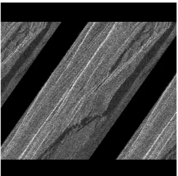
Figure 2 shows a sample image for the test purposes. The objective is to rotate our image by 45 degrees in our frame using our interpolation algorithm. Figure 3 and 4 illustrates the correct algorithm. In a first step (Figure 3) we apply the interpolation in range with corrected coefficients Az, Bz and Cz. These new coefficients take in account the non-separability of the problem. As one remarks the image is not fully rotated by 45 degrees in this first step. However after the second step, interpolating in azimuth, we obtain a complex image rotated by 45 degrees.
Figure 2. Squared modulus of sample image.
Figure 4. Second step of our algorithm, interpolation in azimuth.
Figure 4 demonstrates the power of our algorithm, by illustrating the result of a pure rotation. Another example (Figure 5) combines both scaling (zoom 3 times) and small rotation. The coherent interpolation is recognised by the appearance of speckle in the interpolated points. This is physically correct, since we interpolate a coherent superposition of phase shifted "sinc" functions.
6. CONCLUSIONS
This paper presents the results of a novel recursive technique used for SAR image co-registration. The method is based on the CZT algorithm. It allows arbitrary bilinear interpolation, including scaling, shifting and rotation of two-dimensional images. The method has some advantages in comparison with FFT-techniques with zero-padding, i.e., reduced memory requirements, interpolation and resampling done at the same time. It turns out that for interpolation rates higher than a quarter of a pixel, our algorithm is faster than methods using zero-padding for sub image interpolation.
The most important characteristic is the fact that this method allows to obtain directly, a co-registred complex SAR image, requiring no further processing.
7. ACKNOWLEDGEMENTS
This work was supported by the Belgian Services Fédéraux des Affaires Scientifiques, Techniques et Culturelles (SSTC), under Contract Nr. T3/12/012 of the TELSAT-III National Remote Sensing Program.
8. REFERENCES
1. D. Derauw, Paper 2584-44, Proceedings of SPIE conference 2584 held in Paris, France (1995). 2. D. Derauw, Paper 2584-34, Proceedings of SPIE conference 2584 held in Paris, France (1995).
3. A.K. Gabriel and R.M. Goldstein, "Crossed orbit interferometry: Theory and experimental results from SIR-B.", Int. J.
Remote Sensing, Vol. 9 N° 8, pp857-872, 1988.
4. F.K. Li and R.M. Goldstein, "Studies of multi baseline spaceborne interferometric Synthesis Apperture Radar.", IEEE
Transaction on Geoscience and Remote Sensing, Vol. 28 N°1, pp 88-97, January 1990.
5. L. R. Rabiner and B. Gold, "Theory and applications of digital signal processing", Prentice-Hall, New-Jersey, (1975). 6. S. Roose, B. Brichau & E.W. Stijns, "An efficient interpolation algorithm for Fourier and diffractive optics.", Opt.