HAL Id: tel-02287082
https://tel.archives-ouvertes.fr/tel-02287082
Submitted on 13 Sep 2019HAL is a multi-disciplinary open access archive for the deposit and dissemination of sci-entific research documents, whether they are pub-lished or not. The documents may come from teaching and research institutions in France or abroad, or from public or private research centers.
L’archive ouverte pluridisciplinaire HAL, est destinée au dépôt et à la diffusion de documents scientifiques de niveau recherche, publiés ou non, émanant des établissements d’enseignement et de recherche français ou étrangers, des laboratoires publics ou privés.
Samah Aref Shayya
To cite this version:
Samah Aref Shayya. Towards Rapid and Precise Parallel Kinematic Machines. Automatic. Université Montpellier, 2015. English. �NNT : 2015MONTS257�. �tel-02287082�
Délivré par UNIVERSITE DE MONTPELLIER
Préparée au sein de l’école doctorale Information,
Structures et Systèmes
Et de l’unité de recherche Laboratoire d’Informatique de
Robotique et de Microélectronique de Montpellier
Spécialité : Génie Informatique, Automatique et
Traitement du Signal
Présentée par Samah Aref SHAYYA
Soutenue le 19/02/2015 devant le jury composé de
M. Andreas MÜLLER, Professeur, Johannes Kepler Universität, Linz, Autriche
Rapporteur (Président du Jury) M. Stéphane CARO, Chargé de recherche CNRS,
IRCCyN, Nantes, France
Rapporteur M. Pascal RAY, Professeur, Institut Mines-Télécom,
Saint Etienne, France
Examinateur M. Franck JOURDAN, Professeur UM, LMGC,
Montpellier, France
Examinateur M. Cédric BARADAT, Dr., Directeur technologique,
Tecnalia France, Montpellier, France
Examinateur M. Sébastien KRUT, Chargé de recherche CNRS,
LIRMM, Montpellier, France
Co-Encadrant de Thèse M. Olivier COMPANY, Maître de Conférences UM,
LIRMM, Montpellier, France
Co-Encadrant de Thèse M. François PIERROT, Directeur de recherche
CNRS, LIRMM, Montpellier, France
Directeur de Thèse
Vers des Robots et Machines Parallèles
Rapides et Précis
(Towards Rapid and Precise Parallel
Kinematic Machines)
This doctoral thesis would not have been possible without the support, provision, and wise guidance of my supervisors: Dr. Sébastien KRUT, Dr. Olivier COMPANY, Dr. Cédric BARADAT (industrial supervisor), and Dr. François PIERROT. Their plentiful knowledge and experiences have been very essential in paving my research path and sculpting my research skills. They never hesitated to inspire me with their brilliant ideas and in‐depth scrutiny, while keeping the necessary balance between their recommendations and my independent ideas. For them, I would like to express my sincere gratitude and acknowledgement for all what they have done! Thank you all!
I further thank Dr. KRUT for his tremendous efforts and close contact regarding my work and advancement. Perhaps, he worked as much as I have or even more in this project, especially in the scope of control implementation. His kind help has been indispensable for the success of this research and for which I owe him many thanks!
I would like also to thank the engineering team at Symétrie, the company that executed the prototype, for their efforts and creativity. Their work made the project a reality. Thank you! Furthermore, I would like to thank all the jury members, Pr. Andreas MÜLLER, Dr. (HDR) Stephane CARO, Pr. Pascal RAY, and Pr. Franck JOURDAN, for accepting the evaluation and examination of my thesis, and for their rigorous scrutiny and comments. Having them assess my work is a great honor. For them, I express my genuine respect, gratefulness, and appreciation!
In addition, I would like to thank Tecnalia France for funding my thesis and providing me with all the needed support. I address many thanks to Dr. Valerie AUFFRAY and Dr. Frederick VAN MEER, the current and former directors of Tecnalia France, for welcoming me in the company. Additionally, I owe many thanks for my colleagues at Tecnalia: Dr. Micaël MICHELIN, Dr. Lotfi CHIKH, Dr. Jean‐Baptiste IZARD, Dr. Hai YANG, and Dr. Vincent NABAT, for their enriching discussions and encouragement. Thank you Micaël and Hai for the precious help in the control aspects. I learned a lot from you! Thank you Lotfi for all the experience you have shared with me, especially regarding calibration. Thanks to Ms. Justin ANCEL and Ms. Emmanuelle BOUGEROL, the former and current executive assistants at Tecnalia France, for all their help in the administrative issues.
Special thanks go to Dr. Rany RIZK for recommending me as candidate for this doctoral thesis, and for the trust he has invested in me. Other special thanks I would like to address to Pr. Etienne DOMRE, Dr. Ahmed CHEMORI, and Dr. Marc GOUTTEFARDE, for the enlightening discussions and heartfelt encouragement at many occasions.
At LIRMM, many people have kindly aided me in different aspects and at various occasions, namely: Pr. Pascal NOUET (the responsible of specialty and representative of the Ecole Doctorale), Mr. Michel BENOIT (for his precious help in the experimentation with the LIRMM rapid prototypes), Mr. Olivier TEMPIER (for his technical support), Mr. Pierre‐Elie HERVE, Mrs. Cécile LUKASIK, Mr. Nicolas SERRURIER (for all his help in administrative issues at LIRMM), Ms.
Elisabeth GREVERIE, and Mrs. Genevieve CARRIERE. For all of them, I express my sincere gratitude and appreciation. Thank you all!
During these three years, I have shared many enjoyable discussions with many colleagues, some of which have already graduated and others who are still working on their dissertations. I would like to thank them for all these good memories. In names, I mention: Alain HASSOUN, Divine MAALOUF, Abdulrahman ALBAKRI, Dinh Quan NGUYEN, Andrea COLLO, Florent VEYE, Fabien DESPINOY, Mariam ABDALLAH, Rida KHEIRALLAH, Mohamad NAJEM, Julien PRADES, Moussab BENNEHAR, Mohamed BOUSHAKI, Jing GUO, Ederson DORILEO, Gamal ELGHAZALY, Ayad AL‐DUJAILI, and Irina GAVRILOVICH.
Finally, I owe my success to my ever‐supporting parents and brothers. Whatever I say and whatever I do, I cannot fulfill the least of their rights, especially my mother (Mona) and father (Aref). A thank you is nothing in front of your sacrifices, perseverance, and unlimited giving. You have been and will always be my source of inspiration and my motive to do the best. You are the main contributors for my success and if this presented work deserves any sort of appreciation, you are the ones who should be praised, for you being the source. For you my dear parents and brothers (Farid, Wissam, and Samer), I give my deepest thanks and appreciation, and for you I dedicate this dissertation!
At last, thanks for God, the creator of everything and my source of strength, hope, and enthusiasm. Thank you God for all the blessings you have endowed me!
Parallel manipulators (PMs) have been there for more than half a century and they have been subject of intensive research. In comparison with their serial counterparts, PMs consist of several kinematic chains that connect the fixed base to the moving platform. The interest in such architectures is due to the several advantages they offer, among which we mention: high rigidity and payload‐to‐weight ratio, elevated dynamical capabilities due to reduced moving masses (especially when the actuators are at or near the base), better precision, higher proper frequencies, etc. Nevertheless, despite of the aforementioned merits, their exploitation as machine tools is still timid and limited, in which they most often do not exceed the research and prototyping stages at university laboratories and machine tool manufacturers. The main drawbacks that hinder the widespread of parallel kinematic machines (PKMs) are the following: limited operational workspace and tilting capacity, presence of singular configurations, design complexities, calibration difficulties, collision‐related problems, sophistication of control (especially in the case of actuation redundancy), etc. Besides, though PMs have met a great success in pick‐and‐place applications, thanks to their rapidity (acceleration capacity), still their precision is less than what has been initially anticipated. On the other hand, extremely precise PMs exist, but unfortunately with poor dynamic performance. Starting from the aforementioned problematics, the current thesis focuses on obtaining PKMs with a good compromise between rapidity and precision. We begin by providing a survey of the available literature regarding PKMs and the major advancements in this field, while emphasizing the shortcomings on the level of design as well as performance. Moreover, an overview on the state of the art regarding performance evaluation is presented, and the inadequacies of classical measures, when dealing with redundancy and heterogeneity predicaments, are highlighted. In fact, if finding the proper architectures is one of the prominent issues hindering PKMs’ widespread, the performance evaluation and the criteria upon which these PKMs are dimensionally synthesized are of an equal importance. Therefore, novel performance indices are proposed to assess precision, kinetostatic, and dynamic capabilities of general manipulators, while overcoming the aforementioned dilemmas. Subsequently, several novel architectures with 3T‐2R and 3T‐1R degrees of freedom (T and R signify translational and rotational degrees of freedom), namely MachLin5, ARROW V1, and ARROW V2 with its mutated versions ARROW V2 M1/M2, are presented. Furthermore, the dimensional synthesis of the executed PKM, namely ARROW V2 M2, is discussed with its preliminary performances and possible future enhancements, particularly regarding precision amelioration.
Key words:
Parallel kinematic machines (PKMs), rapidity, precision, large operational workspace, large tilting capacity, actuation redundancy, kinematic redundancy, performance indices, 3T‐2R and 3T‐1R PKMs, MachLin5 PKM, ARROW V1 PKM, ARROW V2 PKM, ARROW V2 M1/M2 PKMs
Les machines parallèles (MPs) existent depuis plus d'un demi‐siècle et ils ont fait l'objet d’études intensives. Par opposition avec leurs homologues de structure série, ces mécanismes sont constitués de plusieurs chaînes cinématiques qui relient la base fixe à la plateforme mobile. L'intérêt de ces architectures s’explique par les nombreux avantages qu'elles offrent, parmi lesquels: une rigidité élevée, un rapport important charge/poids global, des capacités dynamiques élevées en raison des masses en mouvement réduites (en particulier lorsque les actionneurs sont sur ou près de la base), une meilleure précision, des fréquences propres plus élevées, etc. Néanmoins, leur exploitation comme machines‐outils reste timide et limitée, et le plus souvent elles ne dépassent pas le stade d’étude et de prototype de laboratoires universitaires ou de fabricants de machines‐outils. Les principaux inconvénients qui entravent la généralisation des MPs dans l’industrie sont les suivants: un espace de travail limité, des débattements angulaires réduits, la présence de configurations singulières, la complexité de conception, les difficultés d'étalonnage, les problèmes causés par les collisions, la complexité du contrôle/commande (en particulier dans le cas de redondance à actionnement), etc. De plus, si les MPs ont rencontré un grand succès dans les applications de pick‐and‐place grâce à leur rapidité (capacité d’accélération), leur précision reste inférieure à ce qui a été prévu initialement. Par ailleurs, on trouve également des MPs de très précision, mais malheureusement avec de faibles performances dynamiques. En partant du constat précédant, cette thèse se concentre sur l'obtention de MPs avec un bon compromis entre rapidité et précision. Nous commençons par donner un aperçu de la bibliographie disponible concernant MPs et les avancées majeures dans ce domaine, tout en soulignant les limites de performance des MPs, ainsi que les limites des outils de conception classique. En outre, nous insistons sur les outils d’évaluation des performances, et montrons leurs limites dès qu’il s’agit de traiter le cas de la redondance ou l'hétérogénéité des degrés de liberté (ddl). En effet, si la synthèse architecturale est un point dur de la conception de MPs, la synthèse dimensionnelle reposant sur des indices de performances réellement significatifs l’est également. Par conséquent, de nouveaux indices de performance sont proposés pour évaluer la précision, les capacités cinétostatiques et dynamiques des manipulateurs de manière générale qui apportent des solutions aux difficultés évoquées ci‐dessus. Par la suite, plusieurs nouvelles architectures 3T‐ 2R et 3T‐1R (T: signifie ddl en translation et R signifie un ddl de rotation) sont présentées, à savoir MachLin5, ARROW V1, et ARROW V2 et ses versions dérivées ARROW V2 M1 et M2. En outre, la synthèse dimensionnelle d’ARROW V2 M2 est réalisée, et les performances de la machine sont évaluées. Finalement, des améliorations futures concernant la précision sont proposées au regard de premiers résultats obtenus sur le prototype.
Mots clés:
Machines parallèles (MPs), rapidité, précision, grand espace de travail opérationnel, grande capacité d'inclinaison, redondance à actionnement, redondance cinématique, indices de performance, 3T‐2R et 3T‐1R MPs, MachLin5 MP, ARROW V1 MP, ARROW V2 MP, ARROW V2 M1/M2 MPs
General Introduction ... xvi Context ... xvi Motivations ... xvii Contributions ... xviii Notations ... xix Chapter 1: State of the Art... 1 1.1‐ Generalities and Definitions ... 2 1.1.1‐ A Brief History on the First Parallel Robots and Parallel Kinematic Machine Tools ... 2 1.1.2‐ Serial Robots ... 4 1.1.3‐ Parallel Robots ... 5 1.2‐ State of the Art of PMs: Between Theoretical Synthesis and Industrial Implementation . 10 1.2.1‐ Type Synthesis of Parallel Mechanisms ... 10 1.2.2‐ Some Parallel Robots and Parallel Kinematic Machine Tools ... 17 1.3‐ Precision‐Related Performances of Some Prototypes ... 37 1.4‐ Performance Criteria and Parallel Kinematic Machine Tools ... 39 1.5‐ Thesis Outline ... 44 Chapter 2: Performance Evaluation of General Manipulators ... 46 2.1‐ Introduction ... 47 2.1.1‐ Kinematic Redundancy (KR) ... 47 2.1.2‐ Actuation Redundancy (AR) ... 48 2.1.3‐ Mixed‐Redundancy Manipulators (MRMs) ... 49 2.2‐ General Rigid Manipulators ... 50 2.2.1‐ Generalities on the Kinetostatics of Redundant and Non‐Redundant Manipulators . 50 2.2.2‐ Precision‐Related Performance Measures ... 52 2.2.3‐ Kinetostatic Performance Evaluation ... 58 2.2.4‐ Dynamic Performance Evaluation: A Novel Approach Based on Multi‐Assessment of Isotropic Dynamic Capabilities ... 69 2.3‐ Cable‐Driven Parallel Robots (CDPRs) ... 74
2.3.2‐ Generalities on the Kinetostatics of CDPRs ... 75
2.3.3‐ Kinetostatic Performance Evaluation of CDPRs: An Extension of the Approach Applied on Rigid Manipulators ... 77 2.3.4‐ Dynamic Performance Analysis of CDPRs: An Extension of the Approach Applied on Rigid Manipulators ... 83 2.5‐ General Guidelines and Recommendations for the Design Optimization of Machine Tools ... 89 2.6‐ Conclusion ... 90 Chapter 3: The Novel Synthesized Architectures and ARROW PKM ... 91 3.1‐ Introduction ... 92 3.2‐ MachLin5: A 5‐DoF (3T‐2R) Parallel Mechanism with Articulated Platform ... 93 3.2.1‐ Description ... 93 3.2.2‐ Inverse Geometric Model (IGM) ... 96 3.2.3‐ Direct Geometric Model (DGM) ... 97 3.2.4‐ Kinematic Model ... 98 3.2.5‐ Singularity Analysis ... 100 3.2.6‐ Workspace and Kinetostatic Performance ... 102 3.2.7‐ Synopsis ... 105 3.3‐ ARROW V1: A Redundantly Actuated Four‐DoF (3T‐1R) Parallel Manipulator ... 106 3.3.1‐ Description ... 106 3.3.2‐ Inverse Geometric Model (IGM) ... 108 3.3.3‐ Direct Geometric Model (DGM) ... 108 3.3.4‐ Kinematic Model ... 110 3.3.5‐ Singularity Analysis ... 111 3.3.6‐ Simplified Dynamic Model (SDM) ... 113 3.3.7‐ Dimensional Synthesis Based on Dual Criteria: Precision and Dynamics ... 115 3.3.8‐ Synopsis ... 123 3.4‐ ARROW V2: From Theoretical Concept to Prototype Execution ... 124 3.4.1‐ ARROW V2: An Enhanced Version of ARROW V1 ... 124 3.4.2‐ Manufacturability Study of ARROW V2 and Its Mutated Versions ... 131 3.4.3‐ ARROW V2 M2: The Implemented PKM ... 133 3.5‐ Conclusion ... 154
Compensation ... 155 4.1‐ Introduction ... 156 4.2‐ ARROW V2 M2 Prototype: The Basic Control Strategy and Treatment of Redundancy .. 156 4.3‐ Preliminary Precision Evaluation of ARROW V2 M2 PKM ... 158 4.4‐ Geometric Calibration and Methodology of Error Compensation ... 161 4.4.1‐ Geometric Sensitivity of ARROW V2 M2 ... 162 4.4.2‐ Compensation of Geometric Errors of ARROW PKM ... 169 4.4.3‐ General Remarks on Geometric Calibration ... 172 4.5‐ Compensation of Elastic Deformation ... 172 4.6‐ Conclusion ... 174 General Conclusions and Perspectives ... 175 Possible Advancements Regarding the Suggested Performance Measures ... 175 Possible Improvements Regarding ARROW Machine ... 176 Bibliography ... 178 Appendices ... 193 Appendix A: Precision‐Related Performances of Some Rapid Industrial Robots and Prototypes at LIRMM ... 193 A.1‐ Generalities and Definitions ... 193 A.2‐ Briefing on the Procedure and Main Results ... 196 Appendix B: Derivation of Lower Bounds for the Dynamic Specific Isotropic Values in the Case of Rigid Manipulators ... 207 B.1‐ The Derivation Procedure ... 207 B.2‐ Optimization Using Lagrange Multipliers ... 217 B.3‐Case Study: DUAL V ... 220 Appendix C: The Establishment of the Operational Wrench Zonotope of Cable‐Driven Parallel Robots (CDPRS) in Statics ... 224 Appendix D: Dynamic Performance Evaluation of CDPRs ... 227 D.1‐Formulation of the Dynamic Model for CDPRs ... 227 D.2‐ Case Study: A Fully‐Constrained CDPR ... 228 Appendix E: Photos of ARROW Machine ... 232 Publications ... 234
Fig. 1‐1: Original Gough platform and shortly before its transfer into the British National Museum of Science and Industry in 2000 (Dunlop Tyres). ... 2 Fig. 1‐2: FlexPicker (ABB Robotics) industrial robot: photo and graph diagram. ... 3 Fig. 1‐3: Variax parallel kinematics machine tool (Giddings & Lewis). ... 3 Fig. 1‐4: Robot IRB 7600‐150 (ABB Robotics): photo and graph diagram. ... 5 Fig. 1‐5: Hexamove system (OHE Hagenbuch AG): photo and graph diagram. ... 5
Fig. 1‐6: Singularities: series singularity (or RI singularity) (left), parallel singularity (or RO singularity) (middle), and internal singularity (or RPM singularity) (right). ... 10
Fig. 1‐7: Two fully isotopic translational PMs: the left is one of the T3 family (it is more precisely maximally regular), whereas on the right is a type II of T4 family (CARRICATO & PARENTI‐CASTELLI, 2002). ... 12
Fig. 1‐8: The isotropic 3‐CRR translational PM (KONG & GOSSELIN, 2002). ... 12
Fig. 1‐9: Schematics of the Pantopteron (fully isotropic translational PM) (BRIOT & BONEV, 2009). ... 13
Fig. 1‐10: Pantopteron with four‐dof (3T‐1R) uncoupled PM (BRIOT & BONEV, 2009). ... 13
Fig. 1‐11: Models of two fully isotropic mechanisms for Schoenflies motion (CARRICATO, 2005). ... 14
Fig. 1‐12: Example of basic kinematics structure of PM with decoupled Schönflies motions: Isoglide4‐T3R1‐A5 schematic and its constructed prototype at the French Institute of Advanced Mechanics (GOGU, 2007). ... 14
Fig. 1‐13: Uncoupled (PMs) with Schönflies motion: Isoglide4‐T3R1‐B5 (GOGU, 2007). Note that this (PM) is similar to Isoglide4‐T3R1‐A5 in Fig. 1‐12, except that 2C ≡1D. ... 15
Fig. 1‐14: Example of kinematic structure of fully isotropic PM with Schönflies motions: Isoglide4‐T3R1‐C5‐2 (GOGU, 2007). ... 15
Fig. 1‐15: From left to right and top to bottom: Isoglide5‐T3R2‐A1 (5‐PPPRR‐type) (decoupled), Isoglide5‐T3R2‐B1 (uncoupled), Isoglide5‐T3R2‐C1 (maximally regular), and Isoglide5‐T3R2‐C3 (maximally regular) (GOGU, 2009). ... 16
Fig. 1‐16: HEXA Robot: prototype and graph diagram. ... 18
Fig. 1‐17: HexaM Machine Tool (Toyoda): CAD drawing, graph diagram and photo. ... 18
Fig. 1‐20: Lambda Kinematics machine tool: CAD drawing and graph diagram. ... 20 Fig. 1‐21: Fanuc M‐3iA robot (http://www.fanucrobotics.fr/fr/countries/frfr/news/m3ia). . 20 Fig. 1‐22: Hexapteron: schematic drawing, the under‐construction mechanical design, and the close‐up view of the mobile platform at an extreme orientation (SEWARD & BONEV, 2014). 21 Fig. 1‐23: Seyanka (Tekniker): photo and graph diagram. ... 22 Fig. 1‐24: P 800 (Metrom): photo and graph diagram. ... 22 Fig. 1‐25: Tricept 845 (Neos Robotics AB): photo and graph diagram. ... 23 Fig. 1‐26: Exechon (Exechon AB): photo and graph diagram. ... 23 Fig. 1‐27: Sprint Z3 (DS Technology): photo of the wrist and graph diagram. ... 24 Fig. 1‐28: Hermes (Fatronik, now Tecnalia): photo and graph diagram. ... 24 Fig. 1‐29: Dumbo (IFW): photo and graph diagram. ... 25
Fig. 1‐30: Orthoglide five‐axis version (IRCCyN): schematic, graph diagram, simplified CAD drawing, and prototype photo. ... 25 Fig. 1‐31: VERNE machine (Fatronik, now Tecnalia): a photo and a schematic depicting the top view of the parallel module along its direction (from (KANAAN, et al., 2009)). ... 26 Fig. 1‐32: Hita‐STT (parallel module): CAD drawing and graph diagram. ... 27 Fig. 1‐33: A five‐dof (3T‐2R) PKM: global schematic, fifth limb illustration, and machine photo (GAO, et al., 2006). ... 27 Fig. 1‐34: The five‐dof Gantry‐Tau PKM (ABB Robotics): schematic and photo (from (TYAPIN & HOVLAND, 2013)). ... 28 Fig. 1‐35: ROBOTEX machine (LIRMM): CAD drawing and photo... 28 Fig. 1‐36: Eureka (KRUT, et al., 2003): CAD design and graph diagram. ... 29 Fig. 1‐37: Five‐dof (3T‐2R) manipulator (ANCUTA, 2008): schematic and graph diagram. ... 29 Fig. 1‐38: Manta (ROLLAND, 1999): schematic and graph diagram. ... 30 Fig. 1‐39: Kanuk (ROLLAND, 1999): schematic and graph diagram. ... 30 Fig. 1‐40: H4 robot (COMPANY, 2000): photo and graph diagram. ... 32
Fig. 1‐41: H4 articulated platform: basic platform (left) and modified platform including amplification gear assembly (right) (image from (KRUT, 2003)). ... 32
Fig. 1‐42: H4 modified version (KRUT, 2003): photo and graph diagram. ... 32
Fig. 1‐43: I4L prototype (KRUT, 2003): photo, platform close‐up view, CAD drawing, and graph diagram. ... 33
and cable‐pulley amplification mechanisms. ... 33 Fig. 1‐45: Industrialized version of Par4 (Adept Quattro). ... 34 Fig. 1‐46: Héli4 (NABAT, 2007): CAD drawing, graph diagram, prototype photo, and close‐up view of the platform. ... 34 Fig. 1‐47: Veloce (Penta Robotics): photo and platforms (on the left corresponds to the case of three dofs (3T), and on the right corresponds to the case of four dofs (3T‐1R)). ... 35 Fig. 1‐48: λ‐Quadriglide‐V1 (ANCUTA, 2008): schematic, graph diagram and prototype photo. ... 35
Fig. 1‐49: The SMG of McGill University (ANGELES, et al., 2006): CAD drawing and clarifying schematic. ... 36
Fig. 1‐50: Four‐dof (3T‐1R) parallel manipulator (KIM, et al., 2009): photo of exemplary device, clarifying schematic, and graph diagram. ... 37
Fig. 2‐1: Speed‐R‐Man (from http://www.onera.fr/fr/dcsd/robots‐paralleles?page=2). ... 48
Fig. 2‐2: A simple example on mixed redundant manipulators: two series prismatic joints in parallel with another prismatic joint (one dof and three actuators). ... 49
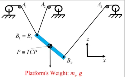
Fig. 2‐3: DUAL V: prototype, CAD drawing and simplified schematic diagram showing the principal geometric parameters. ... 57 Fig. 2‐4: DUAL V: translational and orientation precision amplification factors TPAF (left) and OPAF (right), for the case of zero rotation. ... 57 Fig. 2‐5: Geometrical interpretation of specific isotropic values in the case of two‐dof (1T‐1R) robot. ... 65 Fig. 2‐6: Geometrical interpretation of specific isotropic values in the case of three‐dof (2T‐1R) robot. ... 65 Fig. 2‐7: DUAL V kinetostatic performance evaluation: the specific isotropic values (a) and the satisfactory regions (b). ... 68 Fig. 2‐8: A partially constrained CDPR with three dofs (2T‐1R) in the vertical plane: x, z and Θ (rotation about y‐axis) motion. ... 76
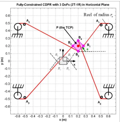
Fig. 2‐9: A fully constrained CDPR with horizontal planar motion (2T‐1R) (grey configuration corresponds to zero rotation). ... 81
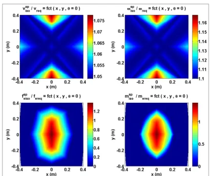
Fig. 2‐10: Ratios of specific isotropic values to corresponding requirements for the CDPR in Fig. 2‐9. ... 82
Fig. 2‐11: Satisfactory regions in terms of kinetostatic performances based on specific isotropic values for the CDPR in Fig. 2‐9. ... 83
Fig. 3‐2: MachLin5: the articulated platform. ... 94
Fig. 3‐3: MachLin5: graph diagram. ... 94
Fig. 3‐4: MachLin5 ‐ FVIh performance: case of zero rotation (left) and case of rotation (i.e. 90 z and y 45 ) (right). ... 103
Fig. 3‐5: MachLin5 ‐ p iso v performance: case of zero rotation (left) and full‐range rotation (right). ... 104
Fig. 3‐6: MachLin5 ‐ p iso f performance: case of zero rotation (left) and full‐range rotation (right). ... 104
Fig. 3‐7: ARROW V1 PKM: CAD drawing and graph diagram. ... 107
Fig. 3‐8: Frontal view of ARROW V1 PKM and close‐up side view of its platform. ... 107
Fig. 3‐9: Pareto diagram of ARROW V1 and the chosen geometric parameters... 118
Fig. 3‐10: TPAF of ARROW V1: case of z (left) and case of 0 z 45 (right). ... 120
Fig. 3‐11: ILA of ARROW V1: case of z (left) and case of 0 z 45 (right). ... 120
Fig. 3‐12: p iso v of ARROW V1: case of z (left) and case of 0 z 45 (right). ... 121
Fig. 3‐13: p iso f of ARROW V1: case of z (left) and case of 0 z 45 (right). ... 121
Fig. 3‐14: PLA of ARROW V1: case of z (left) and case of 0 z 45 (right). ... 121
Fig. 3‐15: Spatial workspace of ARROW VI in the case z and for stroke lengths: 0 1.49 m s SL (actuators 1, 2, 5 and 6) and SLp 1.53 m (actuators 3 and 4). ... 122
Fig. 3‐16: Spatial workspace of ARROW VI in the case z 45 and for stroke lengths: 1.49 m s SL (actuators 1, 2, 5 and 6) and SLp 1.53 m (actuators 3 and 4) ... 123 Fig. 3‐17: ARROW V2: CAD views and notations. ... 125 Fig. 3‐18: The platform of ARROW V2 and its corresponding notations. ... 126 Fig. 3‐19: The five‐dof (3T‐2R) machine tool: ARROW V2 with turntable. ... 126 Fig. 3‐20: Graph diagram of ARROW V2 M1/M2, the mutated versions of ARROW V2. ... 132
Fig. 3‐21: Visualization of the offsets between the revolute joints in ARROW V2 M1/M2 versions (top view): ARROW V2 M1 corresponds to having rp and 0 r , whereas ARROW 0 V2 M2 corresponds to the situation where rp and 0 r . ... 1320 Fig. 3‐22: ARROW V2 M2: 3D CAD view. ... 132
Fig. 3‐25: The complex chains (III) and (IV) with notations. ... 139
Fig. 3‐26: Singularity analysis: case e mTx i0 0. ... 143
Fig. 3‐27: Singularity analysis: case ezT
Li0µi0
0 ... 143Fig. 3‐28: Pareto diagram of ARROW V2 M2 with the two potential candidates encircled in red. ... 149
Fig. 3‐29: ARROW V2 M2 PKM ‐ ILA capacity: case z (left) and case 0 z
45 ; 45
(right). ... 150Fig. 3‐30: ARROW V2 M2 ‐ TPAF performance: case z (left) and case 0 z
45 ; 45
(right). ... 151Fig. 3‐31: ARROW V2 M2 PKM ‐ p iso v capacity: case z (left) and case 0 z
45 ; 45
(right). ... 151Fig. 3‐32: ARROW V2 M2 PKM ‐ p iso f capacity: case z (left) and case 0 z
45 ; 45
(right). ... 152Fig. 3‐33: ARROW V2 M2 PKM ‐ PLA capacity: case z (left) and case 0 z
45 ; 45
(right). ... 152 Fig. 3‐34: ARROW V2 M2: illustrations of the spatial workspaces in the case of z (top) 0 and z (bottom). ... 153
45 ; 45
Fig. 3‐35: ARROW V2 M2 PKM with turntable (rendered CAD drawing). ... 153 Fig. 4‐1: ARROW V2 M2 PKM prototype: basic control model. ... 157 Fig. 4‐2: The tested trajectory profile... 159 Fig. 4‐3: Actuated‐joint tracking errors for the trajectory profile in Fig. 4‐2. ... 160 Fig. 4‐4: Estimated tracking errors in the operational space. ... 160 Fig. 4‐5: ARROW PKM geometric calibration: the main relations. ... 161 Fig. 4‐6: Calibration parameters of the simple PSRR chain. ... 163 Fig. 4‐7: Calibration parameters of the complex P(SRR)2 chain. ... 163 Fig. 4‐8: Mean absolute geometric sensitivity of ARROW V2 M2 prototype... 166Fig. 4‐9: Estimated standard deviation of absolute geometric sensitivity of ARROW V2 M2 prototype. ... 167
Fig. 4‐10: Schematic of the turntable of ARROW machine with notations. ... 169
Fig. 4‐11: Illustration of the impact of the rotation T rot x t PM e e of the turntable. ... 170
Fig. Ap‐2: Illustration of multi‐directional variation of accuracy (VAPpin the figure) [ISO 9283; 1998 (F)]. ... 195
Fig. Ap‐3: Illustration of trajectory positional accuracy (ATp) and trajectory positional
repeatability (RTp) [ISO 9283; 1998 (F)]. ... 196
Fig. Ap‐4: Metris K600 CMM measuring device... 197
Fig. Ap‐5: Experimental setup: an illustrative schematic (left) and a close‐up view on the LEDs assembly on the platform (right). ... 197
Fig. Ap‐6: The largest inscribed cube or rectangular parallelepiped within the accessible workspace, the diagonal plane, and the test points (P P1... 5). ... 198 Fig. Ap‐7: Illustration of the possible cycle schemes. ... 198
Fig. Ap‐8: Multi‐directional variation of accuracy: poses (P1, P2, and P4) and the three directions of approach for the pose Pi (A Pi i, B Pi i, and C Pi i, with i1, 2, 4). ... 199
Fig. Ap‐9: Adept Quattro platforms: articulated (four dofs 3T‐1R on the left) and rigid (three dofs 3T on the right) (http://www.adept.com/products/robots/parallel/quattro‐ s650h/downloads). ... 200
Fig. Ap‐10: Par2 (on the left) and DUAL V (on the right) (LIRMM). ... 204
Fig. Ap‐11: DUAL V: schematic showing principal geometric parameters and center‐of‐mass positions of the different parts. ... 220
Fig. Ap‐12: DUAL V dynamic analysis: ratios of specific isotropic values’ lower bounds relative to their corresponding requirements in the case of zero rotation. ... 222
Fig. Ap‐13: DUAL V: the regions with specific isotropic values’ lower bounds greater or equal to their corresponding requirements in the case of zero rotation. ... 222
Fig. Ap‐14: Ratios of specific isotropic values’ lower bounds relative to corresponding requirements for the CDPR presented in Fig. 2‐9. ... 230
Fig. Ap‐15: Satisfactory regions based on lower bounds of specific isotropic dynamic values for the CDPR presented in Fig. 2‐9. ... 230
Fig. Ap‐16: ARROW V2 M2 prototype. ... 232
Fig. Ap‐17: ARROW V2 M2 prototype: close‐up image of the platform. ... 232
Fig. Ap‐18: ARROW machine CAD drawing: close view on the turntable showing the springs used to counteract the gravity effect. ... 233
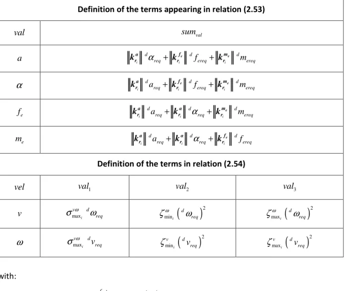
Table 2‐1: DUAL V actuators’ characteristics and the desired kinetostatic requirements.* .... 67 Table 2‐2: The significance of the general terms used in relations (2.53) and (2.54). ... 73 Table 2‐3: The speed and static load requirements for the CDPR in Fig. 2‐9* ... 82 Table 2‐4: The significance of the general terms used in relations (2.89) and (2.90). ... 87 Table 3‐1: Geometric parameters of MachLin5.* ... 103 Table 3‐2: Platform and actuator characteristics. ... 117 Table 3‐3: ARROW V1: inertia parameters. ... 117 Table 3‐4: Inertia parameters of ARROW V2 M2 (with some safety margins). ... 148 Table 3‐5: The fixed geometric parameters and limits of ARROW V2 M2. ... 148 Table Ap‐1: Static positional accuracy and repeatability of Adept Quattro (case of articulated platform). ... 200
Table Ap‐2: Static positional accuracy and repeatability of Adept Quattro (case of rigid platform). ... 200
Table Ap‐3: Static orientation accuracy of Adept Quattro (case of articulated platform). .... 200
Table Ap‐4: Static orientation repeatability of Adept Quattro (case of articulated platform). ... 201
Table Ap‐5: Static orientation accuracy of Adept Quattro (case of rigid platform). ... 201
Table Ap‐6: Static orientation repeatability of Adept Quattro (case of rigid platform). ... 201
Table Ap‐7: Multi‐directional variation of positional accuracy of Adept Quattro. ... 202
Table Ap‐8: Static positional accuracy, repeatability, and multi‐directional variation of accuracy of Veloce prototype. ... 202
Table Ap‐9: Static orientation accuracy of Veloce prototype. ... 203
Table Ap‐10: Static orientation repeatability of Veloce prototype. ... 203
Table Ap‐11: Static positional accuracy and repeatability of Par2. ... 204
Table Ap‐12: Static accuracy and repeatability of DUAL V. ... 204
Table Ap‐13: Positional path accuracies and repeatabilities of Quattro and Par 2 (case of linear trajectory P2P4). ... 205
Table Ap‐15: Actuators’ capacities and required dynamic performances for DUAL V ... 221
Table Ap‐16: Actuators’ characteristics, inertia parameters, and required dynamic performances for the CDPR in Fig. 2‐9.* ... 229
General Introduction
In these few pages, we provide a general overview on the thesis context within the inclusive ARROW project, clarifying the motivations and major contributions.
The ARROW project is a French project financed by the French National Research Agency (ANR) under the number ANR 2011 BS3 006 01. Its main objectives can be summarized as the design of Accurate and Rapid Robots with large Operational Workspace, from which the acronym “ARROW” has been derived. The project embraces three partners:
1. IRCCyN (Institut de Recherche en Communication et Cybernétique de Nantes);
2. LIRMM (Laboratoire d'Informatique, de Robotique et de Microélectronique de Montpellier); 3. And Tecnalia France. The current PhD thesis falls within the Industrial Conventions for Research Training CIFRE (Conventions Industrielles de Formation par la Recherche in French), and it has been financed by Tecnalia France, and in a part by the ANR.
Context
The recent decades have witnessed an increased industrial interest in parallel manipulators (PMs). Undeniably, this increase has been due to the great success of the Delta robot introduced by (CLAVEL, 1991), and which opened a new era of lightweight robots (or so‐called Delta‐like robots). Unfortunately, despite of that, the major implementation of PMs in industry has been limited to pick‐and‐place applications, with rather few and shy exploitations in other industrial operations, such as machining processes. In fact, the rapidity and highly decreased cycle times achievable by PMs, allowed them to be highly competitive compared with serial counterparts in the field of pick‐and‐place operations, especially where the precision demand is not that high. However, in applications demanding both rapidity and elevated precision, the available PMs fall short of supplying these requirements. In fact, we have been able to design ultra‐rapid robots with mediocre or poor precision on one hand, and high‐precision robots but with almost quasi‐static performance on the other hand. As exemplification on the former robots, we mention: Adept Quattro (PIERROT, et al., 2008) (the fastest pick‐and‐place industrial robot with up to 15 g acceleration1), Par2 (BARADAT, et al., 2008) (with acceleration that reaches 43 g ),
1 “g”: corresponds to gravitational acceleration (1 g 10 m s 2
and the exceptional R4 (CORBEL, et al., 2010) with its incredible 100 g acceleration capability (CHEMORI, et al., 2013). As for high‐precision robots, we mention the hexapods of PI company that are designed for micro‐positioning purposes (refer to http://www.physikinstrumente.com/en/products/prdetail.php?sortnr=1000770).
Based on this argument, the ARROW project has been initiated in the year 2011, with the aim of achieving rapid and precise parallel kinematic machines (PKMs). For this ultimate goal, two different scenarios have been proposed:
1. The first scenario has considered the development of robots with large acceleration capacity, small cycle time, and elevated precision only at the end‐points of a given trajectory. The intended application of such robots is the assembly of electronic components and the alike. This scenario has been approached by IRCCyN.
2. The second scenario has been concerned with the development of robots with high acceleration capability and elevated precision following any trajectory within a desired workspace. Such robots can be implemented in industrial applications as laser or water‐ jet cutting, welding, rapid prototyping, etc. This scenario has been dealt with by LIRMM and Tecnalia. This latter objective constitutes the main subject of the current PhD thesis that details the major achievements and contributions in this aspect.
Motivations
As it has been mentioned above, we have targeted the establishment of a PKM with high dynamic capability and precision. The numerical set goals have been achieving up to 20 g regarding linear acceleration and less than 20 µm absolute accuracy. As for the PKM’s operational degrees of freedom (dofs), they are supposed to be five dofs (3T‐2R)2, as they are
sufficient for most industrial applications.
However, although acceleration and precision are the main targets, they are not the sole ones. Actually, the PKM must be characterized by large singularity‐free workspace and tilting capacity. This is not to mention the design simplicity that is essential, not just for having simple models, but also to facilitate the manufacturing of this PKM.
Based on all the above, several mechanisms have been synthesized and studied after the establishment of suitable performance measures, which constitute one of the major contributions of this research in addition to the PKM itself. These contributions will be detailed in the upcoming section.
Contributions
In the scope of the work to accomplish the preset objectives, the following contributions have been made:
1. Establishment of original performance measures: These can be used for the assessment and dimensional synthesis of a general robot based on precision, kinetostatic, and/or dynamic performances. They overcome two major issues as compared with the classical available ones, namely redundancy (whether of actuation or kinematic type) and heterogeneity relative to operational dofs or actuator types (i.e. having rotational and prismatic actuators at the same time). The generality of the approach embraces: serial, parallel, and hybrid robots. Furthermore, the approach is applicable on not only rigid manipulators, but also cable‐driven ones. 2. Synthesis of several novel parallel architectures: Among these, we mention the MachLin5, ARROW V1, and ARROW V2 with its mutated versions, ARROW V2 M1/M2. MachLin5 is a five‐dof (3T‐2R) manipulator; whereas the rest are four‐dof (3T‐1R) redundantly actuated PKMs. Finally, in what follows, we describe the general outline of the dissertation: 1. The first chapter will provide some generalities and basic definitions regarding PMs. Then, an exposition of the state of art regarding PMs and implemented PKMs will be presented, emphasizing the merits and demerits of some particular designs. After that, the issue of performance evaluation and the corresponding available literature will be discussed while highlighting the major encountered limitations, especially when dealing with redundant or heterogeneous‐dof robots.
2. The second chapter will be dedicated to the presentation of the newly established approach for the performance assessment and optimization of general manipulators, relative to precision, kinetostatics, and/or dynamics. Besides, two case studies will be provided to demonstrate the methodology. The first analysis will be done on DUAL V (WIJK, et al., 2013), a redundantly actuated rigid robot with planar motion (three dofs, 2T‐1R). As for the second study, it will be carried on a fully constrained cable‐driven parallel robot (CDPR), with planar motion (three dofs, 2T‐1R) and four active cables. 3. The third chapter will be devoted for the presentation of several novel mechanisms. This
presentation will include geometric models, Jacobians, and singularity analysis. Also, the manufacturing procedure and the necessarily modifications done on the chosen robot for execution, will be discussed. Moreover, the dimensional synthesis of the implemented PKM and another architecture will be provided.
4. The fourth chapter will emphasize some points regarding the control of the ARROW PKM and the possible error compensations that can be made in the future.
5. Ultimately, the dissertation ends with general conclusions and perspectives regarding possible future research directions.
Notations
In this thesis, the equations are numbered in order of appearance and depending on the chapter number. Moreover, the following notations are adopted: Scalar variables are italicized and numbers are written in a regular font, for example: i , j, 1, 2 , etc. Vectors and matrices are italicized in bold, for example: v, M , etc. 1 denotes the n n n n identity matrix. 0m n denotes the m n zero matrix. 1
M and MT correspond to the inverse and transpose of matrix M , respectively. M* denotes the pseudo‐inverse of matrix M .
diag
i designates the n n diagonal matrix whose diagonal terms are i, with1...
i n.
eigs Matrix
denotes the list of eigenvalues of the square matrix Matrix. sing Matrix
denotes the list of singular values of the matrix Matrix. val and val correspond to lower and upper bounds of the term val. f and q represent the time derivative of the function, f , and the vector, q , respectively. Similarly, f and q represent the second time derivatives of the aforementioned terms.
ex, ey, and ez are the unit vectors along the x, y , and z axes of the base frame.
x 1 0 0 0 cos sin Rot 0 sin cos x x x x x : is the rotation matrix in the case of a rotation of x about the x‐axis.
y cos 0 sin Rot 0 1 0 sin 0 cos y y y y y : is the rotation matrix in the case of a rotation of
y about the y ‐axis.
z cos sin 0Rot sin cos 0
0 0 1 z z z z z : is the rotation matrix in the case of a rotation of z about the z ‐axis.
2 2 2 1 1 1 Rot , 1 1 1 1 1 1 x x y z x z y x y z y y z x x z y y z x z u c c u u c u s u u c u s u u c u s u c c u u c u s u u c u s u u c u s u c c u : is the rotation matrix in the case of rotation about an axis of direction u
ux uy uz
T. 0 0 0 z y z x y x a a a a a a a : is the pre‐cross product matrix of vector a
ax ay az
T,meaning a b a b where b
bx by bz
T.Also, graph diagrams are used to depict mechanism topologies. For this purpose, the following notations are adopted:
R , U, S, C, H , and P stand for revolute, universal, spherical, cylindrical, helical, and prismatic joints, respectively. X and X represent passive and actuated joints, respectively. X means that the joint X is equipped with a position sensor. Finally, several acronyms are frequently used in the report. These are supplied here to serve as a quick reference for the reader: AR, KR, and TR: stand for actuation, kinematic, and task redundancies, respectively. NRM, RAM, KRM, and MRM: stand for non‐redundant, redundantly actuated,
kinematically redundant, and mixed‐redundancy manipulators or machines, respectively. IBAR and BAR: stand for in‐branch and branch actuation redundancies, respectively. IGM and DGM: stand for inverse and direct geometric models. IKM and DKM: stand for inverse and direct kinematic models. DM (SDM): corresponds to dynamic model (respectively simplified dynamic model). IDM and DDM: stand for inverse and direct dynamic models. DWS: means desired workspace.
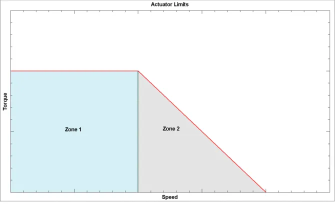
TPAF and OPAF: correspond to translational and orientation amplification factors, respectively.
WTPAFDWS: is the worst value of TPAF over DWS, i.e. the maximum value.
ILA and PLA: are respectively the isotropic and peak linear accelerations starting from rest, and in the absence of any external non‐gravitational wrench.
In this chapter:
Available literature is rich with parallel manipulators (PMs), and some have found their way into industrial applications. However, the number of parallel kinematic machines (PKMs) that has been implemented so far is still very low. This poor exploitation is due to several reasons. In this chapter, an overview on the state of art of PMs and available industrial PKMs will be exposed, highlighting the problematics that hinder their widespread. In addition, the available literature on performance evaluation of manipulators will be discussed, emphasizing the major limitations encountered in the case of robots with heterogeneous degrees of freedom (dofs) and/or with redundancy (whether of actuation or kinematic type). This latter problematic is crucial as the synthesis of both, the architecture and its geometrical dimensions, are supposed to be based on solid criteria well interpretable and that fit machine tool basic requirements. Starting from the aforementioned points, the thesis problematics will be clarified by the end of the chapter and the approach to overcome them will be outlined.
1.1‐ Generalities and Definitions
1.1.1‐ A Brief History on the First Parallel Robots and Parallel
Kinematic Machine Tools
In most articles, it has been reported that the first PMs were the tyre‐testing machine of (GOUGH & WHITEHALL, 1962) (see Fig. 1‐1) and the flight simulator of (STEWART, 1965). However, according to (BONEV, 2003), the first PM perhaps dates back to 1931 (GWINNETT, 1931) and it has been proposed as an amusement device; but it is not known whether the aforementioned architecture has been built or not. Nevertheless, it is undeniable that Gough‐ Stewart platforms have played an essential role in popularizing PMs and inspiring new ones. Actually, parallel robots at their earlier beginnings, were of full mobility1 and mainly based
on the Gough‐Stewart architectures. As for the trend towards lower mobility2 parallel
mechanisms, it can be traced back, according to (ANGELES, 2004), to the work of (HUNT, 1983) and after which planar, spherical, and later spatial mechanisms have been synthesized.
Moreover, another remarkable milestone in the world of parallel mechanisms is perhaps the Delta robot introduced by (CLAVEL, 1991) (see Fig. 1‐2). This robot not only has been vastly industrialized, but also it inspired many new ones with similar features.
According to (KRUT, 2003), one can speak of two generations of parallel mechanisms: the first being described by Gough‐Stewart platforms and based upon architectures, while the second being embodied by Delta‐like or lightweight structures. In fact, thanks to the features
1 With six dofs 2 With the number of dofs less than six Fig. 1‐1: Original Gough platform and shortly before its transfer into the British National Museum of Science and Industry in 2000 (Dunlop Tyres).
present in the latter manipulators, such as fixed actuators at the base and lightweight components and parallelograms, exceptional performances with up to 10 m s in speed and 15 g in acceleration can be reached, even more!
This was a very short briefing regarding parallel robots. Concerning machine tools, the first one based on parallel kinematics, as contrasted to the conventional or serial counterparts, was the Variax3 of Giddings & Lewis (see Fig. 1‐3). It has been presented publically in 1994 within
the International Machine Tool Show held at Chicago. It was based on the Gough‐Stewart idea and intended for milling applications. Afterwards, many industries started researching and developing parallel kinematic machine 3 A video regarding this machine is available at: https://www.youtube.com/watch?v=7TowJZQi‐qY . Fig. 1‐2: FlexPicker (ABB Robotics) industrial robot: photo and graph diagram. Fig. 1‐3: Variax parallel kinematics machine tool (Giddings & Lewis).
tools (PKMs) in parallel with university laboratories. Among these PKMs, we mention: H0H600 (Ingersoll), 6X Hexapod (Mikromat), G500 and G1000 (Geodetics), Cosmo Center PM‐600 (Okuma), Tornado 2000 (Hexel), HEXACT (developed by INA and IFW), Hexapode 300 (CMW), Triaglide (Mikron), Quickstep (Krause & Mauser), UraneSX (Renault Automation/Comau), Georg V of IFW (University of Hanover), Eclipse (Seoul National University), etc. In (COMPANY, 2000) and (WECK & STAIMER, 2002), a more elaborate information is presented regarding the history and state of the art of machine tools in general, and PKMs in particular. Later in this chapter, we will expose only a sample of these machines that exhibit some interesting features.
However, despite the increased interest in PKMs, their spread in industrial and machining applications is rather shy, and still conventional or serial kinematic machines (SKMs) are the highly dominant, with PKMs not exceeding research stages. In fact, comparing the number of theoretically synthesized architectures to that of the implemented ones, clearly shows the huge gap between theory and industrial needs. While the higher motion coupling and insufficiency of the processors’ capabilities were a major hinder for PKMs spread before 1994, the present status, where large advancement in electronics yielded highly performant controllers, shows that other constraints have come into the light presenting new challenges and obstacles to overcome. This will become clear by the end of the chapter.
Nevertheless, before going any further in the world of parallel mechanisms, it is indispensable to provide some definitions to clarify their notion and particularities as compared to serial ones, emphasizing the merits and drawbacks of each. These are discussed in the following sections.
1.1.2‐ Serial Robots
The most industrial robots built until now are serial manipulators (SMs). An SM is an open chain formed by a series of links interconnected one to another by an actuated joint. An example of such manipulators is shown in Fig. 1‐4.
While SMs are characterized by large workspaces and being rather simple to deal with regarding control, they suffer from the following drawbacks: High moving masses which limit their dynamic capability; Poor rigidity as a result of the series configuration and which leads to cumulative errors regarding the end‐effector pose; Wear of the power and sensor connections (cables, flexible tubes) and which might lead to hazardous consequences;
1.1.3‐ Parallel Robots
A parallel manipulator (PM) is defined, according to (MERLET, 2006), as a closed‐loop kinematic chain mechanism whose end‐effector is linked to the base by several independent kinematic chains. Examples on such manipulators are those in Fig. 1‐1, Fig. 1‐2, Fig. 1‐3, and Fig. 1‐5.
Such mechanisms have their interesting features that made them suitable candidates to overcome the limitations of SMs. Unfortunately, they are not without their own demerits. In the upcoming subsections, we expose these virtues and hindrances.
A‐ Advantages
In general, PMs are characterized by the following advantages: Fig. 1‐4: Robot IRB 7600‐150 (ABB Robotics): photo and graph diagram. Fig. 1‐5: Hexamove system (OHE Hagenbuch AG): photo and graph diagram. High payload‐to‐weight ratio;
High stiffness due to the parallel structure;
High dynamic capabilities due to small moving masses, especially when the actuators are placed at or near the base;
Improved accuracy due to the parallel structure and in which unlike SMs, the end‐ effector pose errors are non‐cumulative;
Higher proper frequency due to elevated rigidity and therefore, lessened repeatability errors due to the uncontrolled structural oscillations;
Moreover, the possibility of placing the actuators at the base allows for the following additional benefits:
Higher flexibility regarding the choice of motors and/or gearboxes, as their masses do not highly influence the eventual inertia of the robot (particularly the moving inertia);
Reduction of the problems arising from cable connections between the motors, sensors, and controller.
Enhanced cooling of the actuators resulting in reduced errors due to thermal expansions;
Easier isolation of the motors from the possible detrimental environmental conditions that might be present in the workspace (e.g. applications that might require heavy water rinsing).
It is worth emphasizing that the above‐mentioned features might not necessarily be present in all PMs. In fact, the première designs experienced problems of precision and rigidity (KRUT, 2003).
B‐ Inconveniences
Despite the interesting features described above, PMs suffer usually from the following inconveniences:
Reduced workspace and tilting capacity: This results from the parallel structure itself, as the end‐effector workspace is the intersection of the regions permissible by the individual kinematic chains. Another cause of this reduction is the possibility of inter‐ collisions. Additionally, we mention the usually rather complex shapes of the feasible workspaces, especially when internal singularities (i.e. inside the geometrically accessible workspace) exist.
Singularities: Unlike SMs, PMs present, in addition to serial‐type singularities, other singularity types with more subtleties regarding their identification and classification. These singularities are critical and can lead to uncontrollable motion of the platform (end‐effector) or the deterioration of the mechanical system. The avoidance of such singularities constitutes an essential challenge in the design of a PM. This will be discussed in the subsequent part.
The difficulty of having closed‐form solution for the direct geometric model (DGM): This is nowadays less severe as numerical solutions can be implemented without influencing computation time. This is due to the advanced performance of modern controllers. Calibration difficulties whether relative to geometry, elasticity, and/or dynamics: This is
due to the high coupling between the different chains and the large number of parameters involved as compared with SMs.