Open Archive TOULOUSE Archive Ouverte (OATAO)
OATAO is an open access repository that collects the work of Toulouse researchers and
makes it freely available over the web where possible.
This is an author-deposited version published in :
http://oatao.univ-toulouse.fr/
Eprints ID : 19360
To link to this article : DOI:
10.1016/j.wear.2017.07.003
URL :
http://dx.doi.org/10.1016/j.wear.2017.07.003
To cite this version :
Ramirez, Christophe and Idhil Ismail, Andi and Gendarme,
Christine and Dehmas, Moukrane and Aeby-Gautier, Elisabeth and
Poulachon, Gérard and Rossi, Frédéric Understanding the diffusion
wear mechanisms of WC-10%Co carbide tools during dry
machining of titanium alloys. (2017) Wear, vol. 390-391. pp. 61-70.
ISSN 0043-1648
Any correspondence concerning this service should be sent to the repository
administrator:
staff-oatao@listes-diff.inp-toulouse.fr
Understanding the diffusion wear mechanisms of WC-10%Co carbide tools
during dry machining of titanium alloys
C. Ramirez
a,⁎, A. Idhil Ismail
b, C. Gendarme
b, M. Dehmas
b,c, E. Aeby-Gautier
b,d, G. Poulachon
a,
F. Rossi
aaArts & Métiers ParisTech, LaboMaP, Rue Porte de Paris, 71250 Cluny, France
bUniversité de Lorraine, Institut Jean Lamour, Département Science et Ingénierie des Matériaux et Métallurgie (CNRS UMR 7198), Parc de Saurupt, CS 50840, 54011
Nancy Cedex, France
cCIRIMAT, Université de Toulouse, CNRS, INPT, UPS, 4 allée E. Monso, BP 44362, 31030 Toulouse Cedex 04, France d
LABoratory of EXcellence Design of Alloy Metals for low-mAss Structures (“DAMAS” Labex), Université de Lorraine, France
A R T I C L E I N F O
Keywords:Titanium alloy WC-Co Thermal Diffusion Tool wear mechanisms
A B S T R A C T
The diffusion wear between a WC-10%Co tool and a Ti54M titanium alloy was investigated by studying the reaction between both the materials using a diffusion couple and studying their behavior during a machining test. In addition to the scanning electron microscopy (SEM) study, electron probe microanalysis (EPMA) was conducted to quantitatively analyze the chemical composition in the reactive layers after different holding times at 1100 °C. The diffusion couple revealed a rapid formation of TiC carbides at the interface. The layer growth is parabolic and is mainly toward the Ti54M side. The formation of three affected zones was observed. On the tool side, the two affected zones displayed a continuous decrease in the WC content, as well as a significant en-richment in the Co amount with no WC in the Co rich zone and a decrease in the W and C contents. On the Ti54M side, the tool elements diffused into the alloy material, with the diffusion lengths of C and Co being much longer than that of W. The solubilities of C and Co remained low while that of W was almost 8–9 wt%. The WC dissolution and compositional modification caused a degradation in the mechanical integrity of the tool surface, leading to crater damage. The machining experiments validated this mechanism and tool elements could be found in the adhered titanium layer.
1. Introduction
The diffusion wear between the chip and the rake face during ma-chining is an issue that has been widely investigated for metal cutting operations. Most of the studies deal with tool wear in steel machin-ability applications. Different analytical models have been used to study the diffusion process during machining[1–5]. Naerheim et al.[6]used a dynamic model to analyze the wear diffusion during steel machining with a WC-TiC-Co carbide cutting tool. According to them, the elements of the cutting tool like tungsten (W), carbon (C), and cobalt (Co) tend to diffuse into the chip which is continuously renewed. This renewal does not allow a saturation of the diffusing elements at the tool-chip inter-face, which does not stop or decrease the crater wear rate. In another case, Qi et al. [7] showed that during the machining of austenitic stainless steel deoxidized with calcium, the diffusion wear is limited by the formation of an adhering layer, which is composed of inclusions containing Ca mainly and Al and Si. This adhering layer limited the diffusion of the tool elements into the chip and stopped the TiC grains
from being torn out by the chip flow. A quasi-static diffusion model was used to describe the wear. In addition, Bittès[8]showed that the dif-fusion was slower during the machining of improved machining steel than during the machining of standard steel. In this case, the experi-ments were conducted with identical cutting parameters for two min-utes. It was found that the choice of the machining time could minimize the cratering effect of the rake face.
In the case of the titanium alloys, the machinability depends on the nominal chemical composition, microstructure (grain size, phase frac-tion, texture, etc.), and mechanical properties[9,10]. In addition to these properties, the machining speed plays a key role in determining the machinability[11]. In particular, the machining process is known to generate both thermal and mechanical stresses. The friction between the tool and the specimen during machining causes a rapid increase in the temperature to a value greater than the β transus temperature, and leads to the adhesion of a Ti layer on the carbide tool[12,13]. This creates a problem as titanium has poor thermal conductivity, and the thermal energy cannot be dissipated quickly through the chips. The
http://dx.doi.org/10.1016/j.wear.2017.07.003
Received 12 February 2017; Received in revised form 2 July 2017; Accepted 3 July 2017
⁎Corresponding author.
diffusion of elements (W, C, Co) from the tool to the work material is thought to be the source of wear and hence the degradation in tool life
[9,14]. Furthermore, titanium is known to be chemically reactive with
atmospheric gases such as oxygen at high temperatures, as well as with some elements like carbon. Upon reaction with carbon, titanium forms hard compounds on the alloy surfaces[15], resulting in the wear of the tool rake. This process is initiated by the diffusion of carbon from the tool to the work material and is followed by a reaction with Ti atoms to form a TiC layer[16]. According to Arvieu et al.[17], the evolution of the TiC layer can occur from 400 °C. This issue is mentioned in almost every research paper that deals with the machining of Ti alloys
[18–25], but the information regarding the chemical composition at the
interface between the tool and the work material is mostly qualitative
[16,26,27]. Only a few researchers have worked toward understanding
these mechanisms. Hartung et al.[28]shed light on this problem by demonstrating that a stable titanium carbide layer (TiC) with a depth of 100 nm was formed between the chip and the tool, and this layer minimized the wear by diffusion. The diffusion mechanism during machining was mainly studied by applying a compression load at high temperatures on the titanium alloy and the carbide tool[16,27,29–31]
and by qualitatively analyzing the resulting compounds using electron dispersive X-ray analysis (EDX) and X-ray diffraction (XRD). Several studies[16,29,31]highlighted the presence of two layers at the inter-face; these two layers have been identified as TiC and the η-phase (M6C or M12C). The η-phase is a brittle material, which can form very quickly under mechanical loading[32,33]. The high mechanical stresses acting on the tool-chip interface can play the role of a mechanical activator, and when coupled with high temperatures, enable a faster diffusion.
As described earlier, diffusion wear is an important issue in titanium alloy machining but it is scantily understood. This paper aims at un-derstanding the diffusion process in titanium alloys, using static diffu-sion tests and a quantitative analysis of the diffudiffu-sion layers by the EDX and EPMA techniques, which have never before been used for this type of tool-alloy couple. A comparison of the analyses with machining tests is discussed in the second part of the paper.
2. Materials and methods 2.1. Materials
The titanium alloy used in this work (TMETAL® 54 M (Ti54M)) was provided by TIMET Savoie. The Ti54M titanium alloy was designed to have comparable mechanical properties with the standard Ti6Al4V and better machinability[9,34]. The chemical composition of the alloy in its as-received state is given inTable 1. The Ti54M alloy contains mo-lybdenum, which makes it more β stabilized than Ti6Al4V and de-creases its β transus temperature (950 °C against 1000 °C for Ti6Al4V). Regarding the tool material, tungsten carbide (WC-10%Co) was chosen for the couple diffusion tests. This type of carbide is generally used for the machining of titanium alloys and particularly for drilling operations. It is composed of 90 wt% tungsten carbide (WC) and 10 wt % cobalt. Its K40UF grade confers an ultrafine microstructure with a 0.6 µm diameter for carbide grains. This fine microstructure allows the tool to have high hardness, toughness, and bending strength.
2.2. Diffusion couple
An innovative interdiffusion experiment was designed to yield an understanding of the mechanisms behind the diffusion wear in the tool-alloy couple. A stack consisting of 12 mm diameter discs of Ti54M and WC-Co were placed in a Ti54M crucible and screwed down using a pressure of 120 MPa as shown inFig. 1. To avoid contamination during the diffusion process, the crucible and the screw were made of same alloy (Ti54M). The crucible and the screw sealed the sample against any residual oxygen in the vacuum furnace. Moreover, the dimensions of the whole sample (including crucible and screw) were designed such that after cutting it in half, it fitted entirely within a resin of 22 mm maximum diameter. This allowed us to maintain the stack at similar conditions for heat treatment and further preparation, microstructural analysis as well as to avoid separation between the tool and the tita-nium alloy at the interface.
To achieve an intimate contact between the titanium alloy and tungsten carbide discs, and facilitate the chemical reaction between them, the surfaces of the discs were polished to obtain surface rough-ness (Sa) values of 21.35 nm and 2.79 nm for the Ti54 M alloy and tungsten carbide, respectively. These discs were then stacked one upon the other, and the roughened surfaces increased the area of contact.
The diffusion couple was heated at a rate of 10 °C·min−1in the range of 800–1100 °C and isothermally held at the chosen temperature for different times. The reaction between the two materials was studied and the effect of the cutting time or cutting length on the tool life was analyzed. Four holding times were chosen: 0 min (reference time), 15 min, 30 min, and 2 h. The isothermal holding temperature was se-lected to be 1100 °C. Indeed, according to the cutting conditions during the machining operation, the temperature at the cutting edge can reach up to 800–1100 °C[23,35–37]. This temperature is higher than the β transus of the material (Tβ= 950 °C). Air cooling is carried out at a cooling rate of 360 °C·min−1.
2.3. Machining test
A machining wear test was conducted and the obtained results are compared to those obtained from the diffusion couple. As the present study was realized in the frame of a collaborative project centered on the titanium drilling for the aeronautic industries, the conditions used for these wear tests were based on the cutting conditions used by the manufacturer. The tool used was a non-coated WC-Co tool (Fig. 2) with the same composition as the WC-Co discs used in the diffusion couple. Its rake and flank angles were 30° and 15°, respectively, whereas the average radius of the cutting edge was 18 µm. The cutting angles re-present the angle of the drill tool at the tool corner, which is the most important part of the drill on diffusion issue. The test was conducted in a dry environment with a cutting speed of 30 m·min−1and a feed rate of 0.1 mm·rev−1, which are the cutting speed and the feed rate per tooth during drilling operation. The cutting conditions are summarized
inTable 2.
The wear during the experiment was continuously monitored. The variation in the cutting force was measured using a piezoelectric dy-namometer on which the tool was mounted (Fig. 3), while the cutting temperatures were measured using a thermocouple located 2 mm be-hind the cutting edge. The measurement uncertainty does not exceed 5% in the whole tests. The wear of the cutting edge and the flank face was examined after every trial using an optical microscope. A high-speed camera was used to observe the chip formation. The time of each cutting test was approximately 15 s.
2.4. Structural and microstructural characterization
The various phases in the tool material were identified using a D8 Advance XRD machine. The XRD pattern of the tool material was fur-ther processed by implementing the Rietveld method to extract Table 1
Chemical composition of the Ti54M titanium alloy (wt%).
Chemical composition
Al V Mo Fe O N Ti
quantitative information about each phase.
Three couple diffusion specimens were characterized to ensure the repeatability. The diffusion couple specimens were cut in half without separation and embedded in a conductive resin, as shown inFig. 1b. This conductive resin coating facilitated further characterization by SEM and EPMA. Prior to the microstructural characterization, normal metallographic routines consisting of a multi-step mechanical polishing were carried out to achieve a mirror like surface.
The microstructure of the specimens was analyzed using the SEM FEG Quanta 650 machine equipped with an EDX detector. The APHELION software package was used to analyze the backscattered electron (BSE) micrographs obtained using SEM, to quantify the surface phase fraction.
An EPMA instrument (Jeol JXA 8530F) was used to quantitatively analyze the chemical composition of the specimens. The spectra ob-tained at an accelerating voltage of 15 kV were compared with those of the pure elements. A PAP matrix correction procedure was applied and the counting time for each element (between 50 s and 100 s) was ad-justed to not exceed a relative error of 0.5 wt%. Moreover, EPMA line scans with a 2 µm step were run across the diffusion couple.
3. Results
3.1. Initial state of the couple material
An SEM micrograph of the Ti54M alloy in its as-received state is shown inFig. 4. The β phase is brighter owing to its higher vanadium content, whereas the α phase is dark-grey. A duplex microstructure is observed with nodular α grains, surrounded by a mixture of lamellar α grains and the remaining β phase.
The surface fraction of the β phase, as determined by image analysis on at least 50 SEM images, was found to be 20%. The nodular α phase (46%) has an apparent mean equivalent diameter ranging from 7 to 12 µm, and the lamellar α phase (34%) has an apparent thickness ranging from 1 to 2 µm.
Fig. 5a shows a typical SEM micrograph of the as-received tool
material. The WC particles appear irregularly shaped, with sharp edges, and are surrounded by the Co-rich phase (dark in color). A precise
quantitative chemical analysis of the particles was not attempted owing to their small size. The X-ray diffractogram of the tool material in
Fig. 5b displays several diffraction peaks. The XRD patterns were
ana-lyzed using the Fullprof software with the Rietveld method to de-termine the mass fraction of the WC- and Co-rich phases. The structural model used for the Rietveld refinement was based on the following structural data: a hexagonal structure with P m6 2 space group for tungsten carbide (a = 0.2907 nm and c = 0.2838 nm) and a hexagonal structure with P6 /3mmc space group for the Co-rich phase (a =
0.252 nm and c = 0.410 nm). The quality of the refinement was con-firmed by a visual examination of the plotted difference between the measured and calculated profiles as shown inFig. 5b and by the re-liability factor Rwp, which was lower than 10. The mass fraction of WC particles was found to be 89%.
3.2. Microstructural and chemical analysis of the diffusion couple
Fig. 6displays the SEM images of the WC-Co tool–Ti54M titanium
alloy bonded joints for several heat treatment cycles. It was observed that diffusion bonding took place at all holding times at 1100 °C. It can be noticed from the SEM images that the diffusion interface area does not contain any discontinuity and void. Cracks can be observed mostly along the tool side and several fine precipitates appear in the titanium alloy side on the junction. To understand the presence of these fine precipitates, it is necessary to determine their crystallography and their chemical composition, which can only be achieved by transmission electron microscopy. This scale of observation is out of the scope of the Fig. 1. Principle of the diffusion test: a) Samples in the furnace for diffusion test, b) The cut sample coated with conductive resin.
Fig. 2. a) WC-10%Co cutting tool used in this study, b) thermo-couple instrumentation of the tool.
Table 2
Cutting parameters for the machining test.
Tool material Non-coated WC-10%Co
Rake Angle γn 30° ± 0.1°
Flank angle αo 15° ± 0.1°
Cutting edge radius rβ 18 ± 2 µm
Lubrication Dry
Cutting speed Vc 30 m min−1
Feed rate f 0.1 mm rev−1
paper. Moreover, three of the four distinct diffusion layers can be ob-served at the diffusion interface area, regardless of the holding time as shown inFig. 7.Table 3lists the average chemical composition in the three layers as measured by EPMA at random points (at least 10 mea-suring points) in the diffusion couple subjected to a 2 h holding time.
The first layer, observed near the tool side, was characterized by a decrease in the WC surface fraction and a morphological change characterized by large spaces between the tungsten carbide domains. This layer is called the ‘affected zone’ throughout this paper. After a holding time of 2 h, the contents of W, Co, and C in this region varied largely from 78 to 86 wt%, 6–13 wt%, and 5–7 wt%, respectively. These local variations are most likely due to the different probe points on the layer.
The second layer was also observed near the tool side. At this ob-servation scale, this layer seemed to consist of a Co-rich phase only. An increase in the Co content could easily be measured in the layer after a 2 h holding time. However, the measurements are probably deficient in cobalt due to the lateral resolution limit of the instrument, which is insufficient when compared to the thickness of the layer.
The third layer is formed at the interface of the affected zone and the titanium alloy. According to EPMA analysis, this continuous layer was found to be titanium carbide (TiC) that grows as a single crystal at the interface. The average carbon content in the TiC layer is about 15.5 wt%, indicating a nonstoichiometric state. A 0.5 wt% of W and traces of Co, V, and Al (contribution of the adjacent layers) were also measured inside the TiC layer.
The thickness of the different layers was also measured over the length of the interface. The average thickness is given in theTable 4
with a standard deviation of ± 20%. The average thickness of the layers (mainly 1 and 3) increases upon increasing the holding time. At the beginning of the isothermal exposure, the average thickness of each layer is already significant with values of 3.3, 0.6, and 1.4 µm for the
affected zone, the Co-rich phase, and the TiC layer, respectively. The isothermal holding at 1100 °C caused further TiC growth and the average thickness of the TiC layer increased. Consequently, the average thickness of the affected and Co-rich zones increases due to the diffu-sion of carbon towards the TiC layer. After holding for 2 h, the average thicknesses of the affected zone, the Co-rich zone, and the TiC layer were 7.7, 1.1, and 5 µm, respectively.
The last zone is the interface area, which is located on the Ti54M alloy side. Considering the microstructure, the lamellar α phase is clearly much finer in this area close to the TiC layer, as shown inFig. 8. The thickness of this reaction layer increases when the holding time is increased. It has to be kept in mind that the diffusion of W, Co, and C atoms from the tool material towards the Ti54M alloy takes place in the βphase (at 1100 °C). An increase in the W and Co content may be expected, as both of them are β-stabilizing elements. The increase in C is low due to the poor solubility of C in the β phase.Fig. 9displays the solute distribution of W, Co, C, Ti, Al, and V in the TiC layer towards the center of the Ti54M alloy disc. Note that elements such as O and N were Fig. 3. Experimental setup of the machining trials.
Fig. 4. Duplex microstructure of the as-received Ti54M alloy.
Fig. 5. a) Microstructure of the tool material, b) X-ray diffraction pattern of the tool material and comparison with the calculated pattern.
not examined due to the lack of precision in the EPMA analysis. Whatever be the holding time, sharp tungsten profiles were ob-served with a significant amount of W close to the interface, in com-parison to the other elements in the tool, as shown in Fig. 9a. The
tungsten content at the interface varied between 6 and 8 wt% at various holding times; the variation in the obtained values could be attributed to the irregularities in the interface. The W content gradually decreases Fig. 6. Cross sectional SEM micrographs of the diffusion couple specimens obtained after different holding times at 1100 °C: a) no holding period, b) 15 min, c) 30 min, and d) 2 h.
Fig. 7. Cross sectional SEM micrograph of the diffusion couple after a holding time of 2 h at 1100 °C.
Table 3
Chemical composition (wt%) measured by EPMA at different locations on the diffusion couple after holding for 2 h at 1100 °C.
Layer C W Co Ti Al V
Affected zone 5–7 78–86 3–13 0 0 0 Co-rich phase 3.5 77 19 0.5 0 0 TiC 15.5 0.5 trace 83.6 trace trace
Table 4
Average thickness of the diffusion layer affected zones as a function of the holding time. 0 min 15 min 30 min 2 h.
Affected zone (µm) 3.3 4 5.8 7.7
Co-rich zone (µm) 0.6 0.4 0.5 1.1 Adhesion zone -TiC (µm) 1.4 2.3 3.8 5
Fig. 8. SEM micrograph of the TiC-Ti54M interface after holding at 1100 °C for 2 h. C. Ramirez et al.
as the distance from the interface increases. Increasing the holding time enabled W to diffuse over larger distances in the titanium alloy. The contents of C and Co were relatively constant over the analyzed dis-tance (100 µm). The C and Co contents ranged in between 0.5–0.6 wt% and 0.2–0.6 wt%, respectively. The content of titanium, aluminum, and vanadium decreases continuously as one moves closer to the interface. Some fluctuations in the solute distribution in the titanium alloys away from the interface can also be observed due to the partitioning of Al, V, and Co elements during the β− > α phase transformation on cooling and the coarse morphology of the lamellar α grains. No fluctuation in the solute distribution could be observed close to the interface due to
the finer morphology of the lamellar α phase. 3.3. Machining test results
The phenomena observed in the diffusion couple experiment can be seen in the machining test as well. That is why a comparison was made between the diffusion couple test and the machining operation. The typical signals acquired during a machining trial are presented in
Fig. 10. It must be noted that the cutting temperature does not reach the
steady state during the first trial; on the other hand, the cutting force remains constant during machining.
10 20 30 40 50 60 70 80 90 100 0 1 2 3 4 5 6 7 8 9 10 Distance (µm) Chemical composition (wt. %) W Concentration profile a) No holding 15 min. 30 min. 120 min. 10 20 30 40 50 60 70 80 90 100 0 1 2 3 4 5 6 7 8 9 10 Distance (µm) Chemical composition (wt. %) Al Concentration profile e) No holding 15 min. 30 min. 120 min. 10 20 30 40 50 60 70 80 90 100 0 1 2 3 4 5 6 7 8 9 10 Distance (µm) Chemical composition (wt. %) C Concentration profile b) No holding 15 min. 30 min. 120 min. 10 20 30 40 50 60 70 80 90 100 0 1 2 3 4 5 6 7 8 9 10 Distance (µm) Chemical composition (wt. %) Co Concentration profile c) No holding 15 min. 30 min. 120 min. 10 20 30 40 50 60 70 80 90 100 0 1 2 3 4 5 6 7 8 9 10 Distance (µm) Chemical composition (wt. %)/10 Ti Concentration profile d) No holding 15 min. 30 min. 120 min. 10 20 30 40 50 60 70 80 90 100 0 1 2 3 4 5 6 7 8 9 10 Distance (µm) Chemical composition (wt. %) V Concentration profile f) No holding 15 min. 30 min. 120 min.
Fig. 9. Solute distribution on the titanium alloy side of the diffusion couple after heat treatment at 1100 °C for different holding times: a) tungsten, b) carbon, c) cobalt, d) titanium, e) aluminum, and f) vanadium.
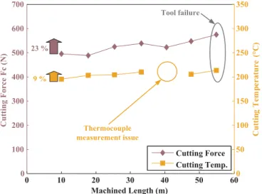
The cutting force and the cutting edge temperature are depicted as functions of the machined length (number of trials) inFig. 11. A sig-nificant increase of almost 23% is observed in the cutting force between the first and the last trials, this leads to catastrophic tool wear resulting from the chipping of the tool edge, as shown inFig. 11. However, the cutting temperature increased by only 9%, which is 2.5 times less than the increase in the cutting force. Nevertheless, the average temperature of 200 °C as measured by the thermocouple located 2 mm behind the cutting edge allows us to assume that the temperature at the cutting edge is very high and can reach the temperatures reported in the lit-erature[23,35–37].
The high cutting temperature at the cutting edge resulted in thermal damage, underlined by the orange line inFig. 12. A change in the color of the surface, a typical occurrence due to surface oxidation, is observed on the flank face of the tool. The cutting edge undergoes chipping at the locations where the contamination is prominent. In addition, the high temperatures lead to the bonding of titanium on the edge and the rake face (Figs. 12 and 13). Such sticky layers confirm the occurrence of a chemical reaction between the tool material and the machined material (titanium alloy).
After the machining process, the tool was subjected to SEM analysis to study the morphological features. Furthermore, a metallurgical analysis was conducted on the tool by EDX to determine if some dif-fusion occurred between the tool and the machined material and to
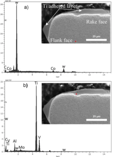
compare the results with the one obtained for the diffusion couple. SEM micrograph and EDX analyses of the tool were performed to investigate if the diffusion of the elements occurred during machining as shown onFig. 13. Three zones can be clearly observed in the SEM micrograph. The first zone corresponds to a Ti layer, which is observed on the rake face up to a 400-µm length in the entire contact zone be-tween the chip and the tool. This feature is similar to the one reported earlier[26]. The deposition and smearing of the Ti alloy was depicted by the Ti build-up edge (BUE) on the rake and flank edges. The Ti BUE creates an uneven and sluggish surface around the rake edge. As a re-sult, the contact between the flowing chip and the rake face is minimum. The contact resumes when the adhered Ti on the rake edge breaks away[40]. The elemental composition of the smeared Ti alloys was identified by EDX, as shown inFig. 13.
The EDX revealed a distinct separation between the tool zone that contains the W, C, and Co elements and the build-up of the titanium rich layer. A crater wear can be observed on the surface edge of the rake face, with dimensions of roughly 5 × 10 µm, which are much smaller than the crater wear reported in the literature[9,30]. On the one hand the size discrepancy is certainly due to mechanical chipping. On the other hand, the crater is surrounded by a worn area that originated from the breakup of the adhered Ti. The presence of W is clearly noticed in the EDX spectrum of the Ti layer (Fig. 13b). The Co peak could not be clearly detected in the adhered titanium inFig. 13b. This does not imply that no Co diffuses toward the Ti side. The low intensity is caused by a smaller content of this element and thus its concentration is em-bedded in the measurement noise. As a reference, the peak intensity that arises from 10 wt% Co in the tool can be seen in theFig. 13a. No presence of titanium could be detected in the tool (Fig. 13a). 4. Discussion
4.1. Diffusion couple tests
The chemical composition analysis by EPMA revealed the chemical interaction between the tool and the Ti alloy. Different layers could be observed in the WC-Co sample: the affected zone and the Co-rich zone characterized by a decreasing content of the WC carbides, W, and C, and an enhanced content of Co in the Co-rich area. Some traces of Ti were also identified in the Co-rich area. The TiC layer consisted mainly of Ti and C, along with a small amount of W (0.5 wt%). Traces of Al and V could be noticed. Moreover, the diffusion of W, Co, and C was also clearly noticeable in the Ti matrix.
W and Co are substitution β stabilizing elements in Ti alloys, and hence, their diffusion towards the Ti matrix is favored. C is an inter-stitial element for Ti alloys. It has a poor solubility in both the α and β phases and it diffuses rapidly as compared to the substitution elements (W and Co). Its presence in a Ti matrix will rapidly lead to the formation of TiC.
The presence of a TiC layer in the diffusion couple specimen just heated up to 1100 °C implies that its nucleation and growth occurred rapidly on heating, even at low temperatures. Literature reports that the diffusion of Ti from the Ti alloy to the tool may start from 400 °C[27]. This can explain why the TiC layer consists of numerous TiC pre-cipitates with different sizes and strongly indicates that the TiC layer in the diffusion couple forms in the early stages during heating. The TiC particles nucleate at the interface between the tool and the Ti alloy and grow mainly toward the Ti alloy. The coarse grains of TiC led to a rough interface between TiC and the titanium alloy.
The formation of TiC implies diffusive processes with a diffusion of C towards the Ti alloy and a reaction of Ti atoms with C atoms. It implies the dissolution of WC particles and consequently, a decrease in the WC content of the tool material is observed when moving from the bulk towards the front of the TiC/tool interface.
The growth of TiC in the Ti matrix is due to the fact that the dif-fusion process between the tool and the Ti alloy is mainly controlled by
0 10 20 30 40 50 0 100 200 300 400 500 600 700 Time (s) C ut ti ng F or ce F c ( N ) 0 50 100 150 200 250 300 350 C ut ti ng T em pe ra tu re ( °C ) Cutting Force Cutting Temp. Cutting Force Cutting Temp.
Fig. 10. Reference signals of the cutting force and temperature, acquired during a ma-chining trial. 0 10 20 30 40 50 60 0 100 200 300 400 500 600 700 Machined Length (m) Cutting Force Fc (N) 0 50 100 150 200 250 300 350 C ut ti ng T em pe ra tu re ( °C ) Cutting Force Cutting Temp. 9 % 23 % Thermocouple measurement issue Tool failure
Fig. 11. The evolution of cutting force and temperature evolution as functions of the machined length.
the diffusion of carbon at the initial stage (its diffusivity is far greater than that of Ti[42,43]). However, as no pile up of Al and V of the β phase (1100 °C) is observed in front of the TiC/β, it can be considered that the growth rate of the TiC layer is relatively low as compared to the diffusivity of Al and V. The formation of the TiC layer also led to the formation of a Co-rich zone. Indeed, WC dissolution occurred and the very rapid diffusion of C toward TiC as well as the significant diffusion of W, led to an increase in the Co content. In this layer, no η precipitates were observed as compared to Hatt's results that reported a mixture of W, Co, and M6C (η-phase) in this zone[31].
The TiC layer in the tool-Ti54M titanium alloy bonded interface area acts as a diffusion barrier, since it limits the diffusion of elements from the tool to the titanium matrix. Thus, the TiC grains contain about 0.5 wt% of W and traces of other substitution elements. As a result, the diffusion of the tool elements toward the Ti matrix occurs probably very early on during the heating cycle. No complete thermodynamic de-scription of the Ti-W-Co-C system is given in the literature. However, it has been reported that the thermally activated diffusion in the Ti-W system starts roughly at 600 °C[41]. The complete miscibility of W in the β phase for the Ti-W system can explain the high content of W in the Ti alloy in front of the TiC/Ti alloy interface. The contents of C and Co in the Ti alloy in front of the TiC/Ti alloy interface are clearly lower than that of W. For C, the measured content is about 0.5–0.6 wt%, which is in the range of the solubility limit of C in α-Ti and β-Ti[38]. For Co, the measured value of 0.2–0.6 wt% is much lower than the solubility limit of Co either in the α phase (~ 1.5 wt% at 685 °C) or in the β phase (15 wt% in β-Ti at 1100 °C)[39]. As the amount of Co is much lower than the solubility limit in the β phase at 1100 °C, the precipitation of Ti2Co as hypothesized by Hatt[31]is not probable
because the mean chemical composition of the surrounding trans-formed beta phase is too low.
The EPMA analysis also reveals that both C and Co diffuse much further than W in the Ti54M titanium alloy. This result is in contra-diction with the literature [30], particularly in the case of Co. The calculation done by Zhang et al. indicates that among the three tool elements, Co has the slowest diffusion rate in the matrix. It can be noticed that the TiC layer limits the diffusion of Co drastically, as un-derstood by the presence of only traces of Co in the TiC layer.
In the case of W, its content in the Ti matrix remains relatively constant at the TiC/Ti interface at different holding times. We can thus assume that a local equilibrium was achieved. Moreover, the char-acteristic diffusion length of W in the Ti alloy was found to increase with the holding time. The diffusion coefficient of W in the Ti matrix was estimated from the diffusion profiles considering a simple one-di-mension model. The diffusion is considered to occur in a semi-infinite medium with a constant W concentration at the interface between TiC and the Ti alloy. The concentration variations are expressed by the following equation[44]: = − c x t c erf x Dt ( , ) (1 ( 2 )) s (1) where c(x,t) denotes the concentration at distance x and run time t, cs the concentration at the TiC/Ti alloy interface in Ti alloy, x the dis-tance, t the run time and D the diffusion coefficient. The diffusion coefficient at 1100 °C can be determined from the slope of the
−
−
erf 1[(cs c x t( , ))/ ]cs plots as a function of the distance (x). Fig. 14
shows the inverse error function plots vs. x at the holding times of 30 min and 2 h. The measurements of the concentration-distance Fig. 12. Thermal and mechanical damage on the flank face versus machining length.
profiles were corrected by subtracting the concentration profile devel-oped for a 0 min holding time. The cooling rate was fast enough to consider that the chemical exchange during this step was negligible. For both holding times, the relationship obtained is linear with no deviation from the ideal behavior, this is due to the presence of large amounts of grain boundaries and dislocations (both of which can provide fast dif-fusion paths). The diffusion coefficients determined from the slopes equal to(2 Dt)−1are quite similar (1 × 10–14m2s−1for 30 min and 3
× 10–14m2s−1for 2 h). This finding suggests that the outward diffu-sion of W from the tool is not dependent on the continuous thickening of the TiC layer until up to 5 µm. Moreover, the diffusion coefficient in the Ti matrix is one order of magnitude lower than the diffusion coef-ficient in the tool as reported in the literature (about 3 × 10–13m2s−1 at 1100 °C[30]). The lower value obtained in the matrix may imply that the diffusion of W in the TiC layer may decrease the entire W diffusion flux, and consequently limit the changes in the tool compo-sition and damages and endow the TiC interface with a diffusion barrier character.
The finer microstructure observed in the Ti matrix near the TiC interface indicates a lower precipitation temperature of the α phase. As the cooling rate can be considered similar, this difference is associated with the local chemical composition. The presence of C, Co, and W in the titanium matrix is expected to modify the β transus temperature, as well as the kinetics of the α precipitation on cooling. The β transus temperature increases upon increasing the C content, while increasing W and Co contents will decrease it. On the basis of thermodynamic calculations performed with the ThermoCalc software and binary sys-tems, the β transus temperature was found to decrease by 5 °C/wt% for W and 25 °C/wt% for Co, while it increased by 100 °C/wt% for C. Even if we cannot conclude about the absolute value of Tβ, we can claim that for the considered area the Tβis the lowest near the interface area. Indeed, the C and Co contents are nearly constant over 100 µm, while the W content decreases. The thickness evolution of the α lamellae is associated with the W gradient, i.e. to a lower local Tβand certainly slower kinetics of the α formation.
4.2. Machining tests
The phenomena observed in the diffusion couple experiment can be seen in the actual machining test. The presence of the tool elements occurs in the titanium layer adhered on the tool. The W and C elements can be detected in the adhered titanium layer, thus confirming their diffusion. However, the Co peak could not be clearly detected in the adhered titanium. The EDX scans from the top of the rake face and its cross section lead to the detection of low to no presence of Co, as de-picted inFig. 13. This does not imply that no Co diffuses toward the Ti side. The low intensity is caused by a smaller content of this element and thus its concentration is embedded in the measurement noise. As a reference, the peak intensity that arises from 10 wt% Co in the tool can be seen in theFig. 13a.
The diffusion couple tests under different isothermal holding con-ditions also provide important information on the practical aspects of machining. It has been shown that a long holding time increases the size of the diffusion affected area, for both the Co-rich phase and the transformed carbide zone.
The translation of the diffusion couples results to the machining process shows that the phenomenon of diffusion can interfere on the tool wear depending on the machining time and high cutting tem-peratures. Moreover, the plastic deformation associated with the ma-chining process can drastically enhance the diffusion. Such conditions promote the diffusion of tool elements, modify the chemical composi-tion of the tool, and eventually will deteriorate the mechanical integrity of the tool surface.
5. Conclusions
The diffusion couple experiments and the comparison with the machining test allow us to make several conclusions:
•
The titanium matrix and the tool react very rapidly, even during the early stages of heating, resulting in the formation of TiC precipitates at the interface between the tool and the Ti alloy.•
On the tool side, the decreasing WC gradient was characterized by an additional zone near TiC, free of WC and rich in Co. Poor/no Fig. 13. EDX analysis at different damage areas of the rake face after machining. Theinsets show the microstructure of the tool cross section with the corresponding points where the EDX was acquired: a) the tool zone and b) adhered Ti zone.
0 10 20 30 40 50 60 70 80 0 0.5 1 1.5 2 2.5 Distance (µm) 30 min. 120 min. (2√Dt)-1
Fig. 14. Plots of the inverse error function vs. distance from the TiC/Ti alloy interface (x), from the data reported inFig. 9for 30 min and 2 h holding times at 1100 °C. The linear relationship leads to the W diffusion coefficient.
diffusion of the solutes in the Ti matrix was noticed.
•
On the titanium alloy side, Co and C diffused over a distance of more than 100 µm, while W diffused only over 70 µm (2 h holding time). The diffusion of W in the TiC layer is proposed to be a limiting step for the degradation of the tool.•
After the machining test, the presence of W in the deposited Ti was observed. However, the EPMA analysis could not validate the pre-sence of TiC or Co because their concentration is extremely small, and their signals are embedded in the measurement noise.•
The enrichment and gradient composition of W, Co, and C in the Ti matrix lead to a modification of the local β transus temperature and consequently to a gradient in the thickness of the α lamellae. AcknowledgementsThe authors would like to thank The French National Research Agency (ANR) for funding this research and also Airbus Group Innovations, TIMET Savoie, and Seco Tools for their technical and material support. The authors are grateful to everyone who contributed to this research, including the technicians who helped to implement the various experiments and analyses.
References
[1] N.H. Cook, P.N. Nayak, The thermal mechanics of tool wear, J. Manuf. Sci. Eng. 88 (1966) 93–100.
[2] A. Bhattacharyya, A. Ghosh, Diffusion wear of cutting tools, CIRP Ann. - Manuf. Technol. 16 (1967) 369–375.
[3] T.N. Loladze, Of the theory of diffusion wear, CIRP Ann. - Manuf. Technol. 30 (1981) 71–76,http://dx.doi.org/10.1016/S0007-8506(07)60898-1.
[4] J. Kannatey-Asibu E, A transport-diffusion equation in metal cutting and its appli-cation to analysis of the rate of flank wear, J. Eng. Ind. 107 (1985) 81–89,http:// dx.doi.org/10.1115/1.3185971.
[5] A. Molinari, M. Nouari, Modeling of tool wear by diffusion in metal cutting, Wear 252 (2002) 135–149,http://dx.doi.org/10.1016/S0043-1648(01)00858-4. [6] Y. Naerheim, E.M. Trent, Diffusion wear of cemented carbide tools when cutting
steel at high speeds, Met. Technol. 4 (1977) 548–556,http://dx.doi.org/10.1179/ 030716977803292673.
[7] H.S. Qi, B. Mills, On the formation mechanism of adherent layers on a cutting tool, Wear 198 (1996) 192–196,http://dx.doi.org/10.1016/0043-1648(96)80023-8. [8] G. Bittès, Contribution à la connaissance des mécanismes fondamentaux liés à
l′usinabilité des aciers de construction mécanique, Université de Toulon, 1993. [9] M. Armendia, A. Garay, L.-M. Iriarte, P.-J. Arrazola, Comparison of the
machin-abilities of Ti6Al4V and TIMETAL® 54M using uncoated WC–Co tools, J. Mater. Process. Technol. 210 (2010) 197–203,http://dx.doi.org/10.1016/j.jmatprotec. 2009.08.026.
[10] P.-J. Arrazola, A. Garay, L.-M. Iriarte, M. Armendia, S. Marya, F. Le Maître, Machinability of titanium alloys (Ti6Al4V and Ti555.3), J. Mater. Process. Technol. 209 (2009) 2223–2230,http://dx.doi.org/10.1016/j.jmatprotec.2008.06.020. [11] E.A. Rahim, S. Sharif, Investigation on tool life and surface integrity when drilling
Ti-6Al-4V and Ti-5Al-4V-Mo/Fe, JSME Int. J. Ser. C. Mech. Syst. Mach. Elem. Manuf. 49 (2006) 340–345.
[12] G.A. Ibrahim, C.H.C. Haron, J.A. Ghani, Progression and wear mechanism of cvd carbide tools in turning Ti-6Al-4V ELI, Int. J. Mech. Mater. Eng. 4 (2009) 35–41. [13] J.A. Ghani, C.H. Che Haron, S.H. Hamdan, A.Y. Md Said, S.H. Tomadi, Failure mode
analysis of carbide cutting tools used for machining titanium alloy, Ceram. Int. 39 (2013) 4449–4456,http://dx.doi.org/10.1016/j.ceramint.2012.11.038. [14] E.O. Ezugwu, R.B. Da Silva, J. Bonney, Á.R. Machado, Evaluation of the
perfor-mance of CBN tools when turning Ti–6Al–4V alloy with high pressure coolant supplies, Int J. Mach. Tools Manuf. 45 (2005) 1009–1014,http://dx.doi.org/10. 1016/j.ijmachtools.2004.11.027.
[15] B.K. Subhas, R.A. Katti, Experimental studies on chemical reactivity and dimen-sional growth in machining of titanium alloys, in: Vol 5 Manuf Mater Met. Ceram Struct Dyn Control Diagn. Instrum. Educ. Process Ind. Technol. Resour., ASME, p. V005T11A006. doi: 〈http://https:dx.doi.org/10.1115/84-GT-276〉.
[16] C.M. Moreno, G. Artola, J.M. Sanchez, Interaction between Ti-6%Al-4%V alloys and hardmetals coated by cathodic-arc technology, Mater. Sci. Forum 492–493 (2005) 353–358,http://dx.doi.org/10.4028/www.scientific.net/MSF.492-493.353. [17] C. Arvieu, J.P. Manaud, J.M. Quenisset, Interaction between titanium and carbon at
moderate temperatures, J. Alloy. Compd. 368 (2004) 116–122,http://dx.doi.org/ 10.1016/j.jallcom.2003.08.051.
[18] B.M. Kramer, On tool materials for high speed machining, J. Eng. Ind. 109 (1987)
87–91,http://dx.doi.org/10.1115/1.3187113.
[19] A. Jawaid, S. Sharif, S. Koksal, Evaluation of wear mechanisms of coated carbide tools when face milling titanium alloy, J. Mater. Process. Technol. 99 (2000) 266–274,http://dx.doi.org/10.1016/S0924-0136(99)00438-0.
[20] Z.G. Wang, M. Rahman, Y.S. Wong, Tool wear characteristics of binderless CBN tools used in high-speed milling of titanium alloys, Wear 258 (2005) 752–758,
http://dx.doi.org/10.1016/j.wear.2004.09.066.
[21] M. Nouari, A. Ginting, Wear characteristics and performance of multi-layer CVD-coated alloyed carbide tool in dry end milling of titanium alloy, Surf. Coat. Technol. 200 (2006) 5663–5676,http://dx.doi.org/10.1016/j.surfcoat.2005.07.063. [22] A.K.M.N. Amin, A.F. Ismail, M.K. Nor Khairusshima, Effectiveness of uncoated
WC–Co and PCD inserts in end milling of titanium alloy—Ti–6Al–4V, J. Mater. Process. Technol. 192–193 (2007) 147–158,http://dx.doi.org/10.1016/j. jmatprotec.2007.04.095.
[23] M. Nouari, H. Makich, Experimental investigation on the effect of the material microstructure on tool wear when machining hard titanium alloys: Ti–6Al–4V and Ti-555, Int. J. Refract. Met. Hard Mater. 41 (2013) 259–269,http://dx.doi.org/10. 1016/j.ijrmhm.2013.04.011.
[24] G. Li, M.Z. Rahim, S. Ding, S. Sun, Performance and wear analysis of polycrystalline diamond (PCD) tools manufactured with different methods in turning titanium alloy Ti-6Al-4V, Int. J. Adv. Manuf. Technol. (2015) 1–17,http://dx.doi.org/10. 1007/s00170-015-7949-6.
[25] L. Liang, X. Liu, X. Li, Y.-Y. Li, Wear mechanisms of WC–10Ni3Al carbide tool in dry turning of Ti6Al4V, Int. J. Refract. Met. Hard Mater. 48 (2015) 272–285,http://dx. doi.org/10.1016/j.ijrmhm.2014.09.019.
[26] R.A. Rahman Rashid, S. Palanisamy, S. Sun, M.S. Dargusch, Tool wear mechanisms involved in crater formation on uncoated carbide tool when machining Ti6Al4V alloy, Int J. Adv. Manuf. Technol. 83 (2015) 1457–1465,http://dx.doi.org/10. 1007/s00170-015-7668-z.
[27] D. Jianxin, L. Yousheng, S. Wenlong, Diffusion wear in dry cutting of Ti–6Al–4V with WC/Co carbide tools, Wear 265 (2008) 1776–1783,http://dx.doi.org/10. 1016/j.wear.2008.04.024.
[28] P.D. Hartung, B.M. Kramer, B.F. von Turkovich, Tool wear in titanium machining, CIRP Ann. - Manuf. Technol. 31 (1982) 75–80, http://dx.doi.org/10.1016/S0007-8506(07)63272-7.
[29] A. Ikuta, K. Shinozaki, H. Masuda, Y. Yamane, H. Kuroki, Y. Fukaya, Consideration of the adhesion mechanism of Ti alloys using a cemented carbide tool during the cutting process, J. Mater. Process. Technol. 127 (2002) 251–255,http://dx.doi.org/ 10.1016/S0924-0136(02)00152-8.
[30] S. Zhang, J.F. Li, J.X. Deng, Y.S. Li, Investigation on diffusion wear during high-speed machining Ti-6Al-4V alloy with straight tungsten carbide tools, Int. J. Adv. Manuf. Technol. 44 (2009) 17–25,http://dx.doi.org/10.1007/s00170-008-1803-z. [31] O. Hatt, P. Crawforth, M. Jackson, On the mechanism of tool crater wear during
titanium alloy machining, Wear 374–375 (2017) 15–20,http://dx.doi.org/10. 1016/j.wear.2016.12.036.
[32] T. Tsuchida, N. Morita, Formation of ternary carbide Co6W6C by mechanical ac-tivation assisted solid-state reaction, J. Eur. Ceram. Soc. 22 (2002) 2401–2407,
http://dx.doi.org/10.1016/S0955-2219(02)00016-X.
[33] C.B. Pollock, H.H. Stadelmaier, The eta carbides in the Fe−W−C and Co−W−C systems, Metall. Trans. 1 (1970) 767–770,http://dx.doi.org/10.1007/ BF02811752.
[34] N. Khanna, A. Garay, L.M. Iriarte, D. Soler, K.S. Sangwan, P.J. Arrazola, Effect of heat treatment conditions on the machinability of Ti64 and Ti54 M alloys, Procedia Cirp. 1 (2012) 477–482,http://dx.doi.org/10.1016/j.procir.2012.04.085. [35] M. Kikuchi, The use of cutting temperature to evaluate the machinability of
tita-nium alloys, Acta Biomater. 5 (2009) 770–775,http://dx.doi.org/10.1016/j.actbio. 2008.08.016.
[36] P. Müller-Hummel, M. Lahres, Quantitative measurement of temperatures on dia-mond-coated tools during machining, Diam. Relat. Mater. 4 (1995) 1216–1221,
http://dx.doi.org/10.1016/0925-9635(95)00299-5.
[37] T. Minton, S. Ghani, F. Sammler, R. Bateman, P. Fürstmann, M. Roeder, Temperature of internally-cooled diamond-coated tools for dry-cutting titanium, Int. J. Mach. Tools Manuf. 75 (2013) 27–35,http://dx.doi.org/10.1016/j. ijmachtools.2013.08.006.
[38] ASM Handbook, Volume 3 - Alloy Phase Diagrams, ASM International, 1992, p. 539.
[39] B. Predel, Co-Ti (Cobalt-Titanium), in: O. Madelung (Ed.), Ca-Cd – Co-Zr, Springer Berlin, Heidelberg, 1993, pp. 1–5, ,http://dx.doi.org/10.1007/978-3-540-44756-6_ 168.
[40] W. Min, Z. Youzhen, Diffusion wear in milling titanium alloys, Mater. Sci. Technol. 4 (2013) 548–553,http://dx.doi.org/10.1179/mst.1988.4.6.548.
[41] S.K. Bhagat, T.L. Alford, Texture formation in Ag thin films: effect of W–Ti diffusion barriers, J. Appl. Phys. 104 (2008) 103534,http://dx.doi.org/10.1063/1.3028233. [42] Y. Lv, P. Hodgson, L. Kong, W. Gao, Study of growth mechanism of TiC cluster in ferrite via molecular dynamics simulation, Mater. Lett. 159 (2015) 389–391,http:// dx.doi.org/10.1016/j.matlet.2015.07.039.
[43] F.J.J. van Loo, G.F. Bastin, On the diffusion of carbon in titanium carbide, Metall. Trans. A. 20 (1989) 403–411,http://dx.doi.org/10.1007/BF02653919. [44]J. Crank, The Mathematics of Diffusion, Clarendon Press, Oxford, 1975.