OATAO is an open access repository that collects the work of Toulouse
researchers and makes it freely available over the web where possible
Any correspondence concerning this service should be sent
to the repository administrator:
[email protected]
This is an author’s version published in:
http://oatao.univ-toulouse.fr/26629
To cite this version: Vernouillet, A.
and Vande Put, Aurélie
and Pugliara, Alessandro
and Doublet, S. and Monceau, D.
Metal dusting of Inconel 625 obtained by laser beam melting: Effect
of manufacturing process and hot isostatic pressure treatment.
(2020) Corrosion Science, 174. 108820. ISSN 0010938X
Metal dusting of Inconel 625 obtained by laser beam melting: Effect of
manufacturing process and hot isostatic pressure treatment
A. Vernouillet
a,*
, A. Vande Put
a, A. Pugliara
a,b, S. Doublet
c, D. Monceau
a aCIRIMAT, ENSIACET, Université de Toulouse, CNRS, BP 44362, 31030, Toulouse Cedex 4, FrancebCentre de Microcaractérisation Raimond Castaing, Université de Toulouse, UPS – CNRS – INPT – INSA, 31400, Toulouse, France
cAir Liquide R&D, Centre de Recherche Paris Innovation Campus, 1 chemin de la porte des loges, BP-126, 78354, Jouy-en-Josas Cedex, France
A R T I C L E I N F O
Keywords: Nickel (A) Superalloy (A)
High temperature corrosion (C)
A B S T R A C T
Metal dusting resistance of Inconel 625 alloy obtained by laser beam melting (LBM), compared to wrought alloy 625 was assessed during 9 500 h at 610 °C. Whatever the manufacturing process, the mass variations were very small when the systems were ground thanks to the formation of a uniform protective chromia layer. However, the high surface roughness was shown to be detrimental as the waviness favoured the local formation of an unprotective spinel oxide. Hot isostatic pressure (HIP) treatment recrystallized the alloy and increased its grain size. This reduced chromium diffusion towards the surface, explaining the poorer resistance of the LBM + HIP system.
1. Introduction
Hydrogen is industrially obtained from two main reactions, the steam methane reforming (SMR) reaction and the water gas shift (WGS) reaction. In addition to H2, CO and CO2are produced during this
pro-cess. This leads to the formation of an atmosphere composed of H2, CO,
CO2, CH4and H2O. When exposed to this gas mixture, iron- and
nickel-based alloys may be subjected to metal dusting, a catastrophic form of corrosion by carbon that takes place between 400 °C and 800 °C in highly carburising atmospheres (carbon activity or aC> > 1) with a
low oxygen partial pressure [1,2]. This phenomenon leads to the dis-integration of metallic materials into a dust of fine metallic particles, oxides, carbides and graphitic carbon. When alloys form a protective oxide scale, metal dusting results in pits localised at the defects of the oxide scale.
To intensify the production of hydrogen and reduce the size of the installations, heat exchanges must be improved and smaller reactors built. In order to do so, intricate geometries have been developed that combine counter current small tubes and thin walls to optimize heat exchange. Additive manufacturing techniques and especially power bed fusion enables the construction of such complex geometries. Indeed, this process consists in melting a powder bed in a predetermined pat-tern, using a laser. Another layer of powder is then deposited on top of the melted one and the part is built layer by layer [3,4]. Its shape can therefore be more complex than what can be obtained by forging or
casting, for example.
It is likely that the metallurgical differences induced by the LBM process have an influence on the metal dusting resistance. During the process, the temperature difference between the top and the bottom layer is important. Because of this temperature gradient, the micro-structure is columnar in the building direction, contrary to wrought parts where the microstructure is equiaxed [5]. Moreover, due to the extremely rapid cooling rates in additive manufacturing, precipitates do not form or not in the same proportions as in traditional making methods [6]. Plus, the local nature of the metal dusting attack could be emphasized by the surface defects or inhomogeneities resulting from additive manufacturing.
This work focuses on the metal dusting degradation of a nickel-based alloy, Inconel 625 (In625) obtained by an additive manufacturing technique: laser beam melting (LBM). It also studies the influence of a hot isostatic pressure treatment (HIP) which is a common post-treat-ment for additive manufactured parts in order to reduce the porosity that can be induced by this process.
In625 is reported to have a good metal dusting resistance. Indeed, Young, in a comparative work between different nickel-based alloys, pointed out that In625 was the only alloy that showed no carburisation up until 500 cycles (1 h, 680 °C, mixture of CO, H2O and H2, aC= 2.9)
[7]. Even passed the incubation time, the carbon uptake remained at least 10 times less than that of Inconel 601, 690, 693 and alloy 800. Also Fabas et al. reported no mass variation for Inconel 625, ground
⁎Corresponding author.
E-mail address:[email protected](A. Vernouillet). https://doi.org/10.1016/j.corsci.2020.108820
2. Experimental procedure
The metal dusting experiment was carried out at 610 °C, at a total pressure of 16 bar. The gas mixture was composed of 48%H2
-9%CO-6%CO2-3 %CH4-34%H2O and the gas flow was equal to 8.0 cm.s−1.
The carbon activity (6.9) and the oxygen partial pressure (1.8 × 10⁻²⁴
bar) were calculated using the reaction of reduction of CO (1) and the water decomposition reaction(2)respectively, considering a perfect gas behaviour.
CO + H2= C + H2O (1)
H2O = H2+ ½ O2 (2)
Gas analyses were performed at the outlet of the rig (25 cm long) in order to verify the gas composition. Discrepancies were observed: H2
and CO seemed to be consumed whereas CO2, CH4and H2O seemed to
form within the rig. The carbon activity is therefore between 6.9 (inlet) and 3.4 (outlet) and the oxygen partial pressure between 1.8 × 10⁻²⁴
bar and 2.4 × 10⁻²⁴ bar. These differences in the gas composition
could come from the methanation reaction(3)or the water gas shift reaction(4). These reactions industrially occur in heterogeneous phase. However, in this study the residence time is much longer than in-dustrially, allowing the reactions to occur homogeneously.
CO + 3H2= CH4+H2O (3)
CO + H2O = H2+ CO2 (4)
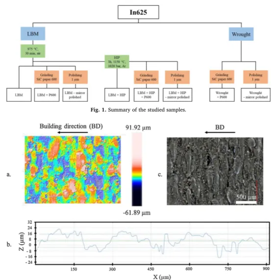
All the samples tested were made of In625. The chemical compo-sition in atomic percent of the wrought In625 is as follows: 61.9 % Ni, 4.2 % Fe, 24.6 % Cr, 2.3 %Nb, 5.6 % Mo, 0.5 % Ti, 0.9 % Al and 62.6 % Ni, 4.0 % Fe, 25.0 % Cr, 2.0 % Nb, 5.9 % Mo, 0.1 % Ti, 0.3 % Al for the as-built additive manufactured In625. The LBM samples were fabri-cated by Poly-Shape (Salon-de-Provence, France) on a SLM 500 of SLM solutions using the standard parameters for In625. The round surfaces of the disks were parallel to the building direction. After additive manufacturing, a stress relief heat treatment was applied on all the samples at 975 °C, under argon for 30 min. Some of the samples un-derwent a HIP treatment at 1150 °C, under 1020 bar of argon for 3 h. This treatment was done by Bodycote (Magny-Cours, France). Eight systems (24 samples) in total were tested. Additive manufactured sys-tems are as follows: as built, as built + HIP treatment, both with three surface roughnesses: as built, after grinding with P600 SiC paper and after polishing using 1 μm diamond particles (mirror polishing). Ground
and polished wrought samples were also included as references. The systems will be described as LBM, LBM + P600, LBM - mirror polished, LBM + HIP, LBM + HIP + P600, LBM + HIP - mirror polished, Wrought + P600 and Wrought - mirror polished. Fig. 1 recaps the different samples studied. The edges of the ground and polished sam-ples were slightly chamfered to avoid sharp edges that could favour metal dusting. This is not necessary for the raw samples as additive manufacturing induces numerous powder grains to adhere to the sur-face thus avoiding any sharp angles. Prior to testing, the samples were cleaned for two minutes in ultrasonic ethanol, weighed and photo-graphed. The samples (discs of 14 mm diameter, 2 mm thick and with a central hole of 2 mm diameter) were positioned on the alumina sticks of the vertical sample holder. Three samples of each system were placed in the rig to evaluate the reproducibility of each system behaviour. Around every 500 h the samples were taken out of the rig and the same procedure as prior to testing was followed. After 2 000 h and 5 500 h, one sample was definitely taken out of the rig in order to carry out destructive metallurgical analyses. XRD was performed on a Brucker D8-2 apparatus, in theta-theta configuration with a copper source. The step was of 0.4° and the time by step of 1 s. Raman spectroscopy was carried out on a Labram HR800 Yvon Jobin with a wavelength of 532 nm. Both techniques were used to determine the phases present in the alloy (XRD), as well as the oxides and the corrosion products (XRD and Raman spectroscopy) formed. Secondary electron microscopy (SEM) observations of the surface and cross section were performed on a SEM-FEG Ultra55 Zeiss using secondary and backscattered electron modes (SE and BSE modes respectively). Transmission electron micro-scopy (TEM) samples were prepared using the Focused Ion Beam (FIB)-lift out technique in a FEI NanoLab HELIOS 600i FIB / SEM. These samples were analysed on a transmission electron microscope JEOL JEM-2100 F operated at 200 kV, equipped with an EDX (energy dis-persive X-ray spectroscopy) analyser (Brucker SDD Xflash 5030), in HR (high resolution)-TEM, SAED (selected area electron diffraction), STEM (scanning transmission electron microscopy)-EDX modes. Moreover, a (scanning) transmission electron microscope JEOL JEM-ARM200 F Cs Corrected (resolution 0.78 Å) equipped with GATAN GIF QUANTUM ER (energy resolution of 0.3 eV) was used for STEM-EELS (electron energy loss spectroscopy) analysis. Finally, microstructures were studied by EBSD (electron backscatter diffraction) characterisation with a SEM-FEG JEOL JSM 7100 F operated at 20 kV equipped with an EBSD AZtec HKL Advanced Nordlys Nano analyser.
3. Results and discussion
3.1. Systems before exposure to metal dusting atmosphere
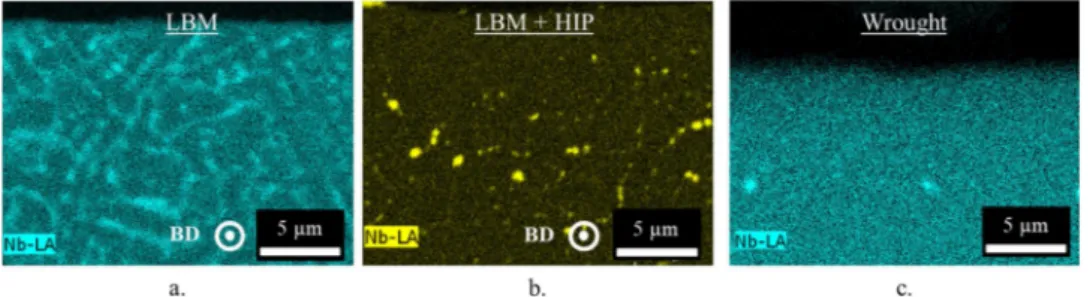
Both the as built LBM and the as built LBM + HIP systems have a high surface roughness which is due to two phenomena resulting from the LBM process. The first surface roughness type is fairly regular,
Fig. 2a, and corresponds to the layers of powder deposited one over another. The wavelength of this surface roughness is approximately 175 μm,Fig. 2b. The second type is due to the high energy density used in the additive manufacturing process. When the laser is on the edges of the sample, its energy is high enough to partially melt powder-bed grains. These grains therefore adhere on the surfaces parallel to the building direction. The wavelength of this surface roughness is much smaller than the first one,Fig. 2b. The standard deviation of the height distribution, Sq, defined on the sampling surface and calculated using Eq.(5)is equal to 11 +/− 1 μm. = Sq A Z x y dxdy 1 ( , ) A 2 (5) The spot used for the analysis is of 4 mm2and the analysis was done
three times per sample.
From these analyses, it is clear that the developed surface area is
1The gas flow was calculated at 610 °C and at 16 bar from the massic flow rates at 15 °C and 1 bar using the ideal gas law.
using SiC abrasive paper (600 grit) for at least 13 500 h at 570 °C in a gas mixture composed of H2, CO, CO2, CH4 and H2O (aC = 32) [8]. No
work has studied the influence o f t he m anufacturing p rocess o n the metal dusting resistance of this alloy. However, Hong et al. studied the oxidation of TiC/In625 composites obtained by laser metal deposition and subsequently ground [9]. The oxidation followed a parabolic law but the kp was higher than for conventionally made systems. The nature
of the oxide scale remained unchanged and was only composed of chromia. Jia and Gu studied the oxidation of additive manufactured Inconel 718, ground using SiC abrasive paper (1 000 grit) during 100 h at 850 °C under air [10]. The oxidation kinetics was also parabolic and an increase in the energy density decreased the parabolic constant. It therefore seems that the additive manufactured parameters have an influence on the oxidation of the obtained part. Sanviemvongsak et al. obtained lower parabolic constants for the oxidation of Inconel 718, raw and ground (600 grit) at 850 °C under air [11]. They also showed that the difference i n t he o xidation k inetics b etween t he additive manufactured and wrought parts only came from the difference in the surface roughness.
higher than the projected surface area. The developed surface area over projected surface area ratio (Sdr parameter: ISO 25178: developed in-terfacial ratio) was first determined using a confocal microscope. It was also calculated by cutting the sample along the building direction and measuring the length of the developed surface. In both cases, this ratio was of 1.5 +/− 1 for both the LBM and LBM + HIP systems. Sanviemvongsak et al. [11] showed for 718 alloy fabricated by SLM and EBM, that oxidation kinetics were proportional to the developed surface area, provided that the thickness of the oxide scale was smaller than the height of the peaks or valleys. However, metal dusting mass variation includes pits and localised carburisation in addition to homogeneous oxidation. Therefore, it was decided to show the mass variations di-vided by the area of the projected surface, and not didi-vided by the de-veloped surface area.
XRD analyses, Fig. 3, show no difference between the LBM, LBM + HIP and Wrought systems before exposure to the metal dusting atmosphere. Indeed, only the γ matrix was detected.
Raman characterization and SEM observations with EDX analyses,
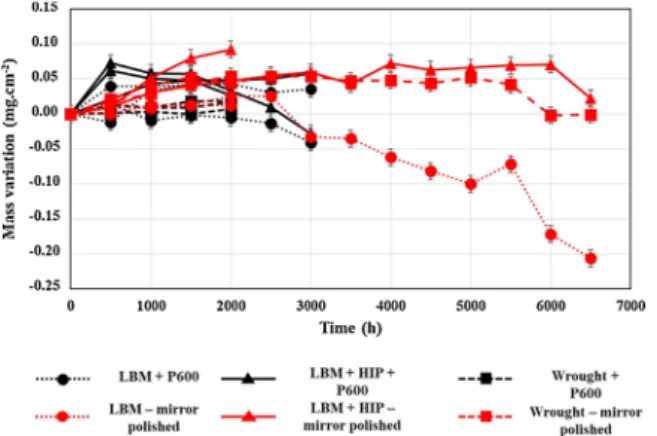
Fig. 4, show the local presence of alumina on the surface of both the LBM and the LBM + HIP systems. However, no protective continuous alumina or chromia scale is present on the surface.
The EDX maps of the cross section of the LBM system,Fig. 5a, show that Nb segregates in the interdendritic regions. Thivillon et al. reported Nb segregation for cast or welded In625 [12], which does not appear for the wrought samples studied in this work,Fig. 5c. Xu et al. con-sidered Nb to be in the form of a Lave phase (Ni,Cr,Fe)2(Nb,Mo,Ti)
[13]. This brittle intermetallic compound is detrimental for the tensile,
fatigue and creep properties and its presence depends on the additive manufacturing scanning parameters used [12,13]. In the present work, the presence of a Lave phase in such a large volume fraction would have been detected by XRD but it was not. However, the matrix pics of the LBM system are wider than that of the LBM + HIP system. It is possible that these wide matrix pics are due to the presence of a Nb-rich matrix in addition to the less Nb-rich matrix. After the HIP treatment, this segregation disappears, replaced by the formation of a Nb-rich phase at the grain boundaries. After the additive manufacturing process, the system is not at the thermodynamic equilibrium. Indeed, the high
Fig. 1. Summary of the studied samples.
Fig. 2. (a) Surface roughness, (b) profile and (c) optical micrograph of the surface of the LBM system after fabrication.
cooling rate traps the Nb in the interdendritic regions and does not allow the stable phases to form. However, after 3 h at 1160 °C, the system evolves towards the equilibrium. Thermo-Calc calculations carried out using TCNi7 database show that 10 vol% of the δ-Ni3Nb
phase should be formed at thermodynamic equilibrium.
Fig. 6shows EBSD-KAM (Kernel average misorientation) maps of the LBM, LBM + HIP (both not ground and cut perpendicular to the building direction) and of the Wrought + P600 systems. KAM measures the local misorientation between a pixel and its neighbours and therefore indicates the level of internal strain or dislocation density. The caption inFig. 6d links a KAM number to a colour in the adjoining maps. In the case of the LBM system, the microstructure is very in-homogeneous. Small grains of approximately 10 μm in diameter are detected near the surface. The core-microstructure is constituted of layers of larger grains of about 15 μm wide and 70–80 μm long sepa-rated by layers of smaller equiaxed grains. In between both micro-structures, there seems to be much larger grains, not easily defined in terms of dimension and shape. The distance between the layers of equiaxed grains is approximately of 100 μm, which matches the laser diameter. The small grains can therefore be the result of multiple meltings due to the laser overlap when scanning. The KAM maps also show that strain is particularly important in this region, which is con-sistent with the hypothesis of multiple meltings and therefore increased thermal stresses. Kuo et al. also observed higher dislocation density in the laser overlap regions for Inconel 718 obtained by selective laser melting [15].
In the case of the LBM + HIP system, the fine microstructure near the surface of the LBM is no longer observed. Large heterogeneous grains and numerous twins formed at the surface and in the core of the alloy. As already mentioned, the HIP treatment consists of a pressured heat treatment at 1160 °C during 3 h under 1020 bar of Ar. Kuo et al. and other studies showed that at temperatures above 1050 °C re-crystallization occurs when sufficient dislocation density is present [14–16]. The dislocations needed to recrystallize the alloy are indeed present before the HIP treatment, as shown in the KAM maps of the LBM system (Fig. 6). However, the high density of dislocations in the laser overlap regions creates an uneven distribution of dislocations. This causes a heterogeneous recrystallization, which explains the het-erogeneous grain size of the LBM + HIP samples. After HIP, no
deformation within the grains was observed. The heat treatment eliminated all the dislocations by recrystallizing the alloy. The wrought alloy presents an uneven distribution of grains, ranging from 1 to 60 μm in diameter, with 75 % of the grains under 20 μm. The grains are therefore smaller in the case of the Wrought alloy.
The number of grain boundaries or twins encountered when drawing a line parallel to the surface at different depths is reported
Table 1. This analysis shows that among the additive manufactured systems, the LBM microstructure exhibits smaller grains, especially near the surface where the amount of grain boundaries (including twins) is four times higher than in depth. The diffusion through the grain boundaries in the case of the LBM system could therefore be enhanced compared to the LBM + HIP system.
The grain orientation along the building direction is shownFig. 7. The LBM pole figures show that the microstructure is textured with the {100} directions parallel to the axis (X, Y, Z). However, after the HIP treatment, the LBM strong texture disappears. Preferential orientations still exist but it should be noted that the minimum of the MUD (multiple of uniform distribution that corresponds to the fraction of grains which has a particular crystallographic orientation reported on the pole fig-ures) is much lower for the LBM (0.01) than for the LBM + HIP (0.1) system. The preferred orientations in the case of the LBM + HIP system are therefore less important than for the LBM system.
In addition to as built samples, both ground and polished LBM and LBM + HIP were studied in this work. Grinding and polishing drasti-cally decreased the large surface roughness, resulting from LBM, from 11 +/- 1 μm down to 0.110 μm and 0.015 μm, respectively [17]. Ap-proximately 200 μm were removed from each side. In the case of the LBM system, the fine surface microstructure observed on the non-ground samples was therefore removed by grinding. The surface mi-crostructure of the ground and polished samples corresponds to the layers of larger grains of about 15 μm wide and 70–80 μm long sepa-rated by layers of smaller equiaxed grains. In the case of the LBM + HIP system, the oxide scale is therefore no longer present after grinding and polishing. However, the Nb segregation as well as the microstructure observed for the non-ground samples are still valid for the ground and polished samples.
Fig. 4. SEM observations of the (a) LBM and (b) LBM + HIP systems after fabrication.
3.2. Effect of the manufacturing process and of the surface preparation
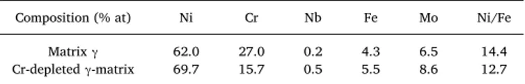
In this section, the ground and polished LBM and LBM + HIP samples exposed to the metal dusting atmosphere are studied. The mass variations of the six systems are presentedFig. 8. Error bars are cal-culated taking into account the incertitude of the balance, of the measuring calliper and the mean of the three weighings for each sample. First, it can be noticed that the mass variations are very small for all samples. For the sake of comparison, note that the growth of a one micrometer thick chromia scale would correspond to a mass gain of 0.164 mg/cm². The Wrought + P600 system has the lowest mass gain and exhibits the most reproducible behaviour. LBM + P600 and LBM + HIP + P600 systems also present low mass gains. As for the mirror polished systems, the mass variations are in the same order of magni-tude as the ground systems.
The behaviour of all samples for a given system is quite similar up to 3 000 h (1 sample of each system was withdrawn from the rig at 2 000 h of exposure). At this time, one sample of each ground system presents mass gain while the other presents a mass loss. This indicates a lack of reproducibility for the LBM + P600 and LBM + HIP + P60 systems. This heterogeneous behaviour is also observed for the LBM-mirror po-lished, as the mass gain measured at 2 000 h, for one of the samples, is twice as much as the mass variation of the other. The variability ob-served for the additive manufactured, ground and polished samples, despite removal of the inhomogeneities of the surface roughness and of the near-surface microstructure with grinding, indicates that the dif-ference in the core-microstructure can be responsible for these
inhomogeneities in terms of mass gain. However, the mass variation is extremely small in all cases, which makes interpretation difficult.
No carburisation was observed at 2 000 h on the analysed samples for each system. No pit was observed macroscopically on any surface either. This lack of metal dusting degradation for the six systems is due to the formation of a continuous chromia scale on the surface (Fig. 9). This oxide does not catalyse the decomposition of the carbon-rich molecules [18], thus preventing carbon adsorption on the surface. However, differences can be observed in the oxide scales. The chromia scale formed on the surface of the ground systems, after 2 000 h of exposure, is homogeneous in thickness (LBM + P600: 174 +/− 40 nm, LBM + HIP + P600: 167+/− 20 nm and Wrought + P600: 201 +/− 30 nm) whereas the polished systems exhibit a more heterogeneous chromia scale. This is particularly the case for the LBM-mirror polished on which a continuous but not dense chromia scale and intergranular alumina are observed. Nb segregation under the chromia scale is also observed in all cases. The Cr depletion due to the formation of the chromia layer decreased the Cr chemical potential. Chyrkin et al. showed that the Cr and Nb chemical potentials are linked, the Cr de-pletion layer is therefore a zone where the Nb potential is decreased [19]. Nb diffuses to the surface forming δ-Ni3Nb phase (detected by
XRD analyses, not shown here). This δ-Ni3Nb layer is less present in the
case of the polished samples. This is consistent with the fact that the grinding brought dislocations to the sub-surface area which play the role of fast diffusion paths. It is well known that such grinding favours Cr diffusion and helps the formation of the protective chromia scale [20]. The same effect can be expected with Nb, grinding enhancing Nb
Fig. 6. EBSD – KAM maps of the (a.1) and (a.2) LBM, (b.1) and (b.2) LBM + HIP and (c) Wrought systems at the surface and core before exposure to metal dusting
atmosphere. (d) Local misorientation scale.
Table 1
Number of grain boundaries (GB) and twins, per mm, perpendicular to the surface at different depths.
Per mm LBM LBM + HIP Wrought
GB Twin GB Twin GB Twin
At the surface 183 0 21 +/− 1 27 +/− 1 The wrought alloy is considered identical in terms of grain size, throughout the sample Total: 183 Total: 49
100 μm deep 54 0 18 22 +/− 1 Total: 54 Total: 40 +/−1
600 μm deep 63 0 12 20 +/− 5 141
diffusion towards the surface. When comparing the ground wrought and additive manufactured systems, it was observed that the first one had less Nb under the chromia scale. This could be due to the fact that less Nb is present in the alloy obtained by LBM, therefore forming less δ-Ni3Nb. In order to better understand the influence of grinding and of
the microstructure on the presence of the Ni3Nb layer, the Cr diffusion
profiles should be studied. However, the thin oxide scales induce very short diffusion profiles (around 1 μm deep) making their analyses using SEM-EDX impossible.
Despite initial microstructural differences between the six systems, all of them were able to form a protective oxide scale on their surface. Up to 3 000 h, no metal dusting degradation was observed on any of the studied systems. The manufacturing process does not seem to have an
influence on the metal dusting resistance of the core material for the tested duration. However, Fabas et al. reported that wrought In625 does not show any sign of metal dusting degradation after 13 500 h at 570 °C, with a carbon activity of 32, an oxygen partial pressure of 7.1 × 10⁻²⁶ bar and under 21 bars of pressure [8]. It is therefore
possible that any differences between the manufacturing processes will only appear after a longer exposure time. The inhomogeneous chromia scale formed on the LBM-mirror polished samples might induce poor metal dusting resistance after longer testing time. Indeed, even if no pit has been detected, the mass variation of the LBM-mirror polished samples decreases after 2 500 h.
3.3. Influence of the chemical composition beneath the oxide scale
EDX analyses were performed under the chromia scale on the pre-viously analysed samples. Cr-depletion was observed. When Cr diffuses towards the surface, a Ni and Fe concentration gradient forms in the opposite way. Ni and Fe therefore diffuse towards the core of the sample. Fe diffuses faster than Ni in Ni-Fe-Cr alloys [21], explaining the increase of the Ni/Fe ratio. The carburation could therefore be different than in the regular matrix. Moreover, Strauss and Grabke showed that the presence of Nb increased the incubation time by forming Nb-car-bides instead of Cr23C6, leaving the Cr free to form chromia [22]. Even
though, no carburisation or metal dusting degradation has yet been observed on either the ground or the polished samples, it is interesting to study the possible influence of the Cr-depleted layer and of the δ-Ni3Nb layer. Thermo-Calc calculations were performed to compare the
carburisation of the regular matrix with the Cr-depleted matrix. How-ever, thermodynamic calculations are not possible to evaluate the carburisation behaviour of the δ phase, as this phase is not described with carbon in the TCNI7 database. The carburisation of this phase is therefore studied using data from the literature. Equilibrium
Fig. 7. Pole figures of the (a) LBM, (b) LBM + HIP and (c) Wrought systems with the Z direction parallel to the building direction before exposure to the metal
dusting atmosphere.
Fig. 8. Mass variation of the ground P600 and mirror polished LBM,
LBM + HIP and Wrought systems during exposure to metal dusting atmo-sphere.
calculations (with TCNI7 database) using the chemical compositions obtained by EDX measurements in the Cr-depleted layer and at the core of the sample were performed. These calculations gave two stable phases (for both compositions): mostly γ and some δ. The composition given by Thermo-Calc for the γ phase is the one used in the following Thermo-Calc calculations to study the carburisation of the Cr-depleted and regular γ matrixTable 2.
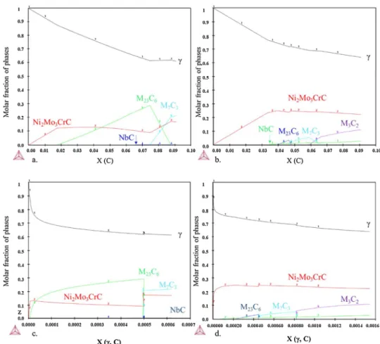
Fig. 10presents the mole fraction of each phase after the addition of carbon in the matrix (Cr-depleted or not). The carbon activity remains under 1 whichever the carbon content studied here. Fig. 10a and b show that the amount of carbides formed is not the same according to the matrix. The first carbide to form, in both cases, is the M6C carbide
(eta-carbide, phase prototype: W3Fe3C). Its composition, as given by
Thermo-Calc, is close to Ni2Mo3CrC. However, the final molar fraction
is larger in the case of the Cr-depleted γ matrix. This is due to the larger amount of Ni and Fe in this matrix. However, the molar fractions of the Cr carbides (Cr7C3and Cr23C6) are systematically inferior in the case of
the Cr-depleted matrix.Fig. 10c and d show the carbon molar fraction in γ at which the carbides form. It shows that the carbon solubility in the Cr-depleted γ matrix is lower than in the regular matrix. This should reduce the carbon permeability in the case of the Cr-depleted γ matrix and therefore the carburisation of the alloy. The solubility of carbon in the δ-Ni3Nb phase cannot be calculated via Thermo-Calc but
Con-netable et al. showed using DFT calculations that the carbon solubility energy in δ is higher than in γ [23]. The solubility of carbon in δ should therefore be lower than in γ. It is then possible that the presence of a continuous δ layer could play a similar role as the chromia layer, acting as a diffusion barrier for carbon, limiting the carburisation of the alloy and therefore the disintegration of the surface by metal dusting. How-ever, the presence of δ precipitates in the γ matrix could also modify the carburisation of the alloy. Indeed, when Nb carbides are formed, the δ phase dissolves to release Nb in the γ matrix. The δ phase acts as a reservoir of Nb and allows a large quantity of Nb carbides to form. The upward diffusion of Nb which causes the precipitation of δ in γ could then be detrimental for the alloy. However, the presence of δ in the Cr-depleted matrix could favour the formation of Nb-carbides (more Nb available), trapping the carbon and therefore leaving more Cr free to form chromia.
The chemical composition under the oxide scale modifies the car-burisation of the alloy and therefore the volume expansion resulting
from carbide formation. The volume expansion coefficient of each carbide with respect to γ-Ni and δ-Ni3Nb was calculated by dividing the
volume of one carbide unit cell by the volume of γ or δ needed to form one carbide unit cell. The cell parameters were taken from the inorganic crystal structure database (ICSD). According to Thermo-Calc, the M6C
carbides formed present the following chemical composition: Ni2Mo3CrC. This carbide does not match any crystals in the ICSD
da-tabase, therefore the Ni3Mo3C parameters (present in the database)
were used to calculate the volume expansion coefficient of this carbide. The coefficients are reported inTable 3. The volume expansion coef-ficients of each carbide compared to the Cr-depleted γ-matrix are considered equal to those compared to the regular γ-matrix because of the similar lattice parameters between both γ matrices.
From these coefficients the global volume expansion in γ and in the Cr-depleted γ, due to the formation of carbides, is calculated. It is plotted inFig. 11.Fig. 11shows that the global volume expansion is higher in the Cr-depleted γ matrix. This is due to the fact that the vo-lume fraction of Ni2Mo3CrC is higher in the Cr-depleted γ matrix and
that the volume expansion coefficient of this carbide is slightly higher than those of Cr7C3and Cr23C6. The carburisation of the Cr-depleted γ
matrix could cause more internal stresses and favour the disintegration of the surface.
The volume expansion coefficients compared to δ-Ni3Nb were also
calculated. Indeed, when a δ-Ni3Nb precipitate is present in the γ matrix
(Cr-depleted or not), elements (mainly Nb) contained in δ diffuse to γ and form carbides. The volume change is therefore from a Nb in δ to a Nb in a carbide. The presence of δ precipitates in the γ matrix favours the formation of NbC. The volume expansion coefficient of this carbide is higher than any other carbide studied here. The global volume ex-pansion of the alloy could therefore be higher, depending on the amount of carbides formed. The presence of these precipitates under the oxide scale could therefore be detrimental to the alloy in terms of volume expansion.
3.4. Influence of the surface roughness and of the HIP treatment 3.4.1. Mass variations
Fig. 12 compares the mass variations between ground and raw samples. Error bars are not visible here as they are very small compared to the mass variations. It is quite clear that not grinding the surface increases the mass variations and promotes a heterogeneous behaviour among the samples of a same system. However, while the total mass loss for each raw LBM sample is different, the global behaviour is the same. A large mass loss is observed up to 2 000 h. At this point, no more mass change occurs until 5 500 h. On the contrary, the three raw LBM + HIP samples do not show similar behaviour.
The incubation time seems to be similar for both systems (observed
Fig. 9. SEM cross sections of the six studied systems after 2 000 h of exposure to metal dusting (BSE mode). Table 2
Chemical compositions used for Thermo-Calc calculations.
Composition (% at) Ni Cr Nb Fe Mo Ni/Fe Matrix γ 62.0 27.0 0.2 4.3 6.5 14.4 Cr-depleted γ-matrix 69.7 15.7 0.5 5.5 8.6 12.7
on only one sample for each system because the others were withdrawn at shorter exposure times): around 5 500 and 6 000 h. However, an-other LBM + HIP sample presents pits after only 3 000 h, showing again the non-reproducibility of the system behaviour.
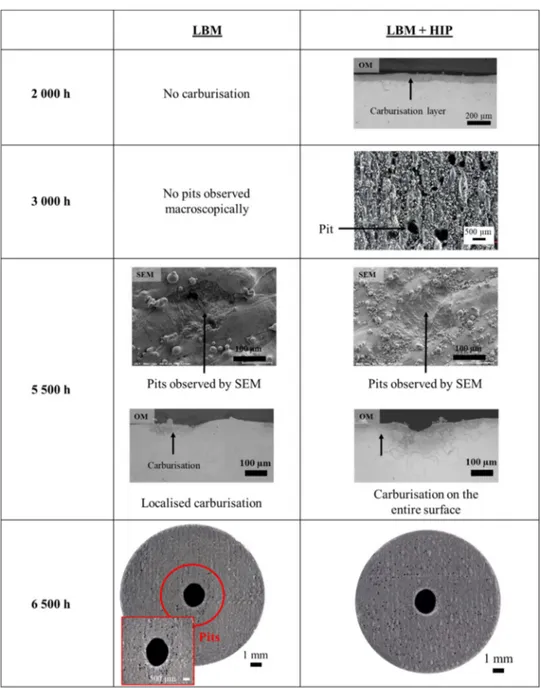
3.4.2. Characterisation of the carburised zone
No metal dusting degradation (carburisation zone or pits) was ob-served using an optical microscope for the LBM system until 5 500 h. At this stage, carburisation zones and pits were observed thanks to optical and electronic microscopy observations respectively,Fig. 13. The pits observed have a diameter of about 100−200 μm. Localised carburisa-tion was also revealed on this system by Murakami’s chemical attack after 5 500 h. On the other hand, signs of metal dusting degradation appear earlier for the LBM + HIP system. A homogeneous carburisation layer is already observed after 2 000 h of exposure and pits are observed macroscopically after 3 000 h for one of the samples and after 5 500 h for another, confirming the heterogeneous behaviour of the LBM + HIP system. At 6 500 h it is clear that the most corroded system is the LBM + HIP one.
SEM observations show that after 2 000 h, a non-continuous chromia layer was present on the surface of the raw LBM sample while the raw LBM + HIP system presents a continuous layer of chromia on the surface. This is not consistent with the 70 μm deep carburisation
observed for the raw LBM + HIP system after 2 000 h,Fig. 13. Indeed, a chromia layer should protect the alloy from any metal dusting de-gradation while the absence of a continuous protective layer on the surface of the LBM sample should favour metal dusting attack. The homogeneous thickness of the carburisation layer, at 2 000 h for the
Fig. 10. Thermo-Calc calculations using TCNI7 database, molar fraction of phases according to the global carbon concentration in (a) the regular γ matrix and (b) the
Cr-depleted γ matrix. Molar fraction of phases according to the amount of carbon in the γ phase in (c) the regular and (d) the Cr-depleted matrix.
Table 3
Volume expansion coefficients to form a carbide from the Cr, Mo or Nb belonging to the matrix γ or to the phase δ.
Carbides NbC CrC MoC Cr7C3 Cr23C6 Cr3C2 Ni3Mo3C
Volume expansion coefficient compared to γ 1.90 1.39 1.67 1.18 1.13 1.28 1.21 Volume expansion coefficient compared to δ 1.82 1.33 1.60 1.13 1.08 1.22 1.15
Fig. 11. Volume expansion within γ and Cr-depleted γ due to the formation of
Fig. 12. Mass variation of raw and ground LBM (left side) and LBM + HIP (right side) systems.
LBM + HIP sample, indicates that this phenomenon is not localised at some defects of the oxide scale. As no initial protective oxide scale was present before exposure to metal dusting, Fig. 4, this carbon intake probably occurred before the formation of a continuous and protective chromia scale. In the early stages of metal dusting exposure, there is competition between the oxidation of the alloy and its carburisation [24,25]. If the decomposition of the carbon-rich molecule and the dif-fusion of carbon in the alloy is faster than the formation of the chromia scale, a carburisation layer can form.
By using Wagner’s simplified diffusion model (the carbon is here considered to be the only diffusing atom), the expected depth (X) of the intragranular carburisation layer was calculated using Eq. 6.
X2= 2 k
pt (6)
With t the duration of the diffusion in seconds and kpthe parabolic
constant expressed according to Eq. 7:
=D N k N C Cs p ( ) Cr (7)
In this case, Dcis the carbon diffusion coefficient in γ - Ni, NC(s)the
surface concentration of carbon, ν the ratio of carbon on metal in the
carbide and NCrthe original concentration of Cr in the alloy. The
sur-face concentration of carbon is considered to be the concentration for which the first carbide forms and is calculated using Thermo-Calc (TCNI7 database). If the carbides formed (revealed by chemical etching) are considered to be Cr7C3, the calculated carburisation depth
is of 37 μm which is lower than the 70 μm deep carburisation observed. However, TEM analyses of the oxide scale after 2 000 h of exposure showed the presence of FeCr2O4spinel oxide within the chromia scale
(identified by electron diffraction). The presence of a non-protective oxide also explains the carburisation of the LBM + HIP system.
As previously shown inFig. 13, after 5 500 h, both systems present some carburisation. In the case of the LBM system it was localised whereas the LBM + HIP system exhibited localised intragranular car-burisation and general intergranular carcar-burisation,Fig. 14a. The gen-eral intergranular carburisation of the LBM + HIP sample could be explained by the initial competition between oxidation and carburisa-tion. However, the localised carburisation and the presence of pits on both systems are results of a localised metal dusting attack.Fig. 14a shows that intragranular carburisation only occurs when intergranular carburisation occurred. It is therefore probable that carbon diffuses along the grain boundaries and forms intergranular carbides. When the grain boundary is saturated, carbon diffuses into the grain and forms
Fig. 14. (a) OM (top) and SEM (bottom) images of cross-section of Murakami's chemical attack of the LBM (left side) and LBM + HIP (right side) systems, (b)
STEM-EELS profile (left side) of carbides (in the grain and at the grain boundary) and a HAADF (high-angle annular dark-field) image of analysed zone (right side) after 5 500 h in the metal dusting atmosphere.
intragranular carbides. STEM-EELS analysis were carried out to de-termine the nature of the carbides, Fig. 14b. Concentration profiles show large quantities of chromium in carbides, Fig. 14b. Chromium carbides are therefore present inside the grains and at the grain boundaries. This is consistent with the fact that intra and intergranular carburisation was observed optically after Murakami’s chemical etching.
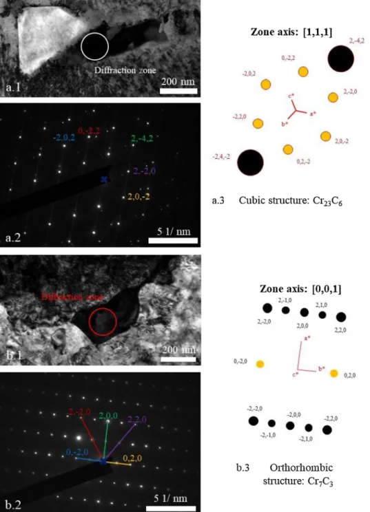
Electron diffraction patterns (SAED in the TEM) showed that both Cr23C6and Cr7C3carbides formed (Fig. 15). The cubic structure of the
Cr23C6 matches the calculated electron diffraction pattern obtained
(Fig. 15a.1.2.3). As for the second electron diffraction pattern, the or-thorhombic structure matches with the calculated electron diffraction
pattern obtained (Fig. 15b.1.2.3) but there are supplementary spots placed at mid distance between two spots of carbide structure. This can indicate that there is a substitution of a Cr or C atom every 2 cells. The atomic chemical composition of this carbide (C - 38 %, Cr - 57 %, Ni - 5 %, Mo - 5 %) favours this hypothesis. It is indeed possible that a Cr atom is replaced by a Ni or Mo atom.
3.4.3. Metal dusting degradation of the LBM and LBM + HIP systems
In order to better understand the degradation mechanisms, TEM analyses coupled with EDX were carried out at the edge and in the middle of a pit for the raw LBM and LBM + HIP systems. The different phases mentioned were all, except if specified, identified by
Fig. 15. (a.1, b.1) Bright Field (BF) TEM images and (a.2, b.2) related experimental and (a.3, b.3) calculated SAED patterns of carbides on the LBM + HIP system
after 5 500 h of exposure to metal dusting. Crystallographic data used for calculation are from Li and Tang [26] and Yakel [27]. The reconstruction was performed with CaRIne software [28].
quantitative EDX and electron diffraction analyses.
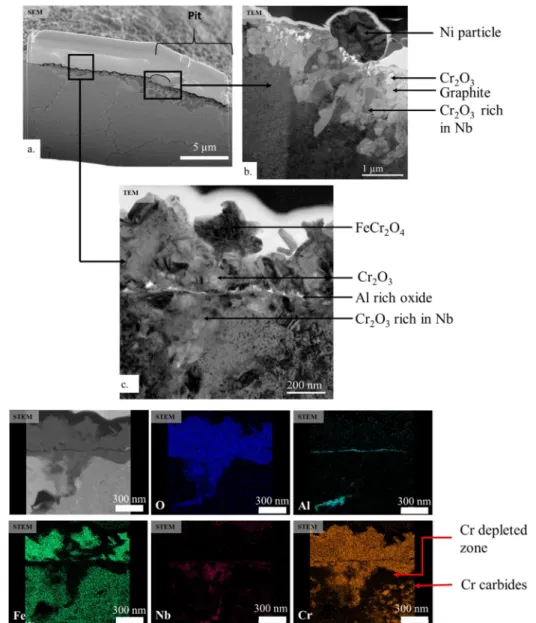
Fig. 16a shows the FIB cross-section taken at the border of a pit on the LBM system exposed 5 500 h to the corrosive atmosphere.Fig. 16b and c are close ups of 16.a obtained after thinning the FIB lamella. HAADF image and STEM-EDX maps of c are shown inFig. 16d. The oxide scale around the pit, on the LBM system, is composed of various oxides,Fig. 16a, c, d. The first layer is a mix of chromia and a spinel oxide, FeCr2O4. Underneath, according to EDX analysis, it is possible
that an alumina layer has formed. However, this oxide could not be identified by electronic diffraction. The third layer, close to the alloy is a mix of chromia and a niobium-rich chromia.
The presence of a spinel oxide explains the metal dusting attack. Spinel oxide favours metal dusting as it enables carbon-molecules to decompose [5]. Moreover, carbon diffusion is faster through this oxide than through chromia or alumina [29]. A metal dusting mechanism can therefore occur.
A nickel metallic particle marks the border between the pit and the oxide scale,Fig. 16b. The subsurface morphology changes at the border of the pit,Fig. 16b. An alternating morphology with graphitic carbon and chromia has formed. In the middle of the pit, the morphology is different,Fig. 17. The top layer is graphitic carbon. However, under-neath, a continuous layer of chromia is on top of the alloy. Ni metallic
particles are at the interface between the graphite and the chromia layer. It is possible that these metallic particles catalyse the decom-position of the carbon-rich molecules and the formation of graphite. Moreover, δ-Ni3Nb phases are present within the matrix close to the
oxide scale and carbides form under the Cr-depleted zone.
In the case of the LBM + HIP system, the oxide near the pit (not shown here) is also composed of a mix of chromia and FeCr2O4.
Particles of alumina are present underneath this mixed scale. However, contrary to the LBM system, the centre of the pit is not composed of a layered structure but of an intricate mix of chromia, graphite and Ni and Nb particles,Fig. 18. The Ni metallic particles embedded within this structure probably catalyse the formation of graphite. In the matrix Cr carbides are observed inside the grains and at the grain boundaries directly under the oxide scale.
Mechanisms that can be proposed for the metal dusting degradation of the LBM and the LBM + HIP systems are fairly similar and shown
Figs. 19 and 20respectively. The TEM analyses showed that both sys-tems formed a mix of chromia and spinel oxide layer. The waviness of the surface might enhance the formation of the spinel oxide. Cr dif-fusing towards the surface will take the shortest path to follow the highest concentration gradient. For example, if the Cr diffuses towards the surface under a peak, it will not diffuse to the top of the peak but to
Fig. 16. (a) SEM image of FIB lamella of the raw LBM system at the border of a pit after 5 500 h of exposure to metal dusting. (b) and (c) BF TEM images of the surface
Fig. 17. BF TEM image (left side) and STEM-HAADF image (right side) of the bottom of the pit of the raw LBM system after exposure for 5 500 h to the metal dusting
atmosphere.
Fig. 18. BF-TEM (top central) and HAADF (top left) images and related STEM-EDX analysis of the LBM + HIP system after 5 500 h of exposure to the metal dusting
the closest surface,Fig. 19a. This forms a Cr depleted zone below the surface, enhancing the formation of a spinel oxide in detriment to chromia. This unprotective oxide catalyses the decomposition of the carbonated molecules (b) and carbon diffuses along the grain boundary to form inter (c) and intragranular carbides (d). The formation of car-bides and of graphite in epitaxy with (111) planes of Ni creates internal stresses causing the disintegration of the surface and the formation of a pit (e). The bare alloy reoxidises forming a chromia scale within the pit (f). However, as Ni does not oxidise at this low oxygen partial pressure, Ni-particles form within or at the surface of the chromia scale. These particles catalyse the formation of the graphite layer on top (g). The same corrosion products form for the LBM + HIP system. Nevertheless, their structure is different, close to the corrosion products observed in Albertsen’s study where the oxidation of the carbides results in alter-nating layers of chromia, alumina, graphite and Ni + Fe [30]. In our case, the reason for this particular structure of corrosion products is not understood yet. However, this shows the importance of oxidation in the metal dusting process. Other studies by Szakalos et al. also pointed out that role [31,32]. However, the absence of a carbide free zone on the LBM + HIP system is probably due to the thinner oxide scale (374 nm +/− 142 nm for the LBM + HIP system compared to 526 nm +/− 149 nm for the LBM system). Indeed this thinner oxide scale induces a less Cr-depleted layer underneath: according to EDX, the amount of Cr under the oxide scale for the LBM + HIP system is equal to 20 +/− 2 %at whereas it is equal to 8.5 +/− 0.5 %at for the LBM system. The amount of Cr directly under the oxide scale for the LBM system is therefore not sufficient to form Cr-carbides.
Even though the mechanisms for the metal dusting degradation of both systems are fairly similar, the amount of pits on the LBM + HIP
samples is much more important than on the LBM samples. The mi-crostructure with large grains, observed for the LBM + HIP system,
Table 1, slows down the diffusion kinetics of Cr towards the surface, enhancing the formation of spinel oxide, favouring pits formation.
4. Conclusions
The resistance to metal dusting of the In625 produced by SLM was characterised during thousands of hours in a 48%H2-9%CO-6%CO2
-3%CH4-34%H2O atmosphere at 610 °C, with aC= 6.9 and
PO2= 1.8 × 10⁻²⁴bar. The influence of the manufacturing process,
sur-face roughness and HIP was studied and several conclusions can be drawn: - When the surface roughness is decreased by grinding the surface of the samples, the manufacturing process does not influence the metal dusting resistance up to 6 500 h of exposure. This demonstrates the good quality of LBM samples.
- Ground samples form a more homogeneous and protective oxide scale than polished samples. This may be due to a higher dislocation density below the surface due to grinding, dislocations acting as diffusion short circuits for upward Cr diffusion [19].
- Thermo-Calc calculations show that a Cr-depleted matrix reduces the carbon solubility and therefore could reduce the carbon inward flux into the alloy. However, the volume fraction of carbides is higher which causes larger volume expansion and therefore more internal stresses.
- Non ground LBM and LBM + HIP samples show higher mass var-iations than ground samples, and the hipped samples show a non-reproducible behaviour.
- The waviness of the raw samples, due to the additive manufacturing process, enhances the formation of a spinel oxide that allows inward carbon diffusion and favours metal dusting degradation. The surface roughness has therefore a strong influence on the metal dusting degradation.
- The large grain size of the LBM + HIP samples due to the HIP treatment slows down the diffusion of chromium towards the sur-face and favours the formation of Fe-containing spinel oxide. The LBM + HIP system is therefore the most corroded system.
CRediT authorship contribution statement
A. Vernouillet: Conceptualization, Validation, Investigation,
Writing - original draft, Visualization. A. Vande Put: Conceptualization, Validation, Resources, Writing - review & editing, Visualization, Supervision, Project administration, Funding acquisition.
A. Pugliara: Validation, Investigation, Writing - review & editing. S. Doublet: Validation, Resources, Writing - review & editing,
Supervision, Funding acquisition. D. Monceau: Conceptualization, Validation, Resources, Writing - review & editing, Supervision, Project administration, Funding acquisition.
Declaration of Competing Interest
The authors declare that they have no known competing financial interests or personal relationships that could have appeared to influ-ence the work reported in this paper.
Data availability
The raw/processed data required to reproduce these findings cannot be shared at this time as the data also forms part of an ongoing study.
Data availability
The raw/processed data required to reproduce these findings cannot be shared at this time as the data also forms part of an ongoing study.
Acknowledgments
Authors would like to thank BPI France for financial support of the FAIR project and Air Liquide for helpful discussions and technical support. The authors would also like to thank Arnaud Proietti for EBSD observation, Claudie Josse for FIB sample preparation and Teresa Hungria for STEM-EELS observations (Centre de Microcaractérisation Raimond Castaing).
References
[1] D.J. Young, J. Zhang, C. Geers, M. Schütze, Recent advances in understanding metal dusting: a review, Mater. Corros. 62 (2011) 7–28,https://doi.org/10.1002/maco. 201005675.
[2] A. Aguero, M. Gutiérrez, L. Korcakova, T.T.M. Nguyen, B. Hinnemann, S. Saadi, Metal dusting protective coating. A literature review, Oxid. Met. 76 (2011) 23–42,
https://doi.org/10.1007/s11085-011-9248-4.
[3] H. Taheri, M.R.M. Shoaib, L.W. Koester, T.A. Bigelow, P.C. Collins, L.J. Bond, Powder-based additive manufacturing- a review of types of defects, generation mechanisms, detection, property evaluation and metrology, Int. J. Additive and Subtractive Materials Manufacturing 1 (2017) 172–209,https://doi.org/10.1504/ IJASMM.2017.10009247.
[4] W. Sames, F. List, S. Pannala, R. Dehoff, S. Babu, The metallurgy and processing science of metal additive manufacturing, Int. Mater. Rev. 61 (2016) 315–360,
https://doi.org/10.1080/09506608.2015.1116649.
[5] M. Rombouts, G. Maes, M. Mertens, W. Hendrix, Laser matel deposition of Inconel 625 : microstructure and mechanical properties, J. Laser Appl. 24 (2012) 1–6,
https://doi.org/10.2351/1.4757717052007.
[6] S. Li, Q. Wei, Y. Shi, Z. Zhu, Microstructure characteristics of inconel 625 superalloy manufactured by selective laser melting, J. Mater. Sci. Technol. 31 (2015) 946–952,
https://doi.org/10.1016/j.jmst.2014.09.020.
[7] D.J. Young, Metal dusting reaction mechanisms, Mater. Sci. Forum 522-523 (2006) 15–26 https://doi.org/10.4028/www.scientific.net/MSF.522-523.15.
[8] A. Fabas, A. Rouaix-Vande Put, S. Doublet, D. Domergue, M. Salem, D. Monceau, Metal dusting corrosion of austenitic alloys at low and high pressure with the effects of Cr, Al, Nb and Cu, Corros. Sci. 123 (2017) 310–318,https://doi.org/10.1016/j. corsci.2017.04.015.
[9] C. Hong, D. Gu, D. Dai, S. Cao, M. Alkhayat, Qi. Jia, A. Gasser, A. Weisheit, I. Kelbassa, M. Zhong, R. Poprawe, High temperature oxidation performance and its mechanism of TiC/Inconel 625 composites prepared by laser metal deposition ad-ditive manufacturing, J. Laser Appl. 27 (2015) S17005,https://doi.org/10.2351/1. 4898647.
[10] Q. Jia, D. Gu, Selective laser melting additive manufactured Inconel 718 superalloy parts: high temperature oxidation property and its mechanisms, Optics and laser Technologies 62 (2014) 161–171,https://doi.org/10.1016/j.optlastec.2014.03. 008.
[11] T. Sanviemvongsak, D. Monceau, B. Macquaire, High temperature oxidation of IN 718 manufactured by laser beam melting and electron beam melting: effect of surface topography, Corros. Sci. 141 (2018) 127–145,https://doi.org/10.1016/j. corsci.2018.07.005.
[12] L. Thivillon, P. Bertrand, B. Laget, I. Smurov, Potential of direct metal deposition echnology for manufacturing thick functionally graded coatings and parts for re-actors components, J. Nucl. Mater. 385 (2009) 236–241,https://doi.org/10.1016/ j.jnucmat.2008.11.023.
[13] F. Xu, Y. Lv, Y. Liu, B. Xu, P. He, Effect of heat treatment on microstructure and mechanical properties of inconel 625 alloy fabricated by pulsed plasma arc de-position, Phys. Procedia 50 (2013) 48–54,https://doi.org/10.1016/j.phpro.2013. 11.010.
[14] Y.L. Hu, X. Lin, S.Y. Zhang, Y.M. Jiang, X.F. Lu, H.O. Yang, W.D. Huang, Effect of solution heat treatment on the microstructure and mechanical properties of Inconel
[15] Y. Kuo, T. Nagahari, K. Kahehi, The effect of post-processes on the microstructure and creep properties of alloy718 built up by selective laser melting, Materials 11 (2018) 996,https://doi.org/10.3390/ma11060996.
[16] W. Tucho, V. Hansen, Characterization of SLM-fabricated Inconel 718 after solid solution and precipitation hardening heat treatments, J. Mater. Sci. 54 (2018) 823–839,https://doi.org/10.1007/s10853-018-2851-x.
[17] D. Zipperiam, Silicon Abrasive Grinding, PACE Technlogies, 2002. [18] H.J. Grabke, E.M. Muller-Lorenz, Protection of high alloy steels against metal
dusting by oxide scales, Mater. Corros. 49 (1999) 317–320 https://doi.org/ 10.1002/(SICI)1521-4176(199805)49:5 < 317::AID-MACO317 > 3.0.CO;2-5. [19] A. Chyrkin, P. Huczkowski, V. Shemet, L. Singheiser, W. Quadakkers, Sub-Scale
depletion and dnrichment processes during high temperature oxidation of the nickel base alloy 625 in the temperature range 900–1000 °C, Oxid Met 75 (2011) 143–166,https://doi.org/10.1007/s11085-010-9225-3.
[20] D. Monceau, E.M. Muller-Lorenz, H.J. Grabke, Metal dusting of stainless steels, Mater. Sci. Forum 251-254 (1997) 665–670,https://doi.org/10.4028/www. scientific.net/MSF.251-254.665.
[21] S.J. Rothman, L.J. Nowicki, G.E. Murch, Self-diffusion in austenitic Fe-Cr-Ni alloys, J. Phys. F: Metal Phys. 10 (1980) 383–398,https://doi.org/10.1088/0305-4608/ 10/3/009.
[22] S. Strauss, H.J. Grabke, Role of alloying elements in steels on metal dusting, Mater. Corros. 49 (1999) 321–327 https://doi.org/10.1002/(SICI)1521-4176(199805) 49:5 < 321::AID-MACO321 > 3.0.CO;2-P.
[23] F. Connetable, F. Galliano, G. Odemer, C. Blanc, E. Andrieu, DFT study of the so-lubility of hydrogen and carbon in Ni3Nb-D0a and Ni3Nb-D022 systems, J. Alloys. Compd. 610 (2014) 347–351.
[24] H.J. Grabke, E.M. Muller-Lorenz, S. Strauss, E. Pippel, J. Woltersdorf, Effect of grain size, cold-working, and surface finish on the metal dusting resistance of steels, Oxid. Met. 50 (1998) 241–254,https://doi.org/10.1023/A:1018888321213.
[25] S. Strauss, R. Krajak, H.J. Grabke, Coking by metal dusting of nickel-base alloys, Mater. Corros. 50 (1999) 622–627 https://doi.org/10.1002/(SICI)1521-4176(199911)50:11 < 622::AID-MACO622 > 3.0.CO;2-R.
[26] L. Li, J. Tang, Synthesis of Cr7C3 and Cr3C2 by mechanical alloying, J. Alloys. Compd. 209 (1994) L1–L3,https://doi.org/10.1016/0925-8388(94)91060-X. [27] H.L. Yakel, Atom distribution in Tau-carbide phases : Fe and Cr distributions in
(Cr23-XFex)C6 with x=0, 0∙74, 1∙70, 4∙13and 7∙36, Acta Cryst. B43 (1987) 230–238
0108-7681/87/030230-09501.50.
[28] C. Boudias, D. Monceau, CaRIne crystallography 3.1 (c) 1989-2019,http://carine. crystallography.pagesperso-orange.fr.
[29] H.J. Grabke, Metal dusting, Mater. Corros. 54 (2003) 736–746,https://doi.org/10. 1002/maco.200303729.
[30] J.Z. Albertsen, O. Grong, J.C. Walmsley, W. Van Beek, A model for high tempera-ture pitting corrosion in nickel-based alloys involving internal precipitation of carbides, oxides and graphite, Metall. Mater. Trans. 39A (2008) 1258–1276,
https://doi.org/10.1007/s11661-008-9494-5.
[31] P. Szakals, Mechanisms and driving forces of metal dusting, Mater. Corros. 54 (2003) 752–762.
[32] P. Szakalos, S. Hertzman, An active corrosion mechanism for metal dusting on 304L stainless steel, Corros. Sci. 44 (2002) 2253–2270.
625 superalloy fabricated by lasers solid forming, J. Alloys. Compd. 767 (2018) 330–444, https://doi.org/10.1016/j.jallcom.2018.07.087.