O
pen
A
rchive
T
OULOUSE
A
rchive
O
uverte (
OATAO
)
OATAO is an open access repository that collects the work of Toulouse researchers and
makes it freely available over the web where possible.
This is an author-deposited version published in :
http://oatao.univ-toulouse.fr/
Eprints ID : 18522
To link to this article : DOI:10.1177/0954407017690683
URL :
https://doi.org/10.1177/0954407017690683
To cite this version : Venning, James and Lo Jacono, David and
Burton, David and Thompson, Mark C. and Sheridan, John The nature
of the vortical structures in the near wake of the Ahmed body. (2017)
Proceedings of the Institution of Mechanical Engineers, Part D:
Journal of Automobile Engineering, vol. 231 (n° 9). pp. 1239-1244.
ISSN 0954-4070
Any correspondence concerning this service should be sent to the repository
administrator:
staff-oatao@listes-diff.inp-toulouse.fr
The nature of the vortical structures in
the near wake of the Ahmed body
James Venning
1, David Lo Jacono
2, David Burton
3, Mark C Thompson
1and John Sheridan
1Abstract
This study presents the results from high-spatial-resolution water-channel velocity-field measurements behind an Ahmed
body with 25° rear slant angle. The Ahmed body represents a simplified generic model of a hatchback automobile that
has been widely used to study near-wake flow dynamics. The results help clarify the unresolved question of whether the time-mean near-wake flow structure is topologically equivalent to a toroidal vortex or better described by a pair of hori-zontally aligned horseshoe vortices, with their legs pointing downstream. The velocimetry data presented allows the tracking of the vortical structures throughout the near wake through a set of orthogonal planes, as well as the measure-ment of their circulation. The spanwise vortices that form as the flow separates from the top and bottom rear edges are shown to tilt downstream at the sides of the body, while no evidence is found of a time-mean attached toroidal vortex, at least for the Reynolds number (based on the square root of the frontal area) of Re ffiffiffiffiffipFA;30; 000 under consideration.
Keywords
Ahmed body, PIV, vortices
Introduction
The Ahmed body is a widely accepted standardised body used to investigate vehicle aerodynamics.1It has been previously studied in great depth, with particular focus on the effects of the rear slant angle on the wake structures and drag force. In the high drag case (25°, see Figure 1), the time-averaged wake consists of three main three-dimensional structures:
(a) the A vortical structure that is formed by the recir-culation as the flow separates at the top of the ver-tical back surface of the model;
(b) the B vortical structure that is formed due to the separation on the base of the model;
(c) the C-pillar vortices that form as the vorticity in the side boundary layers rolls up over the slant edges.
This paper focusses on the A and B vortices, the nat-ures of which are widely debated in the literature. Some studies refer to these regions as a torus,2–8 similar to the toroidal wake of a cube or square-backed Ahmed model,9,10 although it is now recognised that this torus may only be present when considering a long time-average or a summation of two modes.11,12Others
interpret these structures behind the high drag body as two horseshoe vortices.1,13,14It has even been suggested that the vortex cores form a ‘ring-like vortex’ and that they are two horseshoe vortices with A tilting down-stream and B tilting vertically.15While ample evidence is presented to show that a torus is present behind the time-averaged square-back body,10 there is a limited understanding on how these structures are organized in the high-drag (25°) case.
A particle image velocimetry (PIV) survey of the Ahmed wake presented data showing an increase in streamwise circulation in the C-pillar vortex further downstream than the back of the body.14 Since vorti-city, and hence circulation, cannot be produced
1Fluids Laboratory for Aeronautical and Industrial Research (FLAIR),
Monash University, Australia
2Institut de Me´canique des Fluides de Toulouse (IMFT), Universite´ de
Toulouse, CNRS-INPT-UPS, Toulouse, France
3Department of Mechanical and Aerospace Engineering, Monash
University, Australia Corresponding author:
James Venning, Fluids Laboratory for Aeronautical and Industrial Research (FLAIR), Department of Mechanical and Aerospace Engineering, Monash University, Clayton, VIC 3800, Australia.
anywhere except on the surface of the body, it was pro-posed that the A vortex feeds into the C-pillar vortex, causing the increase.
This paper seeks to provide a better understanding of the nature of the flow physics in these regions by sup-plying time-averaged PIV data behind the base of the model that is highly resolved spatially. The intention is to resolve the present question on whether these struc-tures are toroidal or not.
Experimental setup
The model used in this experiment was a one-quarter scale of Ahmed’s original geometry with a rear slant angle of 25°. It was manufactured out of Acetal and mounted to a ground-plane with two symmetric
airfoils. The ground plane extended 4.2H (body heights) upstream of the leading edge of the model and had a 4:1 elliptical leading edge. The boundary layer was measured to be one-third of the ground clearance, and the displacement thickness one-tenth. This setup was validated and shown to produce the major flow structures expected of the Ahmed wake.14
The model was tested in the FLAIR (Fluids Laboratory for Aeronautical and Industrial Research) water channel at Monash University, Australia. The water channel is a free-surface, closed circuit channel with a cross-section 600 mm wide 3 800 mm high and is 4000 mm long. With a free-stream velocity of 0.365 ms21, the Reynolds number based on the
square-root of the standard body frontal area (FA) was Re ffiffiffiffiffiffiffiffi
ðFAÞ
p = 33104. The inflow conditions had turbu-lence levelsðIuÞ of less than 0.5% and non-uniformity of 6 1% across the usable test section.
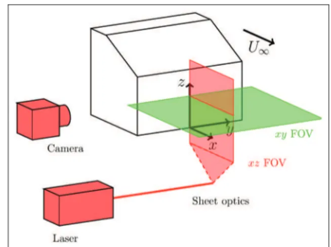
The flow was seeded with Vestosint spherical parti-cles (Vestosint, Germany) with a density of 1.016 g/cm3 and a mean size of 56 mm. A 5 W continuous laser (CNI, China) was used to illuminate these particles behind the vertical back of the Ahmed model. The laser emitted light with a wavelength of 532 nm, passing through a planar-convex lens to spread the beam into a 2 mm thick laser sheet. Seventeen equi-spaced vertical (xz) planes from y=W = ÿ 0:103 to y=W = 0:720 ðDy = 5 mmÞ and 12 equi-spaced spanwise (xy) planes from z=H = 0 to z=H = 1:108 ðDz = 5 mmÞ were acquired using a PCO Dimax S4 (PCO, Germany) camera (resolution 201632016 pixels) with a Nikkor 105 mm lens. Since a continuous wave laser was used for illumination, the exposure control of the camera was used to control the light level of each recorded image. Figure 2 shows the location of the PIV planes relative to the body. The PIV parameters used at each Figure 1. Structures in the wake of the Ahmed body.1The
labels A and B are used throughout the text to refer to the vortices so labelled in this schematic.
Figure 2. Schematic of the experimental setup. The camera and laser positions are correct only for the xz acquisition planes (FOV), as shown in red. For the xy planes (in green), the camera is placed below the channel and the laser is positioned where the camera is in this schematic. The origin of the coordinate planes is at the base of the rear surface of the model, in the symmetry plane. Only a single xz and xy plane are included for clarity.
Table 1. PIV parameters for the two different measurement planes. xz xy Number of pairs 1500 1500 Dt 2 ms 2 ms Frame rate 10 Hz 10 Hz Magnification 29.5 px/mm 17.7 px/mm Field of view 0:26L30:94H 0:44L31:17W Vectors 2493249 2493249
acquisition plane are given in Table 1. The image pairs were analyzed using in-house cross-correlation software with a window size of 32332 pixels and an overlap of 75% to estimate the two components of velocity in the image plane. The software was originally described in the work by Fouras et al. for the more complicated case of target-free stereo PIV,16although only the itera-tive multi-window processing technique for a single camera is required here. It has been subsequently fur-ther developed and updated since.14,17,18
Results
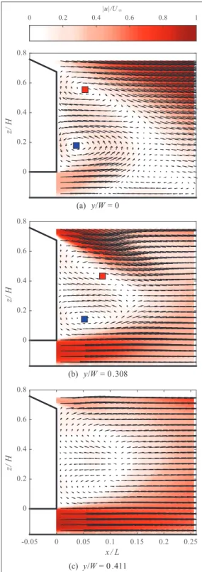
Figure 3(a) shows the velocity field in the body’s sym-metry plane. The recirculation regions A and B are evi-dent as a pair of counter-rotating vortices behind the base of the model. The G1 criterion is used to highlight regions of local rotation throughout the flow.19 As is evident in Figure 3, the maximum and minimum of G1 correspond to the cores of the A and B vortical struc-tures respectively. If a plane further towards the edge of the body is considered, Figure 3(b) and (c), the regions become much less defined. Once the plane at y=W = 0:411 is reached, the G1 criteria no longer detects the cores of these regions.
Due to the high spatial density of the xz PIV planes the cores of the vortices can be tracked across the span (Figure 4). For y=W \ 0:2, the streamwise location of both the A and B cores increases slightly, indicating a bend in the core. After y=W = 0:2, the streamwise posi-tion suddenly increases, especially of the A region, due to the bending of the region by the streamwise flow coming around the sides of the body. No data can be presented for planes beyond y=W = 0:4 because the region is so ill-defined that its core location cannot be determined, that is, there is no core hence no core can be located (Figure 3(c)).
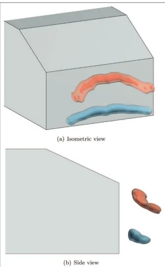
Figure 5 shows the isosurfaces of spanwise G1, giving the spatial evolution of the recirculation regions across the span. Close to the edge of the body, the A region tilts more into the streamwise direction than it does downwards. This is as expected if the regions were horseshoe vortices as opposed to a vortex torus or ring. The circulation bound in each of these regions was extracted through integration of the velocity field. Figure 6 shows how the circulation varies with spanwise position. The circulation in region B linearly decreases in magnitude with spanwise position, but region A has a more abrupt decrease. As the circulation is varying, and since circulation cannot be created except at the boundary of the body, some of the circulation must be tilted into another direction. This could be either the streamwise, supporting the twin-horseshoe interpreta-tion, or the vertical direcinterpreta-tion, suggesting the vortex takes a toroidal shape.
If these structures were joined in a torus shape, one would expect to see rotating flow due to these struc-tures in horizontal planes taken at a range of heights
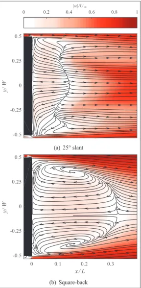
along the back surface. Figure 7 shows such a plane; clearly there is no rotation in the expected regions of the torus. For comparison, a PIV slice through the mid-height of a square-back Ahmed body is shown in Figure 7(b), demonstrating the vertical vortices that are present within a toroidal wake. The contrast shown Figure 3. Flow in the xz planes behind the Ahmed model with velocity vectors overlaid onto contours of total velocity magnitude. Only one in one hundred velocity vectors are shown for clarity. The red and blue points indicate the core of the A and B vortical structures respectively, found as the maximum and minimum of G1respectively.
here is quite stark, but the only difference between the two experiments is the rear slant angle changing to 0°. If the vortices were horseshoes as proposed, the trailing legs of these would be seen in a plane orthogonal to the main flow. Such an experiment was performed where the laser plane for the PIV was parallel to the rear sur-face of the body.20This has been reproduced in Figure 8. Here the B vortex is seen at the base of the model. The upper vortex contains both the A and C-pillar vor-tices.14On the negative y side, the A vortex can be seen separately and below the C-pillar vortex, before they fully merge.
The velocity data from the two different orientations was reconstructed into a three-dimensional velocity field, comprising all three velocity components in a volume located behind the base. Three-dimensional streamribbons are presented in Figure 9. These were generated by seed points in and around the A and B vortical structures. Particularly for the lower (B) region, a very cohesive picture is shown of flow rolling up into the core of the vortex and being transported to the sides of the body. Notice that all of the blue streamribbons, which are seeded uniformly across the span, ultimately move downstream only at the edges of the body. This demonstrates that there is a sufficient spanwise flow to move all of the fluid at the centre of the body that is within the B vortex to the edges of the body. As the flow reaches the edge of the body, the shear of the
essentially free-stream velocity in the streamwise direc-tion causes the streamribbons to tilt into that direcdirec-tion. This is further support for the theory that the A and B vortices are in fact two horseshoe shaped vortices situ-ated above each other.
When the same procedure is followed for region A, the flow pattern is less coherent. The recirculatory nature of the flow is still evident, but the vortex is not as coherent as B, neither is the spanwise flow as strong. This is understandable as the B region is produced by a high shear region of near free-stream velocity reaching the low pressure region and rolling around the bottom edge. For the A region, the flow is first separated at the top of the slant, and reattaches (in the mean flow sense) at the end of the slant, shortly before it separates again and forms the A region.
Since the A vortex is tilted in the streamwise direc-tion, the vortex core is now parallel with, and close to, the C-pillar vortex. It is hypothesised that these struc-tures would merge. This hypothesis has been presented before by using the sudden increase of circulation in the pillar vortex to suggest the merging of the A and C-Figure 5. Three-dimensional representations of spanwise G1
criterion. Red represents a positive rotation (A region), blue represents a negative rotation (B region). Colours are consistent with Figure 4.
Figure 4. Core location of the A (red, squares) and B (blue, circles) vortical structures against spanwise position.
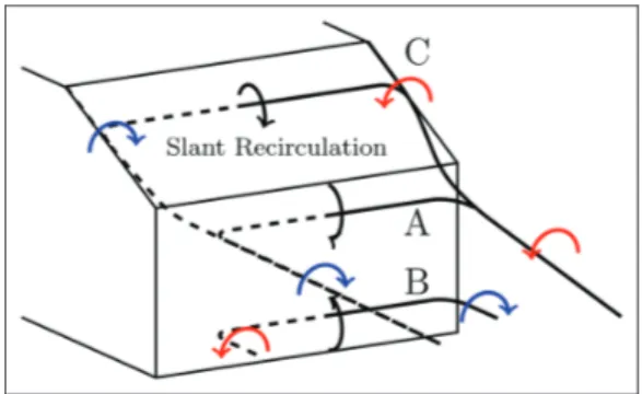
pillar structures.14 The data in this present paper sup-ports this view. The suggested wake structure is sche-matised in Figure 10, where the cores of each of the regions are indicated by solid lines.
Figure 7. (a) Flow in the xy plane at z=H = 0:369 with velocity streamlines overlaid onto filled contours of total velocity. (b) Flow behind the square-back Ahmed geometry at the mid-height plane clearly showing the vertical legs of the toroidal vortex. Streamlines are used to indicate the local flow direction only.
Figure 9. Streamribbons with seed points in the A (red) and B (blue) regions. Especially in the B region, spanwise flow is clearly evident until the edge of the body, where the streamribbons are tilted in the streamwise direction.
Figure 8. Cross-stream PIV plane 0.1L behind the high-drag Ahmed model showing the trailing legs of the B vortex as well as the combined A and C-pillar vortices. One in 64 vectors are displayed for clarity. Filled contours are G2ranging from 21 in
blue (clockwise rotation) to 1 in red (counter-clockwise rotation). Source: reproduced with permission from Monash University, 2016.20
Figure 6. The spanwise circulation bound in the A (red, squares) and B (blue, circles) vortical structures against spanwise position. Circulation is non-dimensionalised with the free-stream velocity and the square-root of the frontal area.
Conclusions
This paper presents a strong case to support the hypoth-esis that the time-mean near-wake behind the vertical sur-face of the Ahmed body at moderate Reynolds numbers is comprised of two horseshoe vortices, as opposed to the toroidal shape some suggest. This is shown through high spatial-resolution velocity fields taken in orthogonal planes close to the body showing the roll-up of the vorti-cal structures along both horizontal edges of the Ahmed base, but no such formation on the vertical edges.
The circulation along the span was quantified and shown to be decreasing near the side edges of the body. Due to Kelvin’s theorem, this indicates the tilting of cir-culation into another plane. The three-dimensional representations of the data show that this other plane is the streamwise direction rather than the vertical direc-tion, showing this structure to not be toroidal. This data provides further support for the hypothesis that the cir-culation from the A-region in fact feeds into and strengthens the C-pillar trailing vortices.14
Acknowledgement
The authors would like to thank Mr J Meikle for the assistance in data acquisition for this paper.
Declaration of conflicting interests
The author(s) declared no potential conflicts of interest with respect to the research, authorship, and/or publi-cation of this article.
Funding
The author(s) disclosed receipt of the following finan-cial support for the research, authorship, and/or publi-cation of this article: This work was supported by the Australian Research Council (ARC) through the Linkage Project (grant number LP0991170) and the Centre National de la Recherche Scientifique (CNRS) under the Projet International de Cooperation Scientifique (grant number PICS161793).
References
1. Ahmed SR, Ramm G and Faitin G. Some salient features of the time-averaged ground vehicle wake. Report, Society of Automotive Engineers, Inc., Warrendale, USA, 1984. 2. Kourta A and Leclerc C. Characterization of synthetic
jet actuation with application to Ahmed body wake. Sens Actuators A Phys2013; 192: 13–26.
3. Beaudoin JF and Aider JL. Drag and lift reduction of a 3D bluff body using flaps. Exp Fluids 2008; 44(4): 491–501. 4. Beaudoin JF, Cadot O, Aider JL, et al. Cavitation as a
complementary tool for automotive aerodynamics. Exp Fluids2004; 37(5): 763–768.
5. Joseph P, Amandole`se X and Aider JL. Drag reduction on the 25° slant angle Ahmed reference body using pulsed jets. Exp Fluids 2012; 52(5): 1–17.
6. Drouin V, Giovannini A and Gillie´ron P. Topology and characterisation of the vortical near-wake flow over a simplified car model. In: Conference on bluff body wakes and vortex-induced vibrations (BBVIV3), Port Douglas, Australia, December 2002, pp.1–4.
7. Wang XW, Zhou Y, Pin YF, et al. Turbulent near wake of an Ahmed vehicle model. Exp Fluids 2013; 54(4): 1490. 8. Zhang BF, Zhou Y and To S. Unsteady flow structures around a high-drag Ahmed body. J Fluid Mech 2015; 777: 291–326.
9. Roume´as M, Gillie´ron P and Kourta A. Analysis and control of the near-wake flow over a square-back geome-try. Comput Fluids 2009; 38(1): 60–70.
10. Grandemange M, Gohlke M and Cadot O. Turbulent wake past a three-dimensional blunt body. Part 1. Global modes and bi-stability. J Fluid Mech 2013; 722: 51–84. 11. Evrard A, Cadot O, Herbert V, et al. Fluid force and
symmetry breaking modes of a 3D bluff body with a base cavity. J Fluids Struct 2016; 61: 99–114.
12. Perry AK, Pavia G and Passmore M. Influence of short rear end tapers on the wake of a simplified square-back vehicle: Wake topology and rear drag. Exp Fluids 2016; 57(11): 169.
13. Franck G and D’Elı´a J CFD modeling of the flow around the Ahmed vehicle model. In: Proceedings of 2nd
confer-ence on advances and applications of GiD Barcelona,
Spain, February 2004, pp.1–4.
14. Venning J, Lo Jacono D, Burton D, et al. The effect of aspect ratio on the wake of the Ahmed body. Exp Fluids 2015; 56(6): 126.
15. Krajnovic´ S and Davidson L. Flow around a simplified car, part 2: Understanding the flow. J Fluids Eng 2005; 127(5): 919.
16. Fouras A, Lo Jacono D and Hourigan K. Target-free stereo PIV: A novel technique with inherent error estimation and improved accuracy. Exp Fluids 2007; 44(2): 317–329. 17. Sherry M, Nemes A, Lo Jacono D, et al. The interaction
of helical tip and root vortices in a wind turbine wake. Phys Fluids2013; 25(11): 117102.
18. Nemes A, Lo Jacono D, Blackburn HM, et al. Mutual inductance of two helical vortices. J Fluid Mech 2015; 774: 298–310.
19. Graftieaux L. Combining PIV, POD and vortex identifi-cation algorithms for the study of unsteady turbulent swirling flows. Meas Sci Technol 2001; 12(9): 1422–1429. 20. Venning J. Vortex structures in the wakes of two- and
three-dimensional bodies. PhD Thesis, Monash Univer-sity, Australia, 2016.
Figure 10. Vortex structure schematic in the wake of the Ahmed body, with lines indicating the location of the vortex cores. The structure is dashed for y=W \ 0 and solid for
y=W . 0. Spanwise rotation is indicated by black arrows and streamwise rotation is indicated by red or blue arrows for positive or negative rotation, respectively.